
Related Manuals for REMKO HTL 200-EC


Summarization of Contents
Safety Notes and Precautions
General Safety Guidelines
Essential safety rules for unit operation, covering general precautions and specific warnings for safe use.
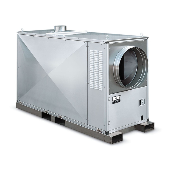
Unit Description and Installation Instructions
Unit Features, Operation, and Locations
Details unit design, operating sequence, suitable locations, and application areas for commercial use.
Installation Requirements and Air Supply
Key requirements for installation, focusing on adequate air supply, exhaust routing, and location criteria.
Unit Installation Procedures
Installation Location and Safety Distances
Guidelines for selecting an installation location and maintaining required safety distances around the unit.
Installation Guidelines and Considerations
Covers stable mounting, accessibility, hazard prevention, and spatial requirements for installation.
Exhaust, Fuel, and Electrical Systems
Exhaust Gas Ducting and Outdoor Operation
Procedures for exhaust gas ducting and guidelines for operating the unit outdoors safely.
Fuel Supply and Electrical Connection
Details on ensuring adequate fuel supply and the required electrical connection specifications.
Warm Air Distribution and Operation Modes
Warm Air Hose Usage
Specific instructions for using warm air hoses, covering selection, installation, and preventing kinks.
Modes of Operation: Fresh Air and Recirculation
Explains the unit's fresh air and air recirculation modes, including required accessories.
Safety Equipment and Controls
Triple-Function Controller and Safety Devices
Details the triple-function controller, safety devices like TR, TW, STB, and their functions.
Regulating Devices and Probe Handling
Explains regulating devices, self-monitoring sensors, and correct probe installation and maintenance.
Commissioning and Operation
Starting the Unit and Control Panel Overview
Step-by-step guide to starting the unit and an overview of the control panel functions.
Unit Operation Modes and Cycling
Describes automatic operation, burner cycling, and potential interruptions during heating.
Fan Operation, Shutdown, and Maintenance
Fan Mode Operation and Shutdown Procedures
Details fan-only mode operation and the correct shutdown sequence for the unit.
General Care, Maintenance, and Checks
Instructions for general cleaning, maintenance tasks, component checks, and adherence to schedules.
Cleaning Tasks and Component Handling
Removing the Combustion Chamber
Detailed procedure for removing the combustion chamber and heat exchanger for cleaning.
Cleaning Components and Reassembly
Steps for cleaning heat exchanger components and reassembling the unit after disassembly.
Forced-Air Oil Burner Commissioning
Preparatory Tasks and Nozzle Adjustments
Essential preparatory steps for burner commissioning, including nozzle and air inlet adjustments.
Baseplate Refitting and Regulatory Compliance
Guidance on refitting the baseplate and adhering to relevant environmental regulations.
Secondary Air and Pump Pressure Calibration
Adjusting Secondary Air (Nozzle Fitting)
Procedure for presetting and adjusting the secondary air via the nozzle fitting.
Setting the Pump Pressure
Detailed steps for adjusting and checking the pump pressure during commissioning and service.
Actuator Functionality and Settings
Actuator: Air Exclusion and Stage 1 Volume Control
Explains the actuator's role in air exclusion and controlling air volume for stage 1.
Actuator: Stage 2 Operation and Solenoid Valve Control
Details the actuator's function for stage 2, including solenoid valve control and air volume adjustments.
Air Flap and Air Volume Adjustment Procedures
Adjusting Air Flap and Stage 1 Air Volume
Instructions for adjusting the air flap and fine-tuning air volume for stage 1 operation.
Setting Solenoid Valve 2 and Stage 2 Air Volume
Steps for setting the solenoid valve 2 switching point and adjusting air volume for stage 2.
Troubleshooting Common Issues
Unit Startup Failures
Troubleshooting steps for unit startup failures, covering power, thermostat, and safety limiter issues.
Burner, Fan, and Power Supply Faults
Diagnosing issues with the forced-air burner, power supply, and supply air fan operation.
Intended Use, Support, and Disposal
Intended Use and Operational Limitations
Defines the unit's intended applications and specifies limitations and operator responsibilities.
Customer Service, Guarantee, and Recycling
Information on customer service, guarantee claims, and environmentally friendly disposal of packaging and old units.
Exploded View of the Unit
Component Identification Diagram
Diagram illustrating the exploded view of the unit with numbered components for identification.
Spare Parts Identification
Spare Parts List with EDP Numbers
A comprehensive list of spare parts with their corresponding EDP numbers for both HTL 200-EC and HTL 250-EC models.
Electrical Wiring Diagrams
EC-Fan Wiring Diagram and Legend
Detailed electrical wiring diagram for the EC-fan, including a legend for components and connections.
Maintenance Protocol and Log
Maintenance Checklist and Recording Form
A protocol form for recording maintenance tasks, checks, and test runs with date and signature fields.
Technical Data and Specifications
Unit Specifications and Performance Metrics
Comprehensive technical data for HTL 200-EC and HTL 250-EC, including heating capacity, flow rates, and power consumption.
Need help?
Do you have a question about the HTL 200-EC and is the answer not in the manual?
Questions and answers