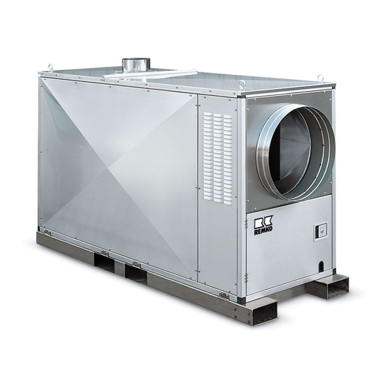
Summarization of Contents
Before Starting
Installation requirements
Essential steps for proper unit placement and setup.
Power supply
Guidelines for connecting the unit to the electrical mains.
Hot air distribution
Information on directing the heated air output effectively.
Starting
Starting of device
Procedure for initiating the unit's operation.
Heating operation
Steps for running the unit in heating mode.
Shut Down
Attention, after-cooling phase!
Critical note on the post-shutdown cooling cycle.
Troubleshooting Instructions
Unit does not start
Steps to diagnose and resolve startup issues.
Burner does not start
Guidance for troubleshooting burner ignition problems.
Fan does not start
Steps to identify and fix fan related startup failures.
Maintenance
Cut unit from the mains!
Crucial safety step before performing any service.
Removal of combustion-chamber
Detailed steps for disassembling the combustion chamber.
Service
Heat exchanger cleaning
Procedure for cleaning the heat exchanger components.
Combustion chamber cleaning
Steps for cleaning the internal combustion chamber.
Burner maintenance
Guidelines for professional burner upkeep and checks.
Assembly of combustion chamber
Instructions for reassembling the combustion chamber.
Exploded View
Unit design
Diagram illustrating the overall unit components.
Combustion chamber & heat-exchanger
Specific diagram of combustion chamber and heat exchanger parts.
Oil Burner
Air inlet device
Adjustment of air intake for optimal burner performance.
Secondary air setting
Adjusting secondary air for efficient combustion.
Setting the pump pressure
Procedure for setting and checking oil pump pressure.
Servomotor LKS 130-2
Setting the air throttle
Adjusting air throttle for optimal combustion.
Setting air volume stage 1
Regulating air volume for the first operating stage.
Switch point solenoid valve 2
Setting the switch point for the solenoid valve stage 2.
Setting air volume stage 2
Adjusting air volume for the second operating stage.


Need help?
Do you have a question about the HTL 250-FB and is the answer not in the manual?
Questions and answers