
Related Manuals for REMKO HTL 250 FB


Summary of Contents for REMKO HTL 250 FB
-
Page 1: Spare Parts
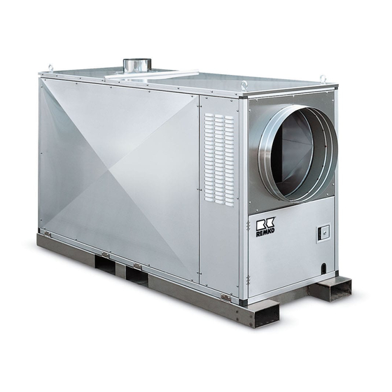
REMKO HTL 150 FB - HTL 250 FB Mobile oil-fired heating centers Operation Technology Spare Parts Edition D – R02 REMKO – powerful like a bear. -
Page 3: Table Of Contents
Safety Instructions Forced-Air Oil Burner Description of Device Safety Mechanisms Exploded View Spare Part List Unit Assembly Wiring Diagram HTL 150 FB Prior to Operation Initial Operation Wiring Diagram HTL 200/250 FB Shutting Down the Unit Wiring Diagram HTL-FB Technical Data... -
Page 4: Safety Instructions
Safety Instructions Description of Device Make sure to observe relevant local building and fire The units are fired directly with heating oil or diesel. protection codes and abide by professional associa- They are designed for fully-automatic, universal and tion regulations when the unit is in operation reliable use. -
Page 5: Safety Mechanisms
If the three-speed combination regulator needs to be re- Before releasing the safety temperature limiter (STB), the possible causes of the malfunction placed, only use the original REMKO-spare part ref. no. must be identified. 1102562. The fan motor is monitored by a thermal overcurrent re- Make sure to observe the following: lay. -
Page 6: Unit Assembly
Unit Assembly ◊ A natural air supply sufficient for combustion exists When setting up the units, the relevant regional building and fire protection codes of the respective region must when, for example, be observed. - the room content in m³ is equivalent to at least 10 times the rated heat output in kW of all heating When selecting an indoor or outdoor location to set up units in operation in the room and natural air venti-... - Page 7 Operating modes Electrical connection ◊ The units are operated with 400/3~N/50. The units can be used in the fresh air and circulation modes. ◊ The unit must be connected to the power source at a special terminal equipped with a switch to protect against faulty currents in accordance with VDE 0100 Fresh air mode §...
-
Page 8: Prior To Operation
Prior to Operation Initial Operation Prior to initial operation, check the unit for any visual A person who has been adequately trained in how to defects on the control and safety mechanisms, make operate the unit is to be given responsibility for operat- sure that it has been installed correctly and that it has ing and monitoring it. -
Page 9: Shutting Down The Unit
Circulation mode The burner doesn’t start In this operating mode, only the air supply fan runs and 1. Open the shut-off valve on the oil filter. the unit can be used to circulate air. 2. Check the oil filter for dirt. Thermostat regulation and heating operation are not 3. -
Page 10: Maintenance And Service
Maintenance and Service Cleaning The complete unit including heat-exchanger, combus- Regular maintenance and observance of some basic tion chamber and forced-air oil burner must be cleaned principles are required to ensure a long service life and for dust and dirt after every heating period or before if to keep the unit functioning properly. -
Page 11: Customer Service And Guarantee
1. Put together the disassembled parts in the opposite pletely fill out the “guarantee certificate” enclosed with all heating units and send it back to REMKO GmbH & order Co. KG in a timely manner after purchasing the unit and 2. -
Page 12: Forced-Air Oil Burner
Forced-Air Oil Burner Adjusting the air intake nozzle The necessary burner pressure can be adjusted with- After loosening the 4 housing screws and the additional out changing the outlet diameter using the adjustable 2 screws (pay attention to the arrow), the assembly air intake nozzle depending on the combustion cham- base plate is removed from the housing and suspended ber resistance and chimney draft. - Page 13 Adjustment motor function Setting “Air quantity level 1” (adjustment lever blue) The adjustment motor has three set positions as well as an activation contact for the “Magnetic valve level 2”. Unplug the 4-pin multi-purpose connection. Thermostat level 2. Turn the orange adjustment lever “Air quantity Level 2” and the black adjustment lever “Magnetic valve 2”...
-
Page 14: Exploded View
Exploded View Unit housing Combustion chamber with heat-exchanger We reserve the right to make changes to dimensions and design in the interest of technical progress. -
Page 15: Spare Part List
Spare Part List HTL 150 FB HTL 200 FB HTL 250 FB Description Ref. No. Ref. No. Ref. No. Cover plate, rear 1105335 1105335 1105335 Rosette for exhaust gas connection 1103023 1103023 1103023 Connecting profile 1105312 1105312 1105312 Cover plate, front... -
Page 16: Wiring Diagram Htl 150 Fb
Wiring Diagram HTL 150 FB triple combination control Dreifach-Kombinationsregler X1:4 X1:5 X1:8 X1:7 X1:6 X1 4 1 = heating 1=Heizen 2 = ventilate 2=Lüften X1 5 X1 6 X1 7 X1 11 X1 12 X1 8 X3 4 X3 5... -
Page 17: Wiring Diagram Htl 200/250 Fb
Wiring Diagram HTL 200/250 FB triple combination control Dreifach-Kombinationsregler X1:4 X1:5 X1:8 X1:7 X1:6 X1 4 1 = heating 1=Heizen 2 = ventilate 2=Lüften X1 5 X1 6 X1 7 X1 11 X1 12 X1 8 X3 4 X3 5 X3 1 Brennerstecker (WS) burner plug (WS) -
Page 18: Wiring Diagram Htl-Fb
(free) TW = Temperature monitor WS = Wieland plug to the burner X3 = Terminal box front Technical Data Model HTL 150 FB HTL 200 FB HTL 250 FB Rated heat power max, Rated heat output Rated air output m³/h... -
Page 19: Maintenance Log
Maintenance Log Model: : ........ Model No.: : ........Burner : ........ Burner No.: : ........9 10 11 12 13 14 15 16 17 18 19 20 Clean unit -surface- Clean unit -interior- Clean fan Clean combustion chamber Clean heat exchanger Clean/replace exhaust gas suppressor Replace seals -inspection cover- Replace seals –burner-... - Page 20 REMKO GmbH & Co. KG Klima- und Wärmetechnik D-32791 Lage Im Seelenkamp 12 • D-32777 Lage PO Box 1827 • Phone +49 (5232) 606 - 0 +49 (5232) 606260 E-Mail: info@remko.de Internet: www.remko.de...
Need help?
Do you have a question about the HTL 250 FB and is the answer not in the manual?
Questions and answers