
Related Manuals for Rottler S7A


Summarization of Contents
ORDERING PROCEDURE
Contacting Rottler for Parts
How to contact Rottler for ordering optional equipment, replacement parts, or tooling.
Information Needed for Ordering
Details required to expedite the ordering process for parts and tooling.
Minimum Order Requirement
Specifies the minimum order amount for parts.
INTRODUCTION
Safety Before Operation
Emphasizes reading safety chapters and understanding all safety issues before operating.
Validating Warranty
Instructions for owners to validate their Rottler machine warranty.
Understanding Machine Operation
Suggests reading control definitions and operating instructions for better understanding.
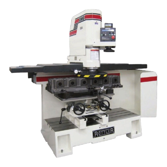
Machine Description
Describes the S7A & S8A surfacing machine and its design purposes.
Disclaimer
Legal disclaimer regarding the manual's content and use.
Limited Warranty
Details the limited warranty for Rottler S7A & S8A parts and equipment.
Warranty Exclusions and Limitations
Lists conditions under which the warranty does not apply.
Merchandise Return Policy
Outlines the procedure and conditions for returning merchandise.
INSTALLATION
S7/S8 Installation Report
Refers to the installation report needed for warranty qualification.
Installation Procedure Overview
Lists various steps involved in the machine installation procedure.
Owner/Business Manager Notification
Instructs owners to sign the installation report to validate the warranty.
Electrical Power Requirements
Specifies voltage, phase, and current requirements for the machine.
Grounding Connection Description
Requires brief description of the isolated ground connection.
Machine Start-Up Procedures
Steps to follow before turning power on and initial start-up.
Operator Training Guidelines
Key areas to cover during operator training for the machine.
Machine Maintenance Overview
Lists key maintenance areas for the machine.
Cylinder Head Resurfacing Setup
Steps for setting up the machine for cylinder head resurfacing.
V6/8 Block Resurfacing Setup
Instructions for setting up for V6/8 block resurfacing.
In-Line Block Resurfacing Setup
Procedures for setting up in-line block resurfacing.
General Remarks and Further Steps
Notes on machine performance, adjustments, and required items for installation completion.
Sending Completed Installation Form
Instructions on where to send the completed installation form.
Location Considerations
Importance of proper location and material handling for productivity.
Unpacking Instructions
Guidance on carefully removing the machine from its crate.
Shipping Hold Down Bolt Removal
Steps to remove the shipping hold down bolt from the spindle base.
Leveling Procedure
Instructions on how to level the machine using set screws and a precision level.
Air Supply Requirements
Importance of dry air supply and connection details.
Power Supply Specifications
Details power requirements, voltage, phase, and frequency.
Grounding Procedure
Instructions for connecting the machine to a proper earth ground.
SAFETY
Safety Information Overview
General safety advice and warning symbol explanations.
Safety Instructions for Machine Use
Rules for safe operation of the machine.
Hazard Alert Symbols and Meanings
Explains DANGER, WARNING, and CAUTION symbols and their implications.
Operator Qualifications and Guards
Emphasizes qualified operators and keeping guards in place.
Workplace Safety Practices
Guidelines for a clean work area, apparel, and avoiding over-reaching.
Safety Glasses and Accessories
Importance of safety glasses and using recommended accessories.
Damaged Parts and Condition Checks
Procedure for checking and replacing damaged parts.
Operating Under Influence and Modifications
Warnings against operating while impaired and unauthorized modifications.
Flying Metal Chips and Protective Clothing
Safety measures for flying metal chips and protective clothing.
Electrical Power Safety
Dangers associated with electrical power and grounding requirements.
Electrical System Compliance
Emphasizes local code compliance and potential upgrades for electrical systems.
Machine Control and Emergency Stop
Machine's computerized control susceptibility and emergency stop location.
Machine Operator Qualifications
Requirements for a skilled machinist operator.
Cutting Tool Area Safety
Safety precautions for the cutting tool area and hand placement.
Machining Safety Precautions
Eye protection, chip guards, and keeping hands clear during machining.
Work Loading and Maintenance Safety
Safe handling for loading/unloading and power disconnection for maintenance.
Emergency Procedure
Steps to take in case of an emergency, including using the E-Stop.
CONTROL DEFINITIONS
Control Definitions Overview
Introduces the chapter's purpose of defining control functions.
Key Control Components
Lists and page references for CPU control, power switch, and buttons.
Control Panel Button Layout
Illustrates the front control panel and labels various buttons.
Emergency Stop and Homing Procedures
Explains emergency stop function and machine homing process.
Travel and Spindle Control Buttons
Details functions of travel, spindle start, and related buttons.
Spindle Height Adjustment Controls
Explains Relief Up, Up/Dn Adjust, and Mill buttons for spindle height.
Touch Off and Cut Length Settings
Covers setting touch off points and mill cut length.
Feed, Speed, and Cycle Control
Details feed rate, spindle RPM, and cycle start functions.
Surface Depth Indicator
Location and purpose of the surface depth dial indicator.
Machine Parameters Access and List
How to access and a list of machine parameters.
Spindle Auto Set-Up Procedure
Steps for performing the Spindle Auto Set-Up.
Horizontal Auto Set-Up Procedure
Steps for performing the Horizontal Auto Set-Up.
Manual Power Up
How to manually power up the drives.
OPERATING INSTRUCTIONS
Operating Instructions Overview
General guide to using the machine for surfacing.
Cutting Inserts Overview
Lists available cutting inserts with page references.
Machine Cutting System Usage
Describes different ways to use the S7A and S8A cutting system.
Manual Operation Procedure
Step-by-step guide for manual operation of the machine.
Automatic Operation Procedure
Step-by-step guide for automatic operation of the machine.
Cutting Inserts Descriptions
Detailed descriptions of various Rottler cutting inserts.
Cutting Insert Model Details
Further details on specific cutting insert models.
One Insert vs. Two Inserts
Comparison and guidelines for using one or two inserts.
General Information on Inserts
Information on insert designations and toolholders.
Cutting Speed Calculation Formula
Formula and table for calculating cutting speeds and RPM.
MAINTENANCE
Maintenance Overview
Lists various maintenance topics covered in the section.
Lubrication Schedule
Details lubrication points and frequencies.
Machine Lubrication Illustrations
Refers to illustrations for machine lubrication.
Setting Cutting Tool Inserts
Procedure for setting cutting tool inserts.
Spindle and Ball Screw Adjustments
Covers spindle sensor, ball screw, cutterhead tilt, and spindle adjustments.
Air System Adjustment
Details on adjusting the counter balance air cylinder regulator.
Bearing and Washer Alignment
Definitions for bearing and Belleville washer alignment.
Lubrication Details
Specific lubrication points and frequencies for components.
Cleaning Way Surface
Instructions on cleaning the sliding way surfaces.
Lubrication Quick Reference Chart
A chart summarizing lubrication points and frequencies.
S7A-8A Machine Lubrication Illustration
Diagram showing lubrication points on the machine.
2 Axis Universal Machine Table Lubrication
Illustration showing lubrication points for the machine table.
Production Cutting Setup
Instructions for setting up for production cutting of aluminum and cast iron.
Dial Indicator Setting Procedure
Steps for setting the dial indicator for precise measurements.
Vertical Travel Belt Removal and Replacement
Procedure for removing, replacing, and adjusting the vertical travel belt.
Upper Vertical Travel Belt Adjustment
Details for replacing and adjusting the upper vertical travel belt.
Drive Belt Replacement Procedure
Step-by-step guide for drive belt replacement.
Drive Sprocket / Motor Removal
Instructions for removing the drive sprocket and motor.
Drive Sprocket Replacement
Steps for replacing the drive sprocket.
Driven Sprocket Removal
Instructions for removing the driven sprocket.
Driven Sprocket Replacement
Steps for replacing the driven sprocket.
Cutterhead and Chip Guard Removal
Procedure for removing the cutterhead and chip guard.
Upper Housing Removal Procedure
Steps for removing the upper housing.
Inner Spindle Removal Steps
Detailed steps for removing the inner spindle.
Upper Spindle Bearing Removal
How to remove the upper spindle bearing.
Spindle Sensor Adjustment
Procedure for adjusting the spindle sensor.
Horizontal Ball Screw and Belt Alignment
Detailed steps for aligning the horizontal ball screw and adjusting belt tension.
Air Adjustment of the S7A-8A Machine
Details on adjusting the counter balance air cylinder regulator.
Pneumatic Control Diagram
Diagram illustrating the pneumatic control system.
Cutterhead Tilt Adjustment Procedure
Steps for adjusting the cutterhead tilt with a dial indicator.
Outer Spindle Bearing Adjustment
Procedure for adjusting the outer spindle bearings.
Inner Spindle Adjustment Procedure
Steps for adjusting the inner spindle.
Bearing Alignment Definitions
Visual definitions for bearing alignment.
Belleville Washer Alignment Definitions
Visual definitions for Belleville washer alignment.
Z-Axis Vertical Ballscrew Lower Bearing Stacking
Order for installing Z-axis vertical ballscrew lower bearings.
Inner Spindle Upper Belleville Washer Stacking
Order for installing inner spindle upper Belleville washers.
Inner Spindle Lower Bearing Stacking
Order for installing inner spindle lower bearings.
TROUBLESHOOTING
Contacting Rottler for Service
Information on how to contact Rottler for service assistance.
MACHINE PARTS
Parts Section Overview
Lists various machine parts sections.
Component Diagrams and Details
Diagrams and parts lists for pneumatic, electrical, and housing components.
Front / Right Side View and Dimensions
Shows front/right side views with key dimensions.
Pneumatic Assembly Details
Detailed diagram of the pneumatic assembly with part labels.
Electrical Wiring Diagram Details
Detailed view of the electrical wiring diagram.
Electrical Enclosure Parts List
Detailed parts list for the electrical enclosure.
Upper Housing Parts List
Detailed parts list for the upper housing.
Upper Vertical Travel Belt Parts
Diagram and labels for upper vertical travel belt parts.
Spindle Base Front Section Parts
Diagram and parts list for the spindle base front section.
Inner / Outer Spindle Assembly Parts
Diagram and parts list for the inner/outer spindle assembly.
Spindle Base Bushings Diagram
Diagram showing spindle base bushings and related parts.
Spindle Base Assembly Diagram
Exploded view of the spindle base assembly.
Left Ballscrew Support Diagram
Exploded view of the left ballscrew support assembly.
Right Ballscrew Support Diagram
Exploded view of the right ballscrew support assembly.
Home and Limit Switches Diagram
Diagram showing home and limit switch components.
Pendant Assembly Diagram
Exploded view of the pendant assembly.
Spindle Base Cover Diagram
Diagram showing the spindle base cover.
Chip Shield Diagram
Diagram of the chip shield assembly.
14" Fly Cutter Assembly
Exploded view of the 14" fly cutter assembly.
Chip Chute Diagram
Diagram showing the chip chute.
Waycovers and Chip Catcher Assembly
Diagram of waycovers and optional chip catcher.
Riser Set Diagram
Diagram showing the riser set.
OPTIONS
Optional Equipment Information
Notes that optional equipment catalog is on the manual CD.
MSDS
NAPA Lithe-Ease Grease
Introduces NAPA Lithe-Ease Grease MSDS.
Material Safety Data Sheet - Product Identification
Provides product identification details for NAPA Lith-Ease Grease.
Hazardous Ingredients
Lists hazardous ingredients for the grease.
MSDS Physical and Fire Data
Details physical properties and fire data of the grease.
Health and First Aid Information
Covers reactivity, first aid, and health effects of the grease.
Ventilation and Protective Measures
Recommended ventilation and personal protective equipment.
Storage and Handling Procedures
Guidelines for storing and handling the grease.
Spill Procedures and Waste Disposal
Procedures for handling spills and disposing of waste.
Need help?
Do you have a question about the S7A and is the answer not in the manual?
Questions and answers