
Related Manuals for Metronix smartServo BL 4104-C


Summarization of Contents
1 About this Product manual
1.1 Explanations and notation
Explains notation and structure of warning notes within the manual.
1.2 Additional documents
Lists other relevant manuals and resources for the product.
1.3 Order numbers
Provides product order numbers for identification and purchasing.
1.4 Applicable standards
Lists relevant industry standards the product complies with.
2 For your own safety
2.1 General information
Provides general safety guidelines for using the servo drive.
2.2 Intended use
Defines the proper application and limitations of the servo drive.
2.3 Target group
Identifies the qualified personnel authorized to work with the drive.
2.4 General safety instructions
Outlines essential safety rules and regulations for operation.
2.5 Personal protective equipment
Lists necessary PPE for safe handling and maintenance.
2.6 Safety notes for installation and maintenance
Covers safety precautions during installation and maintenance.
2.7 Protection against contact with electrical parts
Details measures to prevent electrical shock hazards.
2.8 Protection against electric shock by way of protective extra-low voltage (PELV)
Explains safety for low-voltage circuits and connections.
2.9 Protection against dangerous movements
Addresses risks and prevention of hazardous mechanical movements.
2.10 Protection against contact with hot parts
Warns about hot surfaces and necessary precautions.
2.11 Protection during the handling and installation of the devices
Covers safety during physical handling and installation processes.
3 Product description
3.1 Type designation
Explains the product's naming convention and model identification.
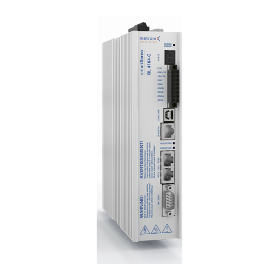
3.2 Device view
Provides a visual overview of the drive's front and rear components.
3.3 Features
Lists key features like fieldbus interfaces, encoder support, and software.
4 Quick-start guide
4.1 Using the parameterisation program
Guides users on how to use the Metronix ServoCommander program.
4.1.1 The user interface
Describes the main window and navigation of the software.
4.1.2 Setting up the communication
Explains how to establish communication via USB or Ethernet.
4.2 Operating mode and error indication
Details how the drive indicates its operating state and errors.
4.3 Operability check
Outlines steps to verify the drive's readiness for operation.
4.4 Software-guided commissioning
Guides users through the initial setup and configuration process.
4.4.1 General configuration
Covers initial application settings like rotary or linear motion.
4.4.2 Configuration of the display unit
Explains how to adapt display units for position, speed, and acceleration.
4.4.3 Adjusting the input limits
Details setting maximum speed and acceleration values for the application.
4.4.4 Configuration of the motor data
Covers entering motor-specific parameters like current and poles.
4.4.5 Safety parameters
Explains drive limitations and monitoring functions for safety.
4.4.6 Motor temperature monitoring
Details configuration for monitoring motor temperature via sensors.
4.4.7 Commutation encoder
Defines the input used for receiving commutation information.
4.4.8 Angle encoder settings
Covers manual configuration of angle encoders connected to X2B.
4.4.9 Angle encoder identification (automatic determination)
Describes automatic determination of encoder parameters like pole pairs.
4.4.10 Automatic identification of the current controller
Explains automatic tuning of the current controller parameters.
4.4.11 Configuring the polarity of the limit switches
Details how to set the logic for limit switch inputs.
4.4.12 Configuration of the speed controller (auto-tuning with FAST)
Guides on automatic tuning of speed controller parameters for optimal performance.
4.4.13 Configuration of the position controller
Explains manual optimization of position controller parameters.
4.4.14 Permanent storage of the parameters
Covers saving configuration parameters to the drive and PC.
5 Enabling the servo drive and selecting the set values
5.1 Configuring the enable logic
Explains how to configure the conditions for enabling the servo drive.
5.2 Operating modes
Details different modes like torque, speed, and positioning control.
5.2.1 Torque-controlled mode (torque control)
Describes operation in torque-controlled mode for specifying target torque.
5.2.2 Speed-controlled mode (speed control)
Explains operation in speed-controlled mode for specifying target speed.
5.2.3 Position-controlled mode and positioning mode (positioning process)
Covers operation where a position controller is active alongside speed control.
5.2.4 Using the servo drive in jog mode
Guides on manual drive movement using arrow buttons for testing.
5.3 Selecting the setpoints
Explains how to select the source for setpoints in torque and speed control.
5.3.1 Specifying the setpoints (speed and torque values)
Details how to enter numerical setpoints and limit values.
5.3.2 Settings concerning the analogue input AIN
Covers configuration of analogue inputs for voltage-to-setpoint conversion.
5.3.3 Offset calibration and "Safe zero"
Explains how to calibrate offset and set a "safe zero" voltage threshold.
6 Applications
6.1 Homing process
Describes automatic zero point determination using various methods.
6.2 Positioning process
Configuring target positions for advance parameterisation.
6.3 Applications with several angle encoders
Discusses using multiple encoders for enhanced position control.
6.4 Flying saw
Explains the "flying saw" function for synchronized movement control.
6.5 Rotary axis mode
Covers configuration for rotary axis applications like indexing tables.
7 Additional settings
7.1 Bluetooth® communication
Details configuring and using the integrated Bluetooth interface.
7.2 Oscilloscope
Explains using the oscilloscope function for signal analysis.
7.3 Display units
Explains adapting display units for application-specific representation.
7.4 Parameter sets
Explains managing parameter sets for configuration and transfer.
7.5 Angle encoder settings
Provides details on configuring various angle encoder interfaces.
7.6 Parameterisation of the motor and output stage
Details methods for analysing motor problems and configuring the output stage.
7.7 Digital inputs
Explains the functions and configuration of the nine digital inputs.
7.8 Digital outputs
Describes the three digital outputs for displaying operating states.
7.9 Position triggers
Explains using position triggers to transfer logic states to digital outputs.
7.10 Brake control and automatic brake
Explains controlling the motor holding brake and automatic brake function.
7.11 Configuration of the DC bus monitoring function
Covers monitoring DC bus voltage for overvoltage and undervoltage.
7.12 External braking resistor
Discusses connecting external braking resistors for increased power dissipation.
7.13 DC bus coupling
Explains coupling DC buses of multiple drives for high braking energy.
7.15 Control circuit cycle times
Details configuring cycle times for internal control circuits.
7.16 Band-stop filters
Explains using band-stop filters to eliminate oscillations in control circuits.
7.17 Motor temperature monitoring system
Covers configuration of motor temperature sensors.
7.19 Firmware download
Guides on updating the servo drive's firmware.
8 STO (safe torque off)
8.1 Special safety instructions
Highlights critical safety instructions for the STO function.
8.2 Certification/safety level
Details the product's safety certifications and levels.
8.3 Requirements for using the product
Outlines prerequisites for using the product safely and legally.
8.3.1 Qualification of the specialist personnel (personnel requirements)
Specifies required qualifications for personnel handling the drive.
8.5 Principle of operation and use
Describes how the STO function operates and is used.
8.5.1 Description of the STO safety function
Explains the STO function's mechanism of safely disconnecting motor power.
8.5.2 Overview of the [X3] interface
Details the 8-pin connector [X3] for STO control and other I/O.
8.5.3 Control inputs STOA, GNDA/STOB, GNDB [X3]
Explains the STOA and STOB inputs for requesting the STO function.
8.5.4 Discrepancy time
Covers the time tolerance for simultaneous actuation of STOA/STOB inputs.
8.6 Circuit examples
Provides circuit examples with detailed drawings for STO functions.
8.6.1 Safe torque off (STO)
Shows a circuit example for connecting the STO function.
8.9 Functional test, validation
Covers functional testing and validation requirements for the STO function.
8.10 Operation
Outlines owner/operator obligations and maintenance for the drive.
8.11 Diagnostics and fault clearance
Explains how the drive indicates states and errors via its display.
9 Fault messages
9.1 Error management
Explains how to define servo drive reactions to various operating states and errors.
9.2 Error buffer
Describes how the error buffer displays occurred errors, warnings, and events.
10 Storage/transport
Storage
Provides guidelines for proper storage of the servo drive.
Transport
Covers safety instructions and precautions for transporting the drive.
Transport damage
Warns about electrical voltage risks due to transport damage.
11 Installation
General installation requirements
Lists requirements for safe and compliant installation of the servo drive.
12 Technical data
12.1 General technical data
Provides ambient conditions, enclosure type, and dimensions.
12.2 Power supply [X9]
Details power data, internal/external braking resistor specifications.
12.3 Motor connector [X6]
Lists performance data, current derating, and motor cable length limits.
12.5 Encoder connector [X2B]
Details technical data for digital incremental and analogue encoders.
12.6 USB [X19]
Specifies communication interface details for USB connection.
12.7 Standard Ethernet [X18]
Lists specifications for the standard Ethernet communication interface.
12.8 Real-time Ethernet [X21]
Details support for EtherCAT and PROFINET fieldbuses.
12.9 CAN bus [X4]
Provides technical data for the CAN bus interface.
12.10 I/O Interface [X1]
Details technical data for digital outputs, digital inputs, and analogue inputs.
12.11 STO [X3]
Lists characteristic values and electrical data for the STO function.
13 Electrical installation
13.1 Notes concerning the safe and EMC compliant installation
Provides information on safe and EMC-compliant installation practices.
13.1.3 Proper wiring
Gives instructions for safe and EMC-compliant wiring.
13.3 Connector: power supply [X9]
Shows connection details for the power supply connector.
13.4 Connector: motor [X6]
Provides pin assignments and cable information for the motor connector.
13.5 Connector: resolvers/analogue Hall encoders [X2A]
Details pin assignments and cable types for resolver/Hall encoders.
13.6 Connector: encoder [X2B]
Covers pin assignments and cable information for various encoder types.
13.7 Connector: USB [X19]
Specifies pin assignments and cable requirements for USB connection.
13.8 Connector: standard Ethernet [X18]
Details pin assignments for the standard Ethernet connector.
13.9 Connector: real-time Ethernet [X21]
Provides pin assignments for real-time Ethernet connectors.
13.10 Connector: CAN bus [X4]
Covers pin assignments and cabling examples for the CAN bus.
13.11 Connector: I/O interface [X1]
Details pin assignments and cable configurations for the I/O interface.
13.12 Connector: STO [X3]
Provides pin assignments and wiring instructions for the STO connector.
14 Maintenance, cleaning, repair and disposal
Maintenance
States that the servo drive is maintenance-free.
Cleaning
Provides guidelines for safe and proper cleaning of the servo drive.
Disposal, removal, decommissioning, replacement
Covers safe decommissioning procedures for the servo drive.
15 Appendix
15.1 CE conformity in accordance with the EMC and Low Voltage Directives
Shows CE declaration regarding EMC and Low Voltage Directives.
15.2 CE conformity in accordance with the Machinery Directive
Displays CE declaration concerning the Machinery Directive compliance.
15.3 cULus certification
Provides the cULus certification details for the product.
15.4 Safety technology glossary
Defines terms and abbreviations used in safety technology.
15.5 Risk reduction questions
Lists questions for validation and risk reduction according to standards.
15.6 Error messages and warnings
Lists and explains various error messages and warnings for troubleshooting.
Need help?
Do you have a question about the smartServo BL 4104-C and is the answer not in the manual?
Questions and answers