Table of Contents

Related Manuals for Metronix ARS 2320 FS


Summary of Contents for Metronix ARS 2320 FS
- Page 1 Metronix Meßgeräte und Elektronik GmbH Kocherstr. 3 38120 Braunschweig Telefon: 0531 8668-0 Telefax: 0531 8668-555 Product Manual / Mounting Instructions Servo drives ARS 2320 FS, ARS 2340 FS and ARS 2360W FS designed for Functional Safety...
- Page 2 Metronix does not guarantee that the products meet the buyer’s demands and purposes or that they work together with other products selected by the buyer. Metronix does not assume any liability for damages resulting from the combined use of its products with other products or resulting from improper handling of machines or systems.
-
Page 3: Table Of Contents
6.6.1 Features .............................. 31 6.6.2 Pin assignment MOV [X40] ......................... 32 6.7 Mechanical installation FSM 2.0 ........................33 Mechanical installation ........................34 Product Manual / Mounting Instructions „Servo drives ARS 2320 FS, ARS 2340 FS and ARS 2360W FS“ Version 1.0... - Page 4 13.2 CE conformity according Machinery directive – MOV ................. 80 13.3 CE conformity according Machinery directive – STO .................. 82 13.4 cULus certification ............................84 Product Manual / Mounting Instructions „Servo drives ARS 2320 FS, ARS 2340 FS and ARS 2360W FS“ Version 1.0...
-
Page 5: General
You can find all these documents on our homepage at the download area www.metronix.de. Certificates and declarations of conformity for the products described in this manual can be found at www.metronix.de. Product Manual / Mounting Instructions „Servo drives ARS 2320 FS, ARS 2340 FS and ARS 2360W FS“ Version 1.0... -
Page 6: Nomenclature
Functional Safety RMS output current Power supply line: 1 = single-phase 3 = three-phase generation Type denomination Figure 1: Type key Product Manual / Mounting Instructions „Servo drives ARS 2320 FS, ARS 2340 FS and ARS 2360W FS“ Version 1.0... -
Page 7: Safety Notes For Electrical Drives And Controllers
– plus the proper and professional electrical installation, operation, and maintenance of the devices. Only trained and qualified personnel is authorised to handle electrical devices and systems: Product Manual / Mounting Instructions „Servo drives ARS 2320 FS, ARS 2340 FS and ARS 2360W FS“ Version 1.0... -
Page 8: Intendend Use
Proper use also includes compliance with all information in this guide. Anything beyond the intended use or otherwise use is considered misuse. Product Manual / Mounting Instructions „Servo drives ARS 2320 FS, ARS 2340 FS and ARS 2360W FS“ Version 1.0... -
Page 9: Danger Resulting From Misuse
Safety glasses To avoid eye injury from dust or splinters. Lightweight respiratory protection To avoid the inhalation of harmful substances. Product Manual / Mounting Instructions „Servo drives ARS 2320 FS, ARS 2340 FS and ARS 2360W FS“ Version 1.0... -
Page 10: Safety Notes
DIN, VDE, EN, IEC or other national and international regulations) must be complied with. Non-compliance may result in death, personal injury or serious property damages. Product Manual / Mounting Instructions „Servo drives ARS 2320 FS, ARS 2340 FS and ARS 2360W FS“ Version 1.0... -
Page 11: Safety Notes For Assembly And Maintenance
Mechanical locking of the vertical axle, External braking, catching or clamping devices or Product Manual / Mounting Instructions „Servo drives ARS 2320 FS, ARS 2340 FS and ARS 2360W FS“ Version 1.0... - Page 12 The servo drive and in particular the brake resistor, externally or internally, can assume high temperatures, which may cause serious burns. Product Manual / Mounting Instructions „Servo drives ARS 2320 FS, ARS 2340 FS and ARS 2360W FS“ Version 1.0...
-
Page 13: Protection Against Contact With Electrical Parts
DC bus or in the case of an unconnected brake resistor, this rapid discharge may be rendered ineffective. The servo drives can carry voltage until up to 10 minutes after being switched off (residual capacitor charge). Product Manual / Mounting Instructions „Servo drives ARS 2320 FS, ARS 2340 FS and ARS 2360W FS“ Version 1.0... -
Page 14: Protection Against Electrical Shock By Means Of Protective Extra-Low Voltage (Pelv)
Random movements or other malfunctions may be caused by switching the safety installations off, by bypassing them or by not activating them. Product Manual / Mounting Instructions „Servo drives ARS 2320 FS, ARS 2340 FS and ARS 2360W FS“ Version 1.0... -
Page 15: Protection Against Contact With Hot Parts
If necessary, use suitable protective equipment (for example goggles, protective footwear, protective gloves). Do not stand underneath hanging loads. Remove leaking liquids on the floor immediately to prevent slipping. Product Manual / Mounting Instructions „Servo drives ARS 2320 FS, ARS 2340 FS and ARS 2360W FS“ Version 1.0... -
Page 16: Product Description
1% per 100 m Humidity Relative humidity up to 90%, no bedewing Protection degree IP20 Protection class Product Manual / Mounting Instructions „Servo drives ARS 2320 FS, ARS 2340 FS and ARS 2360W FS“ Version 1.0... -
Page 17: Mains [X9]
24VDC supply X9B 24 VDC [± 20%] (max. 1 A) *) *) plus current consumption of a possibly connected holding brake and I/Os Product Manual / Mounting Instructions „Servo drives ARS 2320 FS, ARS 2340 FS and ARS 2360W FS“ Version 1.0... -
Page 18: Motor Connector [X6]
Electrical rotational frequency of the motor (speed multiplied by the number of pole pairs) (the higher the rotational frequency is, the longer the permissible time will be) Product Manual / Mounting Instructions „Servo drives ARS 2320 FS, ARS 2340 FS and ARS 2360W FS“ Version 1.0... -
Page 19: Requirements Concerning The Water-Cooler
Evenness of mounting plane of the < = 25 µm @ 100 mm cooler Surface roughness of mounting < = 10 µm plane of the cooler Product Manual / Mounting Instructions „Servo drives ARS 2320 FS, ARS 2340 FS and ARS 2360W FS“ Version 1.0... -
Page 20: Angle Encoder Connector [X2A] And [X2B]
EnDat (Heidenhain), HIPERFACE and HIPERFACE DSL (Sick Stegmann) Output supply 5 V or 12 V; max. 300 mA; currentlimited control via sensor lines Setpoint programmable via software Product Manual / Mounting Instructions „Servo drives ARS 2320 FS, ARS 2340 FS and ARS 2360W FS“ Version 1.0... - Page 21 Resolution: 156,25 µm. Measuring length max. ca. 40 Yaskawa Σ-Encoder Σ (sigma 1) Digital incremental encoder with Yaskawa-OEM-protocol zero-pulse Product Manual / Mounting Instructions „Servo drives ARS 2320 FS, ARS 2340 FS and ARS 2360W FS“ Version 1.0...
-
Page 22: I/O And Communication Interfaces
Parameterisable number of encoder lines/rev lines Trace signals: A, #A, B, #B, N, #N As per RS422 specification Max. input frequency 1000 kHz Product Manual / Mounting Instructions „Servo drives ARS 2320 FS, ARS 2340 FS and ARS 2360W FS“ Version 1.0... - Page 23 SD, SDHC, and MMC, File systems FAT12, FAT16, FAT32 Technology-Module [TECH] PROFIBUS DP, EtherCAT or PROFINET (please ask for separate manual) Product Manual / Mounting Instructions „Servo drives ARS 2320 FS, ARS 2340 FS and ARS 2360W FS“ Version 1.0...
-
Page 24: Function Overview
The position of the DIP switch is read in only once after a reset. Modifications of the switch positions during the operation, therefore, do not affect the current operation. Product Manual / Mounting Instructions „Servo drives ARS 2320 FS, ARS 2340 FS and ARS 2360W FS“ Version 1.0... -
Page 25: Fieldbus Specific Functional Assignment Of The Dip Switches
The control of operating parameters for the RS485 communication that is also supported in the basic device is not possible in favour of the parameterisation of the CAN interface. Product Manual / Mounting Instructions „Servo drives ARS 2320 FS, ARS 2340 FS and ARS 2360W FS“ Version 1.0... - Page 26 DIP switch position = 0 fieldbus configuration based on the parameter set. Can be changed and saved via ® Metronix ServoCommander (downward-compatible). Product Manual / Mounting Instructions „Servo drives ARS 2320 FS, ARS 2340 FS and ARS 2360W FS“ Version 1.0...
-
Page 27: Overview Module Types And Integrated Functional Safety
Angle Shaft Motor speed encoder Communication Safety module FSM 2.0 Figure 2: Schematic representation of the integrated safety technology (MOV) Product Manual / Mounting Instructions „Servo drives ARS 2320 FS, ARS 2340 FS and ARS 2360W FS“ Version 1.0... -
Page 28: Fsm 2.0 - Fba
In addition, the FBA module is required for enabling the driver power supply for the power output stage. Figure 3: FBA module: front view Product Manual / Mounting Instructions „Servo drives ARS 2320 FS, ARS 2340 FS and ARS 2360W FS“ Version 1.0... -
Page 29: Fsm 2.0 - Sto
CAUTION! The function STO as a sole safety function is not sufficient for drives under permanent torque, such as hanging loads. Product Manual / Mounting Instructions „Servo drives ARS 2320 FS, ARS 2340 FS and ARS 2360W FS“ Version 1.0... -
Page 30: Pin Assignment Sto [X40]
The functionality of the DIP switches is identical to the functionality of the DIP switches of the module FSM 2.0 – FBA. Product Manual / Mounting Instructions „Servo drives ARS 2320 FS, ARS 2340 FS and ARS 2360W FS“ Version 1.0... -
Page 31: Fsm 2.0 - Mov
It is exclusively suitable for the ARS 2000 FS product range. ® It offers a user-friendly parameterisation with the Metronix ServoCommander software with including the SafetyTool. Product Manual / Mounting Instructions „Servo drives ARS 2320 FS, ARS 2340 FS and ARS 2360W FS“ Version 1.0... -
Page 32: Pin Assignment Mov [X40]
Digital input 41, two-channel DIN41B DIN43A Digital input 43, two-channel DIN43B DOUT41A Digital output 41, two-channel DOUT41B DOUT42A Digital output 42, two-channel DOUT42B Product Manual / Mounting Instructions „Servo drives ARS 2320 FS, ARS 2340 FS and ARS 2360W FS“ Version 1.0... -
Page 33: Mechanical Installation Fsm 2.0
7. Ensure that the front plate of the safety module module has conducting contact with the housing of the Servo drive. Product Manual / Mounting Instructions „Servo drives ARS 2320 FS, ARS 2340 FS and ARS 2360W FS“ Version 1.0... -
Page 34: Mechanical Installation
In case the servo drives are subject to high thermal stress, a mounting distance of 10 mm between two ARS 2300 FS is recommended! Product Manual / Mounting Instructions „Servo drives ARS 2320 FS, ARS 2340 FS and ARS 2360W FS“ Version 1.0... -
Page 35: Device View Ars 2320 Fs
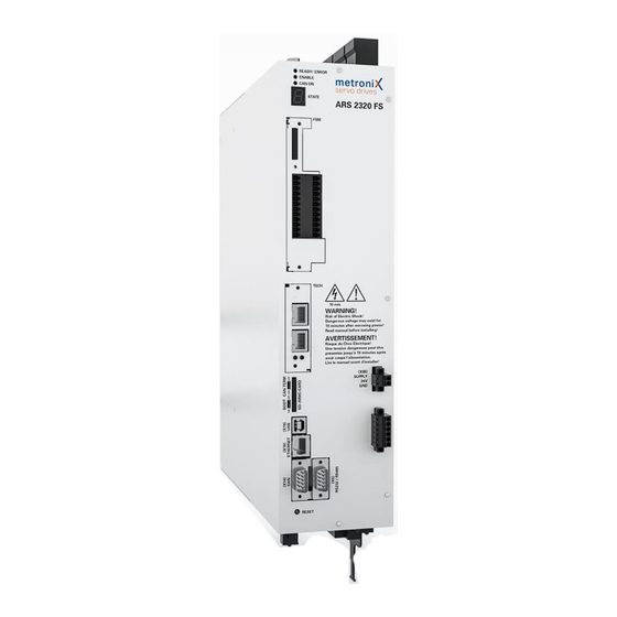
100 - 150 mm free space for sufficient ventilation Figure 6: Servo drive ARS 2320 FS: Front view and Installation space Product Manual / Mounting Instructions „Servo drives ARS 2320 FS, ARS 2340 FS and ARS 2360W FS“ Version 1.0... - Page 36 Incremental encoder input X9C: I/O interface DC bus voltage X9A: Brake resistor Figure 7: Servo drive ARS 2320 FS: Top view Product Manual / Mounting Instructions „Servo drives ARS 2320 FS, ARS 2340 FS and ARS 2360W FS“ Version 1.0...
- Page 37 Motor holding brake X6A: Motor temperature X2B: sensor Multi-Encoder Motor X2A: Resolver Figure 8: Servo drive ARS 2320 FS: Bottom view Product Manual / Mounting Instructions „Servo drives ARS 2320 FS, ARS 2340 FS and ARS 2360W FS“ Version 1.0...
-
Page 38: Installation/Mounting Ars 2320 Fs
Mechanical installation 7.3 Installation/Mounting ARS 2320 FS The Servo drive ARS 2320 FS has attachment lugs on the top and the bottom of the device. These are used to mount the Servo drive vertically to a control cabinet plate. Please use M5 or M6 screws for the mounting of the Servo drive. -
Page 39: Device View Ars 2340 Fs
RESET button 100 mm free space for sufficient ventilation Figure 10: Servo drive ARS 2340 FS: Front view and Installation space Product Manual / Mounting Instructions „Servo drives ARS 2320 FS, ARS 2340 FS and ARS 2360W FS“ Version 1.0... - Page 40 Incremental encoder input X9C: I/O interface DC bus voltage X9A: Brake resistor Figure 11: Servo drive ARS 2340 FS: Top view Product Manual / Mounting Instructions „Servo drives ARS 2320 FS, ARS 2340 FS and ARS 2360W FS“ Version 1.0...
- Page 41 Motor holding brake X6A: Motor temperature X2B: sensor Multi-Encoder X2A: Motor Resolver Figure 12: Servo drive ARS 2340 FS: Bottom view Product Manual / Mounting Instructions „Servo drives ARS 2320 FS, ARS 2340 FS and ARS 2360W FS“ Version 1.0...
-
Page 42: Installation/Mounting Ars 2340 Fs
Mechanical installation 7.5 Installation/Mounting ARS 2340 FS The Servo drive ARS 2320 FS has attachment lugs on the top and the bottom of the device. These are used to mount the Servo drive vertically to a control cabinet plate. Please use M5 or M6 screws for the mounting of the Servo drive. -
Page 43: Device View Ars 2360W Fs
RESET button 100 mm free space for sufficient ventilation Figure 14: Servo drive ARS 2360W FS: Front view and Installation space Product Manual / Mounting Instructions „Servo drives ARS 2320 FS, ARS 2340 FS and ARS 2360W FS“ Version 1.0... - Page 44 Motor holding brake X6A: Motor temperature X2B: sensor Multi-Encoder X2A: Motor Resolver Figure 16: Servo drive ARS 2360W FS: Bottom view Product Manual / Mounting Instructions „Servo drives ARS 2320 FS, ARS 2340 FS and ARS 2360W FS“ Version 1.0...
-
Page 45: Installation/Mounting Ars 2360W Fs
Page 45 7.7 Installation/Mounting ARS 2360W FS The Servo drive ARS 2320 FS has attachment lugs on the top and the bottom of the device. These are used to mount the Servo drive vertically to a water cooling system. Please use M6 screws for the mounting of the Servo drive. -
Page 46: Water Cooling System For Ars 2360W Fs
A-8563 Ligist / Austria Tel.: +43 (0)31 43 23 51-0 Fax: +43 (0)31 43 23 51-14 Mobile: +43 676 6060022 www.dau-at.com Product Manual / Mounting Instructions „Servo drives ARS 2320 FS, ARS 2340 FS and ARS 2360W FS“ Version 1.0... - Page 47 Figure 19: Water cooling system – example by the manufacturer Cool Tec Address: Cool Tec Electronic GmbH Ilmenauer Straße 7 D-98701 Großbreitenbach Tel.: +49 (0)36781 4469-0 Fax: +49 (0)36781 4469-4 www.cooltec.de Product Manual / Mounting Instructions „Servo drives ARS 2320 FS, ARS 2340 FS and ARS 2360W FS“ Version 1.0...
-
Page 48: Electrical Installation
INFORMATION In most cases no external filtering is required Product Manual / Mounting Instructions „Servo drives ARS 2320 FS, ARS 2340 FS and ARS 2360W FS“ Version 1.0... -
Page 49: Proper Emc-Compliant And Secure Cabling
Connect the total shield on the servo drive side and the motor side as described in chapter 8.1 . Connect the total shield on the motor side plane to the connector housing or motor housing; Maximum length 40 mm. Product Manual / Mounting Instructions „Servo drives ARS 2320 FS, ARS 2340 FS and ARS 2360W FS“ Version 1.0... -
Page 50: Operation With Long Motor Cables
Power output stage with a DC bus circuit and mains input Electronic control system for the processing of the analogue signals 24 V supply and digital inputs and outputs Product Manual / Mounting Instructions „Servo drives ARS 2320 FS, ARS 2340 FS and ARS 2360W FS“ Version 1.0... -
Page 51: Wiring Diagram Power Supply [X9, X9A, X9B, X9C] And Motor [X6, X6A, X6B]
/ low side switch Motor feedback [X2A] / [X2B] Resolver / Encoder Motor feedback Figure 20: Connection to power supply [X9] and motor [X6] Product Manual / Mounting Instructions „Servo drives ARS 2320 FS, ARS 2340 FS and ARS 2360W FS“ Version 1.0... -
Page 52: Power Supply [X9, X9A, X9B, X9C]
It is necessary to make an additional PE connection on the cold plate (M4 screw) with the same cross section like the mains supply, see picture in chapter 7. Product Manual / Mounting Instructions „Servo drives ARS 2320 FS, ARS 2340 FS and ARS 2360W FS“ Version 1.0... - Page 53 < 700 VDC Positive DC bus voltage < 700 VDC Negative DC bus voltage < 700 VDC Negative DC bus voltage Product Manual / Mounting Instructions „Servo drives ARS 2320 FS, ARS 2340 FS and ARS 2360W FS“ Version 1.0...
- Page 54 M3: 0,7…0,8 Nm Tightening torque for Mating plug with M4: 1,7...1,8 Nm M4: 1,7...1,8 Nm screws Recommended Circuit Breaker Product Manual / Mounting Instructions „Servo drives ARS 2320 FS, ARS 2340 FS and ARS 2360W FS“ Version 1.0...
-
Page 55: Motor [X6, X6A, X6B]
Motor with holding brake Figure 23: Connecting a holding brake with a high current demand (> 2 A) to the device Product Manual / Mounting Instructions „Servo drives ARS 2320 FS, ARS 2340 FS and ARS 2360W FS“ Version 1.0... - Page 56 Pin No. Denomination Value Specification 24 VDC Motor temperature sensor, normally closed contact, normally open contact, PTC, NTC, KTY Reference potential Product Manual / Mounting Instructions „Servo drives ARS 2320 FS, ARS 2340 FS and ARS 2360W FS“ Version 1.0...
- Page 57 The connections are designed for non-PELV temperature sensors. The isolation to PELV is part inside the ARS 2300 FS. Product Manual / Mounting Instructions „Servo drives ARS 2320 FS, ARS 2340 FS and ARS 2360W FS“ Version 1.0...
- Page 58 M3: 0,7 … 0,8 Nm Tightening torque for M4: 1,7...1,8 Nm M5: 2,5 Nm Mating plug with screws Product Manual / Mounting Instructions „Servo drives ARS 2320 FS, ARS 2340 FS and ARS 2360W FS“ Version 1.0...
-
Page 59: I/O Communication [X1]
24V / 100mA Output freely programmable, optional use as input DIN10 DOUT3 24V / 100mA Output freely programmable, optional use as input DIN11 Product Manual / Mounting Instructions „Servo drives ARS 2320 FS, ARS 2340 FS and ARS 2360W FS“ Version 1.0... - Page 60 100 mA max ! DOUT 3 DOUT x GND24 GND24 GND24 Connector housing Figure 24: Basic circuit diagram of connector [X1] Product Manual / Mounting Instructions „Servo drives ARS 2320 FS, ARS 2340 FS and ARS 2360W FS“ Version 1.0...
- Page 61 Housing for a 25-pin D-SUB connector with locking screws of type 4/40 UNC Recommended cable type or comparable: LAPP KABEL UNITRONIC LiYCY (TP); 25 x 0.25 mm²; 10.7 mm Product Manual / Mounting Instructions „Servo drives ARS 2320 FS, ARS 2340 FS and ARS 2360W FS“ Version 1.0...
-
Page 62: Resolver [X2A]
The three inner shields are connected on one side of the servo drive ARS 2300 FS to Pin 3 of [X2A]. Product Manual / Mounting Instructions „Servo drives ARS 2320 FS, ARS 2340 FS and ARS 2360W FS“ Version 1.0... -
Page 63: Encoder [X2B]
Therefore, start the parameterization software Metronix ServoCommander select Parameters / Device parameters / Angle encoder settings. ® Figure 26: Metronix ServoCommander : Angle encoder settings [X2B] Product Manual / Mounting Instructions „Servo drives ARS 2320 FS, ARS 2340 FS and ARS 2360W FS“ Version 1.0... - Page 64 Male COS_Z0 #COS_Z0 SIN_Z0 #SIN_Z0 Backplane Cable shield Control Cabinet (optional) Connector housing Figure 27: Pin assignment: Analog incremental encoder [X2B] Product Manual / Mounting Instructions „Servo drives ARS 2320 FS, ARS 2340 FS and ARS 2360W FS“ Version 1.0...
- Page 65 Control Cabinet (optional) Connector housing Figure 28: Pin assignment: Incremental encoder with serial communication interface (for example EnDat, HIPERFACE, BiSS) [X2B] Product Manual / Mounting Instructions „Servo drives ARS 2320 FS, ARS 2340 FS and ARS 2360W FS“ Version 1.0...
- Page 66 MT- (AGND) SENSE+ SENSE- Male Backplane Cable shield Control Cabinet (optional) Connector housing Figure 29: Pin assignment: Digital incremental encoder [X2B] Product Manual / Mounting Instructions „Servo drives ARS 2320 FS, ARS 2340 FS and ARS 2360W FS“ Version 1.0...
-
Page 67: Can [X4]
If the bus ends are not formed by ARS 2300 FS servo drive with integrated terminating resistors, we recommend using metal film resistors with a 1% tolerance of type 0207. Product Manual / Mounting Instructions „Servo drives ARS 2320 FS, ARS 2340 FS and ARS 2360W FS“ Version 1.0... - Page 68 X4, Pin 7 (CAN-H) integrated terminating resistor DIP switch CAN TERM X4, Pin 2 (CAN-L) Figure 31: Integrated CAN terminating resistor Product Manual / Mounting Instructions „Servo drives ARS 2320 FS, ARS 2340 FS and ARS 2360W FS“ Version 1.0...
- Page 69 For highly flexible applications: LAPP KABEL UNITRONIC BUS CAN FD P; 2 x 2 x 0.25; 8.4 mm, with CU overall shielding Product Manual / Mounting Instructions „Servo drives ARS 2320 FS, ARS 2340 FS and ARS 2360W FS“ Version 1.0...
-
Page 70: Rs232 [X5]
Housing for a 9-pin D-SUB connector with locking screws of type 4/40 UNC Recommended cable type or comparable: Interface cable for the serial interface (null modem), 3 cores Product Manual / Mounting Instructions „Servo drives ARS 2320 FS, ARS 2340 FS and ARS 2360W FS“ Version 1.0... -
Page 71: Incremental Encoder Input [X10]
RS422 interface standard. Processing of other signals and levels (e.g. 5 V single-ended or 24 V of a PLC) may also be possible. Please contact your sales partner. Product Manual / Mounting Instructions „Servo drives ARS 2320 FS, ARS 2340 FS and ARS 2360W FS“ Version 1.0... -
Page 72: Incremental Encoder Output [X11]
ARS 2000 FS, X10) Incremental encoder output Male Cable shield Connector housing (optional) Connector housing Figure 34: Pin assignment: Incremental encoder output [X11] Product Manual / Mounting Instructions „Servo drives ARS 2320 FS, ARS 2340 FS and ARS 2360W FS“ Version 1.0... -
Page 73: Ethernet Communication [X18]
Pair 1 Pair 1 Receiver signal- ( RX- ) Pair 2 Pair 4 Pair 4 Figure 35: Pin assignment: Ethernet interface [X18] Product Manual / Mounting Instructions „Servo drives ARS 2320 FS, ARS 2340 FS and ARS 2360W FS“ Version 1.0... -
Page 74: Usb Communication [X19]
USB Isolator" (Type 62588 from Delock) or one comparable adapter. Pin assignment X19 USB Pin No. Specification Data - Data + Figure 36: Pin assignment: USB interface [X19] Product Manual / Mounting Instructions „Servo drives ARS 2320 FS, ARS 2340 FS and ARS 2360W FS“ Version 1.0... -
Page 75: Sd/Sdhc/Mmc Card Slot
Data line 0 (bit 0) Card to host data and status DAT1 Data line 1 (bit 1) Reserved DAT2 Data line 2 (bit 2) Reserved Product Manual / Mounting Instructions „Servo drives ARS 2320 FS, ARS 2340 FS and ARS 2360W FS“ Version 1.0... -
Page 76: Boot-Dip-Switch
“ON” (firmware download requested), the error 29-0 is triggered after a restart/reset. This error stops all further performances. This means that there is no communication possible via USB. Product Manual / Mounting Instructions „Servo drives ARS 2320 FS, ARS 2340 FS and ARS 2360W FS“ Version 1.0... -
Page 77: Additional Requirements For The Servo Drives Concerning The Ul Approval
The sensor has to be connected to the servo drive and the temperature monitoring has to be activated accordingly on the software side. Product Manual / Mounting Instructions „Servo drives ARS 2320 FS, ARS 2340 FS and ARS 2360W FS“ Version 1.0... -
Page 78: Start-Up
Please see documentation of the servo drives ARS 2302 FS – ARS 2310 FS. Technology modules Please see documentation of the servo drives ARS 2302 FS – ARS 2310 FS. Product Manual / Mounting Instructions „Servo drives ARS 2320 FS, ARS 2340 FS and ARS 2360W FS“ Version 1.0... -
Page 79: Appendix
Appendix Page 79 Appendix 13.1 CE conformity according EMC- , Low voltage and RoHS directive Product Manual / Mounting Instructions „Servo drives ARS 2320 FS, ARS 2340 FS and ARS 2360W FS“ Version 1.0... -
Page 80: Ce Conformity According Machinery Directive - Mov
Page 80 Appendix 13.2 CE conformity according Machinery directive – MOV Product Manual / Mounting Instructions „Servo drives ARS 2320 FS, ARS 2340 FS and ARS 2360W FS“ Version 1.0... - Page 81 Appendix Page 81 Product Manual / Mounting Instructions „Servo drives ARS 2320 FS, ARS 2340 FS and ARS 2360W FS“ Version 1.0...
-
Page 82: Ce Conformity According Machinery Directive - Sto
Page 82 Appendix 13.3 CE conformity according Machinery directive – STO Product Manual / Mounting Instructions „Servo drives ARS 2320 FS, ARS 2340 FS and ARS 2360W FS“ Version 1.0... - Page 83 Appendix Page 83 Product Manual / Mounting Instructions „Servo drives ARS 2320 FS, ARS 2340 FS and ARS 2360W FS“ Version 1.0...
-
Page 84: Culus Certification
Page 84 Appendix 13.4 cULus certification on request Product Manual / Mounting Instructions „Servo drives ARS 2320 FS, ARS 2340 FS and ARS 2360W FS“ Version 1.0...
Need help?
Do you have a question about the ARS 2320 FS and is the answer not in the manual?
Questions and answers