Metronix smartServo BL 4000-C Mounting Instructions
Hide thumbs
Also See for smartServo BL 4000-C:
- Product manual (298 pages) ,
- Mounting instructions (36 pages)

Related Manuals for Metronix smartServo BL 4000-C


Summary of Contents for Metronix smartServo BL 4000-C
- Page 1 Mounting Instructions BL 4000-C smartServo Important! Read thoroughly before use! Retain for future reference!
- Page 2 However, deviations between the document and the product cannot be excluded entirely. For the devices and the corresponding software in the version handed out to the customer, Metronix guarantees the contractual use in accordance with the user documentation. In the case of serious deviations from the user documentation, Metronix has the right and the obligation to repair, unless it would involve an unreasonable effort.
- Page 3 Contact Metronix Meßgeräte und Elektronik GmbH Kocherstraße 3 38120 Braunschweig Germany Telephone: +49 (0)531 8668 0 Fax: +49 (0)531 8668 555 E-mail: vertrieb@metronix.de https://www.metronix.de Revision Information Manual title Mounting Instructions "BL 4000-C" File name MI_BL 4000-C_1p1_EN.pdf Version Year 2022 Mounting Instructions BL 4000-C...
-
Page 4: Table Of Contents
Table of Contents 1 About this Mounting Instructions 1.1 Explanations and notation 1.1.1 Structure of the warning notes 1.1.2 Structure of notes 1.2 Additional documents 1.3 Order numbers 1.4 Applicable standards 2 For your own safety 2.1 General information 2.2 Intended use 2.3 Target group 2.4 General safety instructions 2.5 Personal protective equipment... - Page 5 5.14 Connector: STO [X3] 6 Technical data 6.1 General technical data 6.2 BL 4100-C: Power supply [X9] 6.3 BL 4300-C: Power supply [X9], [X9A], [X9B] 6.4 BL 4100-C: Motor connector [X6] 6.5 BL 4300-C: Motor connector [X6], [X6A] 6.6 Resolver connector [X2A] 6.7 Encoder connector [X2B] 6.8 USB [X19] 6.9 Standard Ethernet [X18] 6.10 Realtime-Ethernet [X21]...
-
Page 6: About This Mounting Instructions
The purpose of these Mounting Instructions is to ensure the safe installation and proper wiring of the servo drives of the smartServo BL 4000-C series. The safe use of the servo ® drive and of the Metronix ServoCommander parameterisation program is described in the Product manual smartServo BL 4000-C. -
Page 7: Structure Of Notes
BL 4000-C, as well as safe working with the servocontroller and the parameterisation program ® Metronix ServoCommander EtherCAT and CANopen manual BL 4000: This manual describes the commissioning procedure for the servo drives ARS 2000 FS or BL 4000 with a CANopen or EtherCAT control system. - Page 8 1 About this Mounting Instructions Standard Description EN 50581 Technical documentation for the assessment of electrical and electronic products with respect to the restriction of hazardous substances EN 60204-1 Safety of machinery - Electrical equipment of machines - Part 1: General requirements EN 61800-3 Adjustable speed electrical power drive systems - Part 3: EMC...
-
Page 9: For Your Own Safety
2 For your own safety For your own safety Servo drives of the BL 4000-C series can only be used safely, if you read and comply with this document. General information The servo drive has a safe design. However, certain hazards exist in the context of certain activities. -
Page 10: Intended Use
2 For your own safety Intended use The electronic drive control unit (servo drive) is intended for operation in combination with electric motors in an industrial environment. The handling of the servo drive requires qualified personnel that have been trained in terms of general and, in particular, electrical safety. -
Page 11: General Safety Instructions
2 For your own safety General safety instructions Danger to life due to electric shock! Non-compliance with the safety instructions will lead to a potentially fatal electric shock. The general set-up and safety rules and regulations concerning the work on power installations (e.g. -
Page 12: Personal Protective Equipment
2 For your own safety Personal protective equipment Always use personal protective equipment during the transport, installation, start-up, cleaning, maintenance and removal of the servo drive, for example: Protective gloves To prevent superficial hand injuries. ESD safety shoes To prevent foot injuries caused by falling parts. To prevent electrostatic charging. - Page 13 2 For your own safety To prevent accidents, injuries and damage to property: Perform a risk assessment and follow all of the statutory and local safety instructions and accident prevention regulations when installing or maintaining the system. Ensure that the AC or DC power supplies are switched off and locked prior to performing any work in the area of the machine.
-
Page 14: Protection Against Contact With Electrical Parts
2 For your own safety Protection against contact with electrical parts Dangerous electrical voltage! In certain device constellations, the rapid discharge of the DC bus voltage of the servo drive may be rendered ineffective. In these cases, the servo drives may still carry dangerous voltage levels for a very long time after they have been switched off (residual capacitor charge). -
Page 15: Protection Against Electric Shock By Way Of Protective Extra-Low Voltage (Pelv)
2 For your own safety Protection against electric shock by way of protective extra-low voltage (PELV) Dangerous electrical voltage! There is a risk of high electrical voltage due to incorrect electrical connections. Always follow the safety instructions stated hereinbelow. All of the connections and terminals with voltages up to 50 V of the servo drive have protective extra-low voltage. -
Page 16: Protection Against Contact With Hot Parts
2 For your own safety 2.10 Protection against contact with hot parts Risk of burns due to hot surfaces The servo drive and, in particular, the (external or internal) braking resistor may become hot during operation. Always wait a sufficient amount of time prior to touching these parts. -
Page 17: Product Description
3 Product description Product description The servo drives of the smartServo BL 4000-C series are smart AC servo drives for controlling three-phase synchronous motors, torque motors and linear motors. The servo drives can be used in a universal manner, since they can be combined with a wide range of encoder systems and motors. -
Page 18: Device View
3 Product description Device view Front view Figure 2: Front view of a BL 4100-C (left) and a BL 4300-C (right) 01 Product name 08 LED (RUN/SF/MS) 02 Earthing screw 09 LED (ERR/BF/MS) 03 Status indicator LED 10 [X21] Real-time Ethernet interface (READY, ERROR, ENABLE) 04 Seven-segment status indicator 11 [X4] CANopen interface... - Page 19 3 Product description Top view Figure 3: Top view of a BL 4100-C (left) and a BL 4300-C (right) 14 [X9] Power supply 17 [X1] I/O communication 15 [X9A] Braking resistor (BL 4300-C) 18 Slot for microSD cards 16 [X9B] 24 V supply (BL 4300-C) Bottom view Figure 4: Bottom view of a BL 4100-C (left) and a BL 4300-C (right) ®...
-
Page 20: Features
All of the servo drives of this series have the following features: Integrated fieldbus interfaces CANopen interface EtherCAT interface (CoE) PROFINET interface (Metronix standard telegrams, based on PROFIdrive) Integrated universal shaft encoder evaluation for the following encoder types: Resolvers Analogue and digital incremental encoders with and without commutation signals ®... - Page 21 3 Product description Integrated functional safety "Safe Torque Off (STO)" safety function integrated in the device SS1 functionality possible Homing and positioning Integrated positioning control with a wide range of functions as per "CAN in Automation (CiA) DSP402" plus numerous additional application-specific functions.
- Page 22 3 Product description Applications Speed- and angle-synchronous operation with an electronic gear unit via the incremental encoder input or fieldbus. Extensive modes of operation for synchronisation, e.g. "flying saw" Jog mode, teach-in mode, motion programs, torque-limited set control and much more Special control features High control quality due to high-quality sensors, far superior to conventional market...
-
Page 23: Mounting
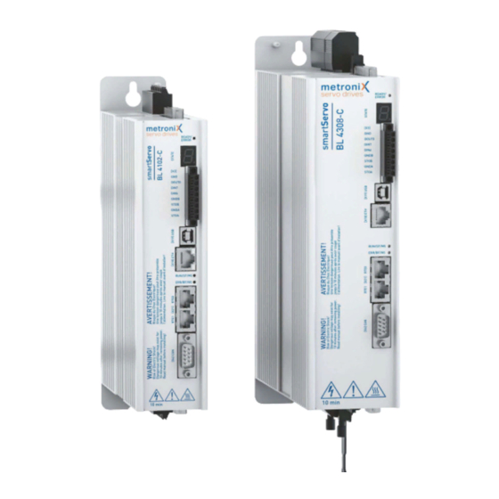
4 Mounting Mounting Figure 5: Servo drive BL 4100-C (left) and BL 4300-C (right) Mounting Instructions BL 4000-C Page 23 of 89... - Page 24 4 Mounting The following requirements must be fulfilled for the installation of the servo drive: Follow the general set-up and safety rules and regulations concerning the installation. Follow the safety instructions in section 2.6 Safety notes for installation and maintenance on page 12. Use only suitable tools.
-
Page 25: Electrical Installation
5 Electrical installation Electrical installation This chapter provides all of the relevant information for the electrical installation of a servo drive of the BL 4000-C series with an integrated "Safe Torque Off (STO)" safety function. Notes concerning the safe and EMC- compliant installation 5.1.1 Explanations and terminology... -
Page 26: Proper Wiring
5 Electrical installation 5.1.3 Proper wiring The following must be observed for servo drives of type BL 4000-C to ensure a safe and EMC-compliant design of the drive system: Dangerous electrical voltage! For safety reasons, all of the PE earth (ground) conductors must be connected prior to the initial operation of the system. -
Page 27: Operation With Long Motor Cables
5 Electrical installation 5.1.4 Operation with long motor cables Compliance with the EMC standard EN 61800-3 Compliance with the EMC standard EN 61800-3 is ensured only for a motor cable length of 25 m maximum. Operation with longer cables is not permissible. In applications where long motor cables are required or when using motor cables with unacceptably high cable capacitance, the filters, the power amplifier and the sensors may be overloaded. -
Page 28: Additional Requirements For The Ul Approval
5 Electrical installation Additional requirements for the UL approval Mains power supply protection Integral solid state short circuit protection does not provide branch circuit protection. Branch circuit protection must be provided in accordance with the Manufacturer Instructions, National Electrical Code and any additional local codes. BL 4100-C: Suitable For Use On A Circuit Capable Of Delivering Not More Than 5,000 rms Symmetrical Amperes, 240 Volts Maximum When Protected by A Circuit Breaker... -
Page 29: Connector Bl 4100-C: Power Supply [X9]
5 Electrical installation Connector BL 4100-C: power supply [X9] Servo drives of the BL 4100-C series must be connected to the voltage supply and an optional brake resistor in accordance with the following illustration. Figure 6: Connection of a BL 4100-C to the power supply [X9] Risk of damage to the servo drive The servo drive will be damaged in the following cases: reverse connection of the 24 V operating voltage connections,... - Page 30 5 Electrical installation Configuration on the device [X9] Weidmüller SL 5.08HC/09/90G 3.2SN BK BX Mating connector [X9] Weidmüller BLF 5.08HC/09/180 SN BK BX Pin assignment [X9] Figure 7: Pin assignment: „power supply connector [X9]“ Name Specification Supply voltage reference potential Supply voltage for the control module and holding brake Connection of the protective earth (ground) conductor of the mains power supply R_CH...
-
Page 31: Connector Bl 4300-C: Power Supply [X9], [X9A], [X9B]
5 Electrical installation Connector BL 4300-C: power supply [X9], [X9A], [X9B] Servo drives of the BL 4300-C series must be connected to the voltage supply and an optional brake resistor in accordance with the following illustration. Figure 8: Connection of a BL 4300-C to the power supply [X9] Risk of damage to the servo drive The servo drive will be damaged in the following cases: reverse connection of the 24 V operating voltage connections,... - Page 32 5 Electrical installation brake chopper and an internal braking resistor. If this is used, a bridge must be wired to [X9A]. For more braking power, an external braking resistor can be connected to the connector [X9A] instead of the bridge. The servo drive must be connected to earth (ground) with its PE connectors (Please also refer to section 5.1.3 Proper wiring on page 26).
- Page 33 5 Electrical installation Pin X9 Name Specification Pos. DC bus voltage Neg. DC bus voltage Connection of the protective earth (ground) conductor of the mains power supply Phase conductor/mains phase 3 Phase conductor/mains phase 2 Phase conductor/mains phase 1 Pin X9A Name Specification R_INT Internal braking resistor connection...
-
Page 34: Connector Bl 4100-C: Motor [X6]
5 Electrical installation Connector BL 4100-C: motor [X6] The motor is connected to the terminals U,V,W. An analog motor temperature sensor can be connected to the terminals MT+ and MT- if it is routed together with the motor phases in one cable. - Page 35 5 Electrical installation ® Pin assignment: motor with HIPERFACE DSL ® Figure 11: Pin assignment: motor connector (HIPERFACE DSL ) [X6] Name Specification Motor phase U Motor phase V Motor phase W Protective earth conductor of the motor MT-/ DSL- HIPERFACE DSL - DSL+ HIPERFACE DSL + Holding brake +...
- Page 36 5 Electrical installation Connection notes [X6] Connect the inner and outer cable shield with the greatest possible surface area to the back panel of the control cabinet by way of suitable EMC terminals (e.g. icotek LFZ/SKL, SFZ/SKL or PFSZ-MSKL). The unshielded cable end should not be longer than 80 mm. An existing holding brake in the motor must be connected to the terminals BR+ and BR-.
-
Page 37: Connector Bl 4300-C: Motor [X6], [X6A]
5 Electrical installation Connector BL 4300-C: motor [X6], [X6A] The motor is connected to the terminals U,V,W. An analog motor temperature sensor can be connected to the terminals MT+ and MT- if it is routed together with the motor phases in one cable. - Page 38 5 Electrical installation Pin X6A Name Specification Motor temperature sensor + MT-/ DSL- Motor temperature sensor - DSL+ Holding brake + Holding brake - ® Pin assignment [X6], [X6A]: motor with HIPERFACE DSL ® Figure 13: Pin assignment: motor connector (HIPERFACE DSL ) [X6] Pin X6 Name Specification...
- Page 39 5 Electrical installation Device type Cable type Specification (U, V, W, PE) BL 4304-C 4 G 1,0 + 2 x (2 x 0,75) 4 x 1,0 mm² (AWG 18) BL 4308-C 4 G 1,5 + 2 x (2 x 0,75) 4 x 1,5 mm² (AWG 16) BL 4312-C 4 G 2,5 + 2 x (2 x 1,0) 4 x 2,5 mm²...
-
Page 40: Connector: Resolvers/Analogue Hall Encoders [X2A]
5 Electrical installation Connector: resolvers/analogue Hall encoders [X2A] Two different encoder types can be connected to the 9-pin D-Sub connector: Resolvers Analogue Hall generators with tracks that are offset by 90° (sine/cosine) Diverging from the analogue evaluation via the X2B interface, this input has a higher resolution and it is possible to read in higher amplitudes. - Page 41 5 Electrical installation Name Specification SINE track signal, differential Analogue Hall sensor (SINE) COSINE track signal, differential Analogue Hall sensor (COSINE) Shield for signal pairs (inner shield) Temperature sensor reference potential Carrier signal for the resolver Motor temperature sensor, normally closed contact, PTC, NTC, Only one motor temperature sensor can be connected The motor temperature sensor can either be connected to X2A, X2B or X6.
-
Page 42: Connector: Encoder [X2B]
If an incorrect power supply is used, the encoder may be destroyed. Ensure that the correct voltage is activated prior to connecting the encoder to [X2B]. To do so, start the ® Metronix ServoCommander parameterisation software and select the Parameters/Device parameters/Angle encoder settings. - Page 43 5 Electrical installation Pin assignment: analogue incremental encoders Figure 16: Pin assignment: analogue incremental encoders [X2B] Name Specification Motor temperature sensor, normally closed contact, PTC, NTC, KTY U_SENS+ Sensor cables for the encoder supply. In case of long cables, connect to US/GND at the motor U_SENS- end.
- Page 44 5 Electrical installation Pin assignment: incremental encoder with a serial interface Figure 17: Pin assignment: incremental encoder with a serial interface [X2B] Name Specification Motor temperature sensor, normally closed contact, PTC, NTC, KTY U_SENS+ Sensor cables for the encoder supply. In case of long cables, connect to US/GND at the motor end.
- Page 45 5 Electrical installation Pin assignment: digital incremental encoder (RS422) Figure 18: Pin assignment: digital incremental encoder (RS422) [X2B] Name Specification Motor temperature sensor, normally closed contact, PTC, NTC, KTY U_SENS+ Sensor cables for the encoder supply. In case of a long cable, connect to US/GND at the motor end.
-
Page 46: Connector: Usb [X19]
5 Electrical installation Connector: USB [X19] The BL 4000-C servo drive has a Type B USB connector. The correct operation requires a short USB cable (< 3 m) and the correct installation and earthing of the servo drive. If excessive malfunctions/faults lead to communication problems (frozen communication), the USB connector can be briefly disconnected to restart the communication. -
Page 47: Connector: Standard Ethernet [X18]
5 Electrical installation 5.10 Connector: standard Ethernet [X18] The BL 4000-C servo drive has a network connector of the RJ45 type. Configuration on the device [X18] Female RJ45 connector, cat. 6 Mating connector [X18] Male RJ45 connector Pin assignment of the network connector [X18] Cat.6 patch cable RJ45 LAN cable S-FTP/PIMF. -
Page 48: Connector: Real-Time Ethernet [X21]
5 Electrical installation 5.11 Connector: real-time Ethernet [X21] The connection to an EtherCAT or PROFINET network must be realised via two female RJ45 connectors. Details can be found in the Fieldbus manuals. Configuration on the device [X21] Female RJ45 connector, cat. 6 Mating connector [X21] Male RJ45 connector Pin assignment of the real-time Ethernet connector [X21]... -
Page 49: Connector: Can Bus [X4]
5 Electrical installation 5.12 Connector: CAN bus [X4] For trouble-free operation of the CAN bus communication, the following instructions must be observed Ideally, the individual nodes of the networks are always connected in a linear manner so that the CAN cable is looped through from servo drive to servo drive. A terminating resistor of 120 Ω, 5%, must be present on both ends of the CAN bus cable We advise against the use of intermediate plugs for cabling the CAN bus. - Page 50 5 Electrical installation Configuration on the device [X4] D-SUB connector, 9-pin type, male Mating connector [X4] D-SUB connector, 9-pin type, female Housing for a 9-pin D-SUB connector with locking screws of type 4/40 UNC Pin assignment [X4] Name Specification Not used CAN-GND, directly coupled to GND in the servo drive CANL CAN low signal line...
-
Page 51: Connector: I/O Interface [X1]
5 Electrical installation 5.13 Connector: I/O interface [X1] The BL 4000-C servo drive has two differential inputs (AIN) for analogue input voltages in the range of ± 10 V.The inputs AIN and #AIN are connected to the control system via twisted cables (twisted-pair type). Alternatively, it is also possible to use a shielded cable. If the control system is equipped with single-ended outputs, the output is connected to AIN and #AIN is connected to the reference potential of the control system. - Page 52 5 Electrical installation Pin assignment [X1] Name Specification #AIN1 Analogue input 1, input voltage 30 V max. AIN1 #AIN0 Analogue input 0, input voltage 30 V max. AIN0 A / CLK Incremental encoder signal A/stepper motor signal CLK #A / CLK Incremental encoder signal #A/stepper motor signal CLK B / DIR Incremental encoder signal B/stepper motor signal DIR...
-
Page 53: Connector: Sto [X3]
5 Electrical installation 5.14 Connector: STO [X3] Dangerous electrical voltage! Use only PELV circuits for the STO wiring! Make sure that no jumpers or the like can be inserted parallel to the safety wiring. For example, use the maximum wire cross-section of 1.5 mm² or suitable wire end sleeves with insulating collars for the connection to the associated connector. - Page 54 5 Electrical installation Cable type and configuration [X3] Characteristic Value Max. cable length, unshielded 30 m Max. cable length, shielded > 30 m Shielding In the case of wiring outside the control cabinet and with cable lengths > 30 m, the shield must be led into the control cabinet.
-
Page 55: Technical Data
6 Technical data Technical data This chapter provides all of the relevant technical data of the BL 4000-C servo drives with an integrated "Safe Torque Off (STO)" safety function. General technical data Qualification Characteristic Value Low Voltage Directive 2014/30/EU by applying the harmonised standard EN 61800-5-1 See section 9.1 CE conformity (EMC, RoHS, Low Voltage Directive) on page 82... - Page 56 6 Technical data Compliance with the pollution degree rating The integrated safety technology requires compliance with pollution degree rating 2 and thus a protected enclosure (IP54). This must always be ensured through appropriate measures, e.g. through installation in a control cabinet. Use in residential environment In a residential environment, servo drives of the BL 4000-C device family can cause high-frequency interference, which makes interference suppression measures...
-
Page 57: Bl 4100-C: Power Supply [X9]
6 Technical data BL 4100-C: Power supply [X9] Power data Characteristic BL 4102-C BL 4104-C Supply voltage 1 x 75 ... 230 VAC [± 10 %], 50 ... 60 Hz Supply network type TN, TT Maximum mains current in continuous operation (S1) * DC bus voltage 325 VDC (with U = 230 VAC) -
Page 58: Bl 4300-C: Power Supply [X9], [X9A], [X9B]
6 Technical data BL 4300-C: Power supply [X9], [X9A], [X9B] Power data Characteristic BL 4304-C BL 4308-C BL 4312-C Supply voltage 3 x 230 ... 480 VAC [± 10 %], 45 ... 66 Hz Supply network type TN, TT Maximum mains current in 12 A continuous operation (S1) DC bus voltage... -
Page 59: Bl 4100-C: Motor Connector [X6]
6 Technical data BL 4100-C: Motor connector [X6] Performance data With supply voltage 230 VAC [± 10 %], 50 Hz, f = 10 kHz, f > 2 Hz Characteristic BL 4102-C BL 4104-C Nominal output power 400 W 800 W Maximum output power for 2 s 1 kW 2 kW Nominal output current... - Page 60 6 Technical data Motor cable requirements Characteristic Value Cable length l ≤ 25 m See section 5.1 Notes concerning the safe and EMC- compliant installation on page 25 Cable capacity C‘ ≤ 160 pF/m of one phase against shield or between two lines Motor temperature monitoring system Dangerous electrical voltage! The signals for the temperature sensor "MT-"...
- Page 61 6 Technical data ® HIPERFACE DSL connector [X6] Characteristic Value HPF_DSL-, HPF_DSL+ In accordance with the ® HIPERFACE DSL specification RS485 Baud rate 9.37 MHz Frame rate 12.1 to 27 µs Supply voltage 10 V (250 mA) Supported transfer modes Transfer of short and long messages with storage of the set of parameters in the encoder Characteristic impedance of the cable and line...
-
Page 62: Bl 4300-C: Motor Connector [X6], [X6A]
6 Technical data BL 4300-C: Motor connector [X6], [X6A] Performance data Supply voltage 400 VAC [± 10%], 50 Hz, f = 8 kHz, f > 3 Hz Characteristic BL 4304-C BL 4308-C BL 4312-C Nominal output power 1,6 kW 3,2 kW 4,8 kW Maximum output power for 2 s 4,8 kW... - Page 63 6 Technical data Motor cable requirements Characteristic Value Cable length l ≤ 25 m See section 5.1 Notes concerning the safe and EMC-compliant installation on page 25 Cable capacity C‘ ≤ 160 pF/m of one phase against shield or between two lines Motor temperature monitoring system Dangerous electrical voltage! The signals for the temperature sensor "MT-"...
-
Page 64: Resolver Connector [X2A]
6 Technical data ® HIPERFACE DSL connector [X6] Characteristic Value ® HPF_DSL-, HPF_DSL+ In accordance with the HIPERFACE DSL specification RS485 Baud rate 9.37 MHz Frame rate 12.1 to 27 µs Supply voltage 10 V (250 mA) Supported transfer modes Transfer of short and long messages with storage of the set of parameters in the encoder Characteristic impedance of the cable 110 Ω... -
Page 65: Encoder Connector [X2B]
6 Technical data Encoder connector [X2B] The correct parameterisation of the multi-encoder interface is described in section „X2B/X6“ tab in the Product manual smartServo BL 4000-C. Possibly not all encoders of a manufacturer are supported It is possible that not all encoders of a manufacturer are fully supported. In individual cases it is therefore always recommended to test the encoder in advance in the intended application. - Page 66 6 Technical data Analogue incremental encoders with commutation signals Analogue incremental encoders with RS422-compatible 1 V signals (e.g. ERN 1387) can be connected. Characteristic Value Parameterisable number of encoder lines 1 to 2 lines/revolution High position resolution of the AB track 12 bits/period (Z0) and commutation track (Z1) Track signals A, B (Z0 track)
- Page 67 6 Technical data In addition, the following Sick-Stegmann encoder systems can be connected and evaluated: Absolute, non-contact length measuring systems L230 and TTK70 ® (HIPERFACE Digital incremental encoder CDD 50 Characteristic Value Parameterisable number of encoder lines Depending on the encoder Track signals A, B (Z0 track) As per RS485 Input: 0.4 V, output: 0.8 V to 2 V...
-
Page 68: Usb [X19]
The support of these fieldbus types is integrated in the servo drive. Additional modules are not required. The parameterisation is performed with the aid of the ® Metronix ServoCommander . For further information about the fieldbus connection, see the fieldbus-specific product manuals section 1.2 Additional documents on page 7). -
Page 69: I/O Interface [X1]
6 Technical data 6.12 I/O Interface [X1] Servo drives of the BL 4000-C series have 3 digital outputs (DOUT), 9 digital inputs (DIN) and 2 analogue inputs (AIN). Digital outputs Characteristic Value Nominal voltage 24 V Output current Approx. 1 A per output, but 2.5 A max. in total, including the brake output Digital inputs Characteristic... - Page 70 6 Technical data Analogue input AIN1 Characteristic Value Input range ± 10 V Resolution 12 bits Filter time 4 x t corresponds to the configurable current controller cycle time Master frequency input [X1] This input cannot only be used for the connection of the master frequency output of another BL 4000-C , BL 4000-M / BL 4000-D.
- Page 71 6 Technical data circuits must be suitable for incremental encoders. As a result, the measurement of gate times or the analysis of the time between two lines for determining a speed value is possible only to a limited extent. Mounting Instructions BL 4000-C Page 71 of 89...
-
Page 72: Time Response Of The Digital Inputs
6 Technical data 6.12.1 Time response of the digital inputs The digital inputs are digitally filtered to improve the interference suppression. The following illustration shows the filter time mechanism. In addition, the special reaction to the "Positioning start" function is also shown. Although the signal is evaluated during the position controller cycle t the start of a movement will be performed within the interpolation cycle time matrix t... -
Page 73: Time Response Of The Digital Outputs
6 Technical data 6.12.2 Time response of the digital outputs Figure 25: Filter time mechanism in the case of digital outputs Parameter Value Delay caused by the firmware t DOUT_ON DOUT_OFF DOUT t typically 100 µs HW, ON DOUT t typically 300 µs HW, OFF typically 100 ms with 2 A RISE... -
Page 74: Time Response During Power On
6 Technical data 6.12.3 Time response during power ON Figure 26: Time diagram of the servo drive Parameter Min. Typ. Max. Start of the firmware after power ON t boot Encoder start time t 0.7 s ® (resolver) (HIPERFACE DSL DC bus charging time t Output stage active after servo drive 6 ms enabling t... -
Page 75: Sto [X3]
6 Technical data 6.13 STO [X3] Characteristic values Characteristic Value Safety level Category 4 and performance level e or SIL3/SIL CL3. –11 PFH (probability of dangerous failure per hour) 3 x 10 PFD (probability of dangerous failure on demand) 5 x 10 DCavg (average diagnostic coverage) High MTTFd (mean time to dangerous failure) -
Page 76: Time Response
6 Technical data Response time until power output stage inactive and maximum OSSD test pulse duration The typical response time and the maximum test pulse duration depend on the input voltage at STOA/STOB: Characteristic Value Input voltage (STOA/STOB) 19.2 V 24 V 28.8 V Typical response time... - Page 77 6 Technical data Figure 27: Time response of the activation of the STO safety function with a restart see section 0.1 Operating mode and error indication of the servo drive on page 1 Time Description Value Maximum permissible discrepancy time 100 ms DCRP without the servo drive issuing an error...
-
Page 78: Time Response Of The Ss1 Activation During Operation With A Restart
6 Technical data 6.13.2.2 Time response of the SS1 activation during operation with a restart Figure 28: Time response during the activation of the SS1 safety function (external switching) with a restart see section 0.1 Operating mode and error indication of the servo drive on page 1 Mounting Instructions BL 4000-C Page 78 of 89... -
Page 79: Microsd Card
6 Technical data Time Description Value Delay between the switching of S1 and the See the data sheet of the closing of the undelayed contact K1 safety relay Delay between S1 and the opening of the off- Can be adjusted on the K1_delay delayed contacts K1 safety relay... -
Page 80: Storage/Transport
7 Storage/transport Storage/transport The following requirements must be fulfilled for the storage and transport of the servo drive: Storage Store the servo drive in line with the specified storage temperatures. Use only its original packaging. After approximately six months of storage, the oxide layer of the capacitors may become damaged. -
Page 81: Maintenance, Cleaning, Repair And Disposal
8 Maintenance, cleaning, repair and disposal Maintenance, cleaning, repair and disposal The following requirements must be fulfilled for the maintenance, cleaning, repair and disposal of the servo drive: Maintenance Servo drives of the BL 4000-C device series are maintenance-free. Cleaning Damage to the servo drive due to improper cleaning To remove surface soiling, e.g. -
Page 82: Appendix
9 Appendix Appendix CE conformity (EMC, RoHS, Low Voltage Directive) BL 4100-C Mounting Instructions BL 4000-C Page 82 of 89... - Page 83 9 Appendix BL 4300-C Mounting Instructions BL 4000-C Page 83 of 89...
-
Page 84: Ce Conformity (Machinery Directive)
9 Appendix CE conformity (Machinery Directive) BL 4100-C Mounting Instructions BL 4000-C Page 84 of 89... - Page 85 9 Appendix Mounting Instructions BL 4000-C Page 85 of 89...
- Page 86 9 Appendix BL 4300-C Mounting Instructions BL 4000-C Page 86 of 89...
- Page 87 9 Appendix Mounting Instructions BL 4000-C Page 87 of 89...
-
Page 88: Culus Certification
9 Appendix cULus certification BL 4100-C Mounting Instructions BL 4000-C Page 88 of 89... - Page 89 9 Appendix BL 4300-C Mounting Instructions BL 4000-C Page 89 of 89...
Need help?
Do you have a question about the smartServo BL 4000-C and is the answer not in the manual?
Questions and answers