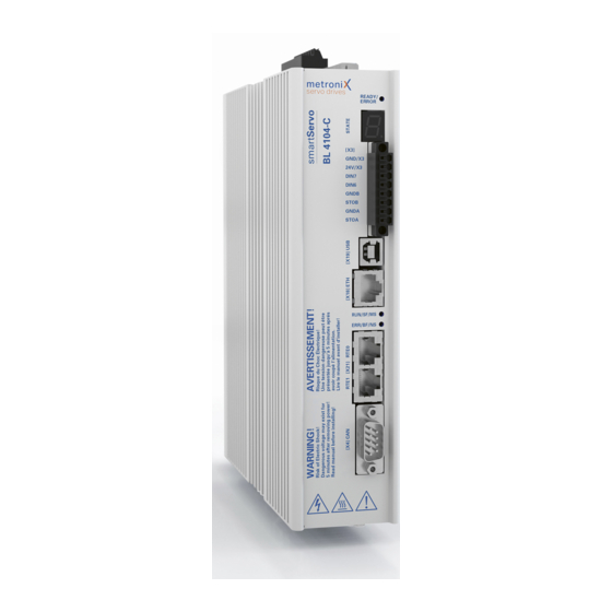
Summary of Contents for Metronix smartServo BL 4000-C Series
Page 1
Product manual BL 4000-C smartServo Important! Read thoroughly before use! Retain for future reference!
Page 2
Metronix does not guarantee that the products meet the buyer’s demands and purposes or that they work together with other products selected by the buyer. Metronix does not assume any liability for damage resulting from the combined use of its products with other products or resulting from improper handling of machines or systems.
Page 3
Contact Metronix Meßgeräte und Elektronik GmbH Kocherstraße 3 38120 Braunschweig Germany Telefon: +49 (0)531 8668 0 Telefax: +49 (0)531 8668 555 E-mail: vertrieb@metronix.de https://www.metronix.de Revision Information Manual title Product manual "BL 4000-C" File name P-HB_BL 4000-C_1p0_EN.pdf Version Year 2019 Product manual BL 4000-C...
Table of Contents Table of Contents 1 About this Product manual 1.1 Explanations and notation 1.1.1 Structure of the warning notes 1.1.2 Notation in this product manual 1.2 Additional documents 1.3 Order numbers 1.4 Applicable standards 2 For your own safety 2.1 General information 2.2 Intended use 2.3 Target group...
Page 5
Table of Contents 4.1.2.2 Communication via Ethernet 4.1.2.3 Changing the communication interface 4.1.2.4 Communication errors 4.1.2.5 Numeric input fields for changing parameters online 4.2 Operating mode and error indication 4.3 Operability check 4.4 Software-guided commissioning 4.4.1 General configuration 4.4.2 Configuration of the display unit 4.4.2.1 Rotatory operation 4.4.2.2 Translatory operation 4.4.2.3 Other setting options...
Page 6
Table of Contents 5.3 Selecting the setpoints 5.3.1 Specifying the setpoints (speed and torque values) 5.3.2 Settings concerning the analogue input AIN 5.3.3 Offset calibration and "Safe zero" 6 Applications 6.1 Homing process 6.1.1 Methods -17 and -18: Stop 6.1.2 Methods -1 and -2: stop with index pulse evaluation 6.1.3 Methods 17 and 18: positive and negative limit switch 6.1.4 Methods 1 and 2: positive and negative limit switch with index pulse evaluation 6.1.5 Methods 23 and 27: reference switch...
Page 7
Table of Contents 6.2.7.1 Linking positions 6.2.7.2 Global settings 6.2.7.3 Digital inputs - Motion program 6.2.8 Jog mode 6.2.9 Setting of digital outputs 6.3 Applications with several angle encoders 6.3.1 Improved position control with two angle encoders 6.3.2 Synchronisation/parameterisation of the master 6.3.3 Synchronisation/parameterisation of the slave 6.3.4 Position-synchronous operation 6.3.5 Special considerations concerning the resolution of the master frequency...
Page 8
Table of Contents 7.2 Oscilloscope 7.2.1 Oscilloscope window 7.2.2 Oscilloscope settings 7.2.2.1 Tabs: CH1 ... CH8 7.2.2.2 Tabs: Time base 7.2.2.3 Tabs: Trigger 7.3 Display units 7.3.1 User-defined display units 7.3.2 Direct input of the display units 7.4 Parameter sets 7.4.1 Online parameterisation: Overview 7.4.2 Loading and saving parameter sets 7.4.3 Offline parameterisation:...
Page 9
Table of Contents 7.6.3.1 Fundamental parameterisation of linear motors 7.6.3.2 Determining the commutation position in the case of linear motors 7.6.3.3 Settings in the homing menu for linear motors 7.6.3.4 Necessary error reactions in the case of linear motors 7.6.4 Manual optimisation of the controllers 7.6.4.1 Motor requirements 7.6.4.2 Reversing generator 7.6.4.3 Manual speed control configuration...
Page 10
8.6.1 Safe torque off (STO) 8.6.2 Deceleration and safe torque switch off(SS1, "Safe Stop 1") 8.7 Prior to commissioning 8.8 Metronix ServoCommander® safety functions 8.8.1 Servo drive type indication and safety function 8.8.2 Status indication of the finite state machine 8.8.3 "Safety module (integrated)" window 8.9 Functional test, validation...
Page 11
Table of Contents 10 Storage/transport 11 Installation 12 Technical data 12.1 General technical data 12.2 Power supply [X9] 12.3 Motor connector [X6] 12.4 Resolver connector [X2A] 12.5 Encoder connector [X2B] 12.6 USB [X19] 12.7 Standard Ethernet [X18] 12.8 Real-time Ethernet [X21] 12.9 CAN bus [X4] 12.10 I/O Interface [X1] 12.10.1 Time response of the digital inputs...
Page 12
Table of Contents 13.4 Connector: motor [X6] 13.5 Connector: resolvers/analogue Hall encoders [X2A] 13.6 Connector: encoder [X2B] 13.7 Connector: USB [X19] 13.8 Connector: standard Ethernet [X18] 13.9 Connector: real-time Ethernet [X21] 13.10 Connector: CAN bus [X4] 13.11 Connector: I/O interface [X1] 13.12 Connector: STO [X3] 14 Maintenance, cleaning, repair and disposal 15 Appendix...
About this Product manual The purpose of this Product manual is to ensure the safe use of the servo drives of the ® BL 4100-C series and of the Metronix ServoCommander parameterisation software (abbreviated "MSC") for servo drives of the BL 4100-C series.
Example: Double-clicking the desired device or clicking the button Establish connection will establish an online connection. Quick-start symbol ® The quick-start symbols in the main window of Metronix ServoCommander are explained as follows: Parameter / IOs / Digital Outputs Additional documents...
1 About this Product manual Applicable standards Standard Description EN 13849-1:2015 Safety of machinery - Safety-related parts of control systems - Part 1: General principles for design EN 50581 Technical documentation for the assessment of electrical and electronic products with respect to the restriction of hazardous substances EN 60204-1 Safety of machinery - Electrical equipment of machines - Part 1:...
2 For your own safety For your own safety General information The BL 4100-C servo drive can only be used safely if you read and comply with this document. The BL 4100-C has a safe design. However, certain hazards exist in the context of certain activities.
2 For your own safety Intended use The electronic drive control unit (servo drive) is intended for operation in combination with electric motors in an industrial environment. The handling of the servo drive requires qualified personnel that have been trained in terms of general and, in particular, electrical safety.
2 For your own safety General safety instructions Danger to life due to electric shock! Non-compliance with the safety instructions will lead to a potentially fatal electric shock. The general set-up and safety rules and regulations concerning the work on power installations (e.g.
2 For your own safety Personal protective equipment Always use personal protective equipment during the transport, installation, start-up, cleaning, maintenance and removal of the servo drive, for example: Protective gloves To prevent superficial hand injuries. ESD safety shoes To prevent foot injuries caused by falling parts. To prevent electrostatic charging.
Page 20
2 For your own safety To prevent accidents, injuries and damage to property: Perform a risk assessment and follow all of the statutory and local safety instructions and accident prevention regulations when installing or maintaining the system. Ensure that the AC or DC power supplies are switched off and locked prior to performing any work in the area of the machine.
2 For your own safety Protection against contact with electrical parts Dangerous electrical voltage! In certain device constellations, the rapid discharge of the DC bus voltage of the servo drive may be rendered ineffective. In these cases, the servo drives may still carry dangerous voltage levels up to 10 minutes after they have been switched off (residual capacitor charge).
2 For your own safety Protection against electric shock by way of protective extra-low voltage (PELV) Dangerous electrical voltage! There is a risk of high electrical voltage due to incorrect electrical connections. Always follow the safety instructions stated hereinbelow. All of the connections and terminals with voltages up to 50 V of the servo drive have protective extra-low voltage.
2 For your own safety safety rules and regulations that apply to the system. Random movements of the machine or other malfunctions may be caused by deactivating, bypassing or failing to activate the safety devices. 2.10 Protection against contact with hot parts Risk of burns due to hot surfaces.
3 Product description Device view Front view Figure 2: Front view 01 Product name 08 LED (RUN/SF/MS) 02 Earthing screw 09 LED (ERR/BF/MS) 03 Status indicator LED 10 [X21] Real-time Ethernet interface (READY, ERROR, ENABLE) 04 Seven-segment status indicator 11 [X4] CANopen interface 05 [X3] STO interface (STOA, STOB), 12 Safety Symbols as per ISO 7000 Limit switch (DIN6, DIN7),...
Page 26
3 Product description Top view / bottom view Figure 3: Top view / Bottom view 14 [X9] Power supply 17 [X2A] Resolver/ analogue Hall sensors 15 [X6] Motor connection 18 Slot for microSD cards 16 [X2B] Multi-encoder 19 [X1] I/O communication Product manual BL 4000-C Page 26 of 298...
All of the servo drives of this series have the following features: Integrated fieldbus interfaces CANopen interface for the integration in automation systems EtherCAT interface (CoE) ProfiNet interface (Metronix standard telegrams, based on PROFIdrive) Integrated universal shaft encoder evaluation for the following encoder types: Resolvers...
Page 28
3 Product description Integrated functional safety "Safe Torque Off (STO)" safety function integrated in the device SS1 functionality possible Homing and positioning Integrated positioning control with a wide range of functions as per "CAN in Automation (CiA) DSP402" plus numerous additional application-specific functions.
Page 29
3 Product description Applications Speed- and angle-synchronous operation with an electronic gear unit via the incremental encoder input or fieldbus. Extensive modes of operation for synchronisation, e.g. "flying saw" Jog mode, teach-in mode, motion programs, torque-limited set control and much more Special control features High control quality due to high-quality sensors, far superior to conventional market...
4 Quick-start guide Quick-start guide This chapter describes the fundamental steps that are necessary for operating a motor with the servo drive for the first time. The correct installation of the servo drive in the control cabinet is described in section 13 Electrical installation on page 235.
Page 31
Ethernet connector). Now, you can communicate with the servo drive by way of the ® Metronix ServoCommander parameterisation software. Risk of injury due to uncontrolled motor movements The DC bus voltage is active. The motor may start although this is not intended.
4.1.1 The user interface ® Figure 4: Main window of Metronix ServoCommander The upper area of the MSC main window includes a menu bar and a toolbar. All of the functions of the program can be activated via the menu bar.
When the program is started, it tries to set up a communication connection to a servo drive via the last interface used. If this fails, the following will be displayed by ® Metronix ServoCommander Figure 5: "Communication interface selection" window Select the interface (USB or Ethernet) via which you would like to parameterise the device.
Ethernet is actually the correct device. When closing the "Communication interface selection" window, some Windows systems ® may freeze the Metronix ServoCommander window for approximately 3 minutes before actually closing it. This is caused by a faulty Windows API function and can be avoided by opening an input prompt and entering the following command: "netsh interface ipv4 set global...
Page 35
4 Quick-start guide Manual assignment of the network address In their delivery state, the servo drives receive their IP addresses automatically. This is realised either via a DHCP server on your network or via Auto-IP if you have set up a 1-to- 1 connection, e.g.
4 Quick-start guide 4.1.2.3 Changing the communication interface If you want to change the communication interface, simply open the Communication interface selection window: Options / Communication Select the desired communication interface and device. 4.1.2.4 Communication errors Cause Measure There are sporadic servo drive 1.
Numeric input fields for changing parameters online Figure 7: Numeric input field for changing parameters online The windows of the Metronix ServoCommander® parameterisation program include fields for numeric inputs. Entries can be made in the following ways: Directly by way of the keyboard: Enter the value directly into the entry line. As long as the entry is not complete, the text will be shown in thin print and will not be transferred to the servo drive yet.
4 Quick-start guide Operating mode and error indication The seven-segment display of the servo drive indicates the operating state and any errors that may be present. Indication Meaning Torque-controlled mode Speed-controlled mode In this mode, the outer segments "rotate". The indication depends on the current position or speed.
4 Quick-start guide Operability check To check whether the servo driver is ready for operation, proceed as follows: 1. Ensure that the STO input is deactivated. 2. Switch on the 24 V power supply. The READY LED on the front panel of the servo drive lights up green.
The commissioning of the servo drive can be performed after the correct installation of the ® Metronix ServoCommander parameterisation program and the setup of a communication connection to the servo drive. In addition, the servo drive should be completely connected and the supply with mains power should be possible.
4 Quick-start guide 4.4.1 General configuration From the outside of the commissioning process, the window can be opened via the menu Parameters/Application parameters/General configuration. Figure 9: "General configuration" window - "General configuration" tab In the Application field, you can choose between a rotatory (indication of values in revolutions, degrees or radian) and translatory application (indication of values in units of length).
Page 42
4 Quick-start guide The checkbox Motor without commutating generator must be ticked for all drives in which the connected angle encoder does not supply any commutation signals, e.g. in the case of linear motors. For a correct commutation of the motor, there must be a valid commutation position after the servo is switched on and before it is enabled for the first time.
Page 43
4 Quick-start guide In the case of the encoders mentioned hereinabove, it is only necessary to adjust the offset angle during the commissioning process. If you do not have a motor with commutation signals, the commutation position must be determined. This will be done whenever the servo drive is started. There are different methods to choose from.
Page 44
4 Quick-start guide Motor overspeed protection The motor overspeed protection function is a mechanism to react to counting errors in the case of pure incremental encoders. The function monitors the drive for "uncontrolled movements". Depending on the operating mode, the motor overspeed protection function is realised by way of different mechanisms: Operating mode Mechanism...
By adapting the display units, physical variables such as the position, speed and ® acceleration can be displayed in the Metronix ServoCommander program as required by your specific application. If you use a linear axis, for example, you can select translatory display units so that the position will be indicated in mm, the speed in mm/s and the acceleration in mm/s².
Enter the maximum speed and acceleration values that you are expecting for your ® application. The Metronix ServoCommander program uses these values for limiting the entries into the program. Any values that are already present in the servo drive will not be limited by this process.
4 Quick-start guide 4.4.4 Configuration of the motor data Parameters/Device parameters/Motor data During the commissioning process, the following menu appears. You can enter the maximum and nominal current values of the motor into this menu. Figure 12: "Motor data" window Enter the current values based on the data on the type plate.
Page 48
4 Quick-start guide The maximum current limits may depend on the clock frequency of the output stage. To parameterise the clock frequency, click the Power stage button. I²t time is the time interval in which the I²t value increases to 100%. The I²t value describes the current load of the motor.
4 Quick-start guide 4.4.5 Safety parameters This menu is used to parameterise the limitations and monitoring functions of the drive. They are not functions in the sense of functional safety. Fields that are irrelevant for the commissioning process are greyed out. Outside of the commissioning process, the menu can be activated via Parameters/Safety parameters.
Page 50
4 Quick-start guide Encoder difference monitoring: This option is useful if the encoder used for determining the actual position is a different encoder than the one that is used for determining the commutation position/actual speed. The parameter Actual position value - commutation position can be used to define an interval in which both positions may differ from one another.
Page 51
4 Quick-start guide Shutdown level of following error can deactivate the drive if the set and actual position differ from one another by an amount that is greater than the set threshold value. The reaction must be parameterised accordingly in the error management system (see section 9.1 Error management on page 210).
4 Quick-start guide 4.4.6 Motor temperature monitoring This menu is used to configure the motor temperature monitoring function. The menu can also be opened via Parameters/Device parameters/Temperature monitoring. Figure 14: "Temperature monitoring" window It is possible to directly select typical sensors for the analogue motor temperature sensor. In addition, non-linear characteristic curves with up to 10 interpolation points can be parameterised.
4 Quick-start guide 4.4.7 Commutation encoder This menu is used to define the input through which the servo drive will receive its commutation information. The menu can also be opened via Parameters/Device parameters/Actual value selection. State the connection through which the commutation information and the actual speed value will be provided.
4 Quick-start guide 4.4.8 Angle encoder settings Parameters/Device parameters/Angle encoder settings/X2B The menu is skipped during the commissioning process, if a resolver (X2A) is used as the commutation encoder. If the commutation encoder is connected to X2B, additional information about the angle encoder must be provided.
4 Quick-start guide 4.4.9 Angle encoder identification (automatic determination) The angle encoder is automatically identified during the commissioning process. The following parameters are determined during the identification: Number of pairs of poles Angle encoder offset Phase sequence of the angle encoder (anti-clockwise, clockwise) Outside of the commissioning process, the function can be accessed via the following menus: Parameters/Device parameters/Motor...
4 Quick-start guide 4.4.10 Automatic identification of the current controller Damage to property caused by incorrect data Incorrect data of the current controller gain and time constant may cause oscillations. This, in turn, may destroy the motor and the servo drive. The current controller is automatically identified during the commissioning process.
Configuration of the speed controller (auto-tuning with FAST) ® The Metronix ServoCommander parameterisation program and the auto-tuning tool FAST (Flexible Advanced Servodrive Tuning) can be used for the automatic determination of the parameters for the speed and position controller with regard to the application.
Page 58
4 Quick-start guide Figure 18: "Auto tuning" window For the system identification, it is important to enter the values of a possibly existing gear. Then, the controller dimensioning can be selected, and the identification process of the auto-tuning tool FAST can be started by way of the button System identification with controller dimensioning.
4 Quick-start guide 4.4.13 Configuration of the position controller If the automatic identification (FAST) has not been successful, the system suggests using the default parameters for the position controller. Figure 20: "Position controller" window If the automatic identification of the controller parameters has not led to an optimum result, the drive can be optimised manually.
Page 60
4 Quick-start guide In addition, the following settings can be made in the "Position controller" window (please note that they are not shown during the commissioning process). Following error: Message: Parameterisation of a positive and negative following error and of a response delay.
4 Quick-start guide 4.4.14 Permanent storage of the parameters File/Parameter set/Save parameter set (EEPROM) For a successful completion of the parameterisation, the parameters must be stored permanently in the servo drive. Click Next >>. Figure 21: "First commissioning" window Saving the data in a DCO file The values determined during the commissioning process should be saved permanently in the servo drive and also in a file on the PC.
5 Enabling the servo drive and selecting the set values Enabling the servo drive and selecting the set values After the commissioning process, the servo drive can be enabled, and the motor can perform a movement. Configuring the enable logic In order to be able to enable the servo drive, the enable logic must be configured.
Page 63
5 Enabling the servo drive and selecting the set values After the servo drive has been successfully enabled, the following conditions must be fulfilled: No errors DC bus charged Encoder systems completely initialised (it may take some time to read the parameter sets out of the encoder) STO inactive (X3 correctly connected and emergency cut-out deactivated) Damage to the system due to unwanted movements...
Page 64
5 Enabling the servo drive and selecting the set values The STO inputs must be connected to the 24 V supply so that the drive can be enabled by clicking Controller enable. If you click again, the drive will be disabled. Figure 23: "Commands"...
5 Enabling the servo drive and selecting the set values Operating modes The operating mode can be changed in the "Commands" window. This window is permanently displayed. To change the operating mode, select the corresponding button. However, this should not be done when the servo drive is enabled. The various operating modes are described in detail in the next chapters.
5 Enabling the servo drive and selecting the set values 5.2.2 Speed-controlled mode (speed control) In speed-controlled mode, a specific speed setpoint is specified. The servo drive determines the actual speed n_actual by evaluating the encoder data. To ensure compliance with the speed setpoint, the current setpoint i_set is determined.
5 Enabling the servo drive and selecting the set values 5.2.3 Position-controlled mode and positioning mode (positioning process) In position-controlled mode/positioning mode, a superordinate position controller is active in addition to the speed control. This position controller processes the deviation of the actual position from the set position and converts it into the corresponding set values for the speed controller.
5 Enabling the servo drive and selecting the set values 5.2.4 Using the servo drive in jog mode Parameters/Positioning/Go to destination Figure 26: "Go to destination" window If the servo drive is in Positioning mode, the drive can be moved manually by clicking and holding the arrow buttons.
5 Enabling the servo drive and selecting the set values Selecting the setpoints Operating mode/Setpoint selectors In the operating modes Torque control Speed control, the setpoint source can be selected. Figure 27: "Setpoint selectors" windows - "Speed control" tab The following setpoint sources can be selected: Analog input Fixed value 1 (this is also used by fieldbus systems and can be labelled accordingly: CANopen/EtherCAT/PROFINET, etc.) (the setting depends on the...
5 Enabling the servo drive and selecting the set values 5.3.1 Specifying the setpoints (speed and torque values) In the Setpoint selectors window in Selector A Fixed value 1, click "..." to specify the setpoints. You can also access the menu via Operating mode/Setpoint value (speed).
5 Enabling the servo drive and selecting the set values 5.3.2 Settings concerning the analogue input AIN Parameters/IOs/Analogue inputs or in the Setpoint selectors window by way of the button “...“ Figure 29: "Analogue inputs" window The values that need to be set are used to specify the "conversion factor" for the conversion between the input voltage and setpoint.
5 Enabling the servo drive and selecting the set values 5.3.3 Offset calibration and "Safe zero" In some cases, an external voltage of 0 V may still generate a very small setpoint because the upstream electronic system and the analogue input path have an offset. In this case, the offset can be calibrated.
® A homing run can be started via a fieldbus, Metronix ServoCommander or a digital input. It can also be performed automatically when the servo drive is enabled. For homing, several different methods have been implemented following the DSP 402 CANopen protocol.
6 Applications 6.1.1 Methods -17 and -18: Stop If this method is used, the drive moves in the positive direction (-18) or negative direction (-17) until it reaches the stop. Normally, a 50% increase of the i²t value is used as the criterion for detecting the stop.
6 Applications 6.1.3 Methods 17 and 18: positive and negative limit switch If these methods are used, the drive moves in the positive direction (18) or negative direction (17) at search speed until it reaches the limit switch. Then, the drive moves back at crawl speed and tries to find the exact position of the limit switch.
6 Applications 6.1.5 Methods 23 and 27: reference switch These two methods use a reference switch which is active only over a certain part of the distance. This method is particularly suitable for rotary axis applications in which the reference switch is activated once during every rotation. If this method is used, the drive moves in the positive direction (23) or negative direction (27) at search speed until it reaches the reference switch.
6 Applications 6.1.6 Methods 7 and 11: reference switch and index pulse evaluation Like methods 23 and 27, methods 7 and 11 use the reference switch. In addition, however, the home position refers to the first index pulse in the negative or positive direction as seen from the reference switch.
6 Applications 6.1.7 Methods -23 and -27: homing run (positive/negative) to the reference switch These methods are similar to the methods 23 and 27. However, in this case, the system tries to locate the end of the range of movement, e.g. the stop or a limit switch, in a first step.
6 Applications 6.1.9 Method 34: homing to the current position In the case of method 34, the home position refers to the current position, i.e. the current position of the drive is set to zero. 6.1.10 Parameterisation of the homing method Parameters/Positioning/Homing position The homing run can be parameterised in the Homing position...
6 Applications 6.1.11 Parameterisation of the homing run: settings Under the Settings tab, a window opens where the following settings can be made: Figure 41: "Homing position" window - "Settings" tab Homing after reset and controller enable If this option is selected, the homing run will not be started until the servo drive is enabled for the first time after the 24 V supply has been activated.
Page 81
6 Applications detect any target signals (e.g. a limit switch) or the home position within this search distance, it will issue an error message. Max. position limits If this button is clicked, the search distance will be determined based on the maximum position limits.
6 Applications 6.1.12 Parameterisation of the homing run: motion profile Figure 42: "Homing position" window - "Driving profile" tab Here, you can enter speed and acceleration values as well as jerk-free parameters for the following processes: Search Movement of the drive until it reaches the target (limit switch, reference switch, stop) Crawl Reversal of the movement (at low speed) to determine the contact threshold...
6 Applications 6.1.13 Tab: Index pulse control Index pulse control (index pulse monitoring) is important if a target other than "index pulse" has been selected and the reference point is an "index pulse". If the target is located very close to the index pulse, slight changes in the mechanical system may cause a point slightly "before"...
6 Applications 6.1.14 Tab: Torques The conventional homing method based on a stop can be optionally refined by way of a homing run to a comparison torque. As a result, the target of the homing run is reached when the specified comparison torque is reached. In this case, the system no longer uses the criterion "50% increase of the i²t value".
6 Applications 6.1.15 Tab: Special functions The checkbox Flying referencing activates a function that is similar to a homing run. Figure 45: "Homing position" window - "Special functions" tab The "flying referencing" function can be used to avoid accumulating errors in endless applications.
6 Applications Positioning process The servo drive has a table of 256 positions which can be used for the advance parameterisation of target positions. In addition, there are special position sets for the fieldbus and jog mode. 6.2.1 Global positioning settings For applications in the position-controlled mode and in positioning mode, certain fundamental parameters must be configured.
6 Applications 6.2.2 Destination parameters: general buttons Parameters/Positioning/Destination parameters Figure 47: "Destination parameters" window - "Settings" tab The button Positioning settings can be used to change the general positioning settings (e.g. the position limits) (see section 6.2.1 Global positioning settings on page 86). The button can be used to start a positioning run with the position set that is currently displayed.
6 Applications 6.2.3 Destination parameters: Settings tab Parameters/Positioning/Destination parameters The target positions are parameterised in the menu stated hereinabove. The window below will be displayed. It includes the tab Settings: Figure 49: "Destination parameters" window - "Settings" tab You can select the target position to be parameterised in the field on the left. The field Start during positioning run defines the behaviour of the servo drive if the start...
Page 89
6 Applications Bouncing switches Please note that a bouncing switch at the digital start input may cause problems if Immediately go to new target is permitted during a relative positioning run. The drive may move just a little too far! The input field Start delay is used to define a time interval that passes after the start...
6 Applications 6.2.4 Destination parameters: Driving profile tab Parameters/Positioning/Destination parameters Figure 50: "Destination parameters" window - "Driving profile" tab You can enter the target position into the field Destination. You can state whether the specified target should be interpreted as an absolute value (referred to the reference point) or as a relative value.
Page 91
6 Applications The illustration below shows a motion profile with 2 sets (P1 and P2). In the picture on the left, the drive decelerates to zero before the second positioning run is started. In the picture on the right, the final speed of the first set has been set to the profile speed v the second set.
6 Applications 6.2.5 Destination parameters: Experts tab Parameters/Positioning/Destination parameters Figure 52: "Destination parameters" window - "Experts" tab The list Destination is acquired... can be used to specify the source of the target position for the current positioning run: From the positioning set This is the default setting.
Page 93
6 Applications automatically based on the current position, target position and any additional options (absolute, relative, relative to last destination etc.). Priority of the options The option SW-limit switch as target position is usually used only for position sets in the jog mode.
Page 94
6 Applications synchronisation process. The current master position is stored by the master frequency input whenever a trigger event occurs. A new synchronisation process requires a new start command. The target will be calculated based on the stored synchronous position. The advantage of this method is the higher level of precision when the synchronous target is determined as jitter during the start of the synchronisation process is reduced.
There are different ways to select target positions and to start the associated positioning runs: via digital inputs ® via the parameterisation interface (Metronix ServoCommander via a fieldbus (described in the respective fieldbus manual) 6.2.6.1 Positioning via digital inputs The individual targets are selected via the digital inputs. A rising edge of the digital input that has been parameterised for the start of a positioning run leads to the adoption of the target and the start of the positioning run.
Page 96
6 Applications The movement to the target position and the homing run can be started by way of ® Metronix ServoCommander Figure 53: "Go to destination" window Go to destination Destination 0 to 15: Click the button to move to the associated position.
6 Applications 6.2.7 Motion program A motion program can be used to link several position sets to form a sequence. These positions will be approached one after the other. Based on its motion program options, a position set can become part of a motion program. The result is a linked list of positions: Figure 54: Motion program Features:...
6 Applications 6.2.7.1 Linking positions Parameters/Positioning/Destination parameters The following window is displayed under the Course program (motion program) tab: Figure 55: "Destination parameters" window - "Course program" tab In the area Following position, the positions can be linked. Up to two following positions can be specified (field Following position 1 Following position...
Page 99
6 Applications The area Reaction concerning NEXT1/NEXT2 signal can be used to specify if and under which condition positions will be approached. This will be explained based on the example in Figure 54 (Motion program). Pos. Task Parameterisation If NEXT1 = 1, move to pos. 3 immediately. Following position: Following position 1 If NEXT2 = 1, move to pos.
6 Applications 6.2.7.2 Global settings The global settings for the motion program are made in the menu Parameters/Positioning/Global positioning settings. See also section 6.2.1 Global positioning settings on page 86. The window includes the following area which is relevant for the motion program: Figure 56: "Global positioning settings (course program)"...
6 Applications 6.2.7.3 Digital inputs - Motion program Parameters/IOs/Digital inputs The following assignments can be defined via the Course program (motion program) tab: Figure 57: "Digital inputs" window - "Course program" tab The fields HOME START can be used to define the two digital inputs that trigger the entry into the motion program.
6 Applications 6.2.8 Jog mode Jogging is the controlled movement of a drive to a specific position. The drive continues to move as long as a specific input signal is active. The servo drive supports jogging in a positive and negative direction. A separate speed of movement and separate acceleration values can be specified for every direction.
6 Applications 6.2.9 Setting of digital outputs Parameters/IOs/Digital outputs The setting of digital outputs in the positioning mode can be used to inform a superordinate control system that a positioning run has been, or is being, completed: Option 1 Position setpoint = target position Option 2 Actual position = target position Option 3...
6 Applications Applications with several angle encoders So far, only applications with a single angle encoder have been discussed. The angle encoder provides information about the commutation position and about the actual speed and position. The individual pieces of information can also be provided by more than one encoder.
6 Applications 6.3.1 Improved position control with two angle encoders When a second encoder is used at the output, the control of a target position can be improved. At the same time, the servo drive can be synchronised with an external synchronisation source via an additional input (3-encoder operation).
6 Applications The adaptation to the desired system of units can then be realised by way of the display units. It is important to select appropriate combinations. Typical configurations of two encoders (drive/output): Resolver/incremental encoder Resolver/analogue SINCOS encoder Resolver/serial encoder EnDat, Hiperface encoder/incremental encoder X1 If a serial encoder with a parameter set (EnDat/Hiperface) is used at the output, the commutation data of the encoder parameter set will be suppressed when the firmware is...
6 Applications 6.3.4 Position-synchronous operation The BL 4100-C servo drives can be used in a master-slave configuration, hereinafter referred to as "synchronisation". The servo drives can be a master or a slave. If the servo drive is the master, it can provide the slave with its current rotor position via the incremental encoder output.
6 Applications Flying saw Risk of injury due to unexpected automatic starting Unexpected automatic starting may occur if the synchronisation process is started due to an external event. Ensure that all of the drives are switched off before any person accesses the danger area.
6 Applications 6.4.1 Conventional synchronisation An external setpoint position can be specified for the servo drive via the master frequency input. This position will be converted by way of a certain factor (electronic transmission) in the synchronisation unit. In the Synchronised mode (command window), this setpoint is directly supplied.
6 Applications 6.4.2 Parameterisation and configuration After the I/Os have been wired in a suitable manner for the sampling process and the start of the positioning process, a range of parameters must be configured in various menus to realise the "flying saw" function: The synchronous position information is supplied to the servo drive by way of incremental encoder pulses (either by the servo drive that drives the conveyor belt or by another encoder that is installed on the conveyor belt).
6 Applications 6.4.3 Synchronisation activation and deactivation (example) The following example describes how the function "Gripping of moving objects on a conveyor belt" can be realised. It is assumed that the objects move on a conveyor belt with the variable speed V .
6 Applications 6.4.5 Gripping of the object/position set 1 When the object reaches the light barrier, the gripper must move with the same speed as the conveyor belt. In addition, it must position itself precisely above the object. sync Consequently, P1 results from the position of the light barrier minus half of the width of the object.
6 Applications 6.4.6 Depositing of the object/position set 2 The gripper must now deposit the object on the pallet. The precise starting position of this positioning process is not known. This is why the gripper must move to the pallet based on an absolute target position.
6 Applications 6.4.8 Wiring To ensure the optimum precision of the synchronisation process, the signal of the light barrier must be supplied to the start/sample input without delay or jitter. During the synchronisation process, any delay or jitter will lead to a position deviation based on the following relationship: If the light barrier has a jitter of ±5 ms, for example, a position deviation of ±90°...
6 Applications 6.4.12 Triggering the starting process based on several sources When connecting the light barrier, it must be ensured that the delay times are as short as possible. A connection through a PLC does not make any sense in many cases (high speed, high positioning requirements).
6 Applications 6.4.15 Summary The checkbox Synchronised of the position set is used for the "flying saw" function. When Flying saw mode is active in the command window, the synchronisation can be activated or deactivated by starting a position set. If the synchronisation is active, the position of the encoder (master) that has been selected for the synchronisation is added to the position setpoint.
6 Applications Rotary axis mode Parameters/Application parameters/Rotary axis This menu is used for the configuration of rotary axis applications. They are used, for example, for indexing rotary tables. In the case of a rotary axis application, the actual position is artificially limited to a certain interval. If the actual position exceeds the limit of the interval on the right-hand side, it assumes the limit value for the left-hand side and vice versa.
Page 118
6 Applications Figure 69: Rotary motion in the rotary axis mode The options can be selected for the Mode of the rotary axis: Inactive: The rotary axis is not active. The actual position will not be limited. Active: The rotary axis is active. The synchronous position will be limited. Apart from the activation, the way the servo drive performs the positioning process can also be specified for the standard rotary axis: Shortest...
7 Additional settings Additional settings This chapter provides extensive information about additional settings for adapting the servo drive perfectly to your application, e.g.: Configuration of digital inputs and outputs Adaptation to different types of angle encoders Brake control ® Bluetooth communication Figure 70: "Bluetooth: Configuration (servo drive)"...
7 Additional settings Oscilloscope Display/Oscilloscope The oscilloscope function of the parameterisation program can be used to display the development of signals as well as the digital states of the servo drive. There are two windows: the actual oscilloscope and the window for configuring the oscilloscope. 7.2.1 Oscilloscope window Figure 71: "Oscilloscope"...
Page 121
7 Additional settings Meaning Symbol Saves the oscilloscope window as a bitmap file. Maximises the oscilloscope window. Minimises the oscilloscope window. Displays the signal curves as a thick/thin line. Opens the settings window. Defines/indicates whether the oscilloscope is activated or deactivated.
7 Additional settings 7.2.2 Oscilloscope settings The "Oscilloscope settings" window includes several tabs for precise settings. CH1…CH8: selection of the measured quantity of channel 1...4 (can be extended to 8) Time base: setting of the time base Trigger: configuration of the trigger Options: for example, for saving the oscilloscope settings The tabs will be explained in detail in the following sections.
Page 123
7 Additional settings Offset This field is used for shifting the curve in the vertical direction. Click the button to reset the offset to zero. AC-coupling Select this option to display the signal without its mean value. This means, for example, that a sinusoidal voltage with a DC offset would be displayed around the neutral line regardless of the DC component.
7 Additional settings 7.2.2.2 Tabs: Time base Figure 73: "Oscilloscope" window - "Time base" Tab The upper Time slide can be used to define the time resolution. A value of 10 ms/div, for example, means that the width of one square of the oscilloscope display corresponds to 10 ms.
7 Additional settings 7.2.2.3 Tabs: Trigger The drop-down list Trigger source can be used to specify the channel that will be used for starting ("triggering") the oscilloscope recording process. Figure 74: "Oscilloscope" window - "Trigger" Tab A distinction is made between digital and analogue trigger sources. Digital trigger sources can only have the state yes or no (active or inactive).
Direct input. ® Display units: representation in Metronix ServoCommander ® The display units only affect the representation in Metronix ServoCommander . They have no effect on the scaling of data that are transferred via a fieldbus (e.g. CANopen Factor Group). 7.3.1 User-defined display units All user-defined units (User-defined) are displayed with [..].
Direct input under Options/Display units. Figure 76: "Display units (direct input)" window ® In addition, you can select the following display units for the Metronix ServoCommander parameterisation program: Increments Degree Radian Revolution Metre...
® Figure 77: Parameter set management with Metronix ServoCommander The current parameter set of the servo drive is stored in the RAM. The RAM will be erased when the power supply is switched off. To save the parameter set in a non-volatile manner, it can be copied into the EEPROM (flash) by clicking the symbol shown above or by selecting the corresponding menu item.
Parameter files on the PC have the extension DCO. This is why parameter files are often referred to as DCO files. DCO files can be read or ® saved in Metronix ServoCommander as follows: Reading a DCO file...
7.4.3 Offline parameterisation: The illustration below shows the offline parameterisation principle: ® Figure 78: Offline parameterisation with Metronix ServoCommander Displaying the parameterisation Usually, the offline parameterisation function is used for displaying the parameters of DCO files. The modification of parameters is useful only in individual, specific cases since stability and functionality tests are not possible by simply loading a parameter set into the servo drive.
7 Additional settings 7.4.4 Parameterisation via a microSD card The BL 4100-C servo drive has a card slot for microSD cards. It can be used for loading and saving parameter sets. The process can be started explicitly via the parameterisation program or automatically after a restart of the servo drive (reset or power on).
Page 132
7 Additional settings Options This is where you can configure the behaviour when DCO file is loaded from the SD card. Loading a DCO file The selected settings are stored in the parameter set. When a DCO file is loaded, the current settings of the servo drive will be overwritten.
Page 133
7 Additional settings Conditional loading of data from the SD card (autorun.ini) An AUTORUN.INI file on the microSD card can be used to define specific conditions for loading DCO files. You can specify, for example, that only the fundamental parameters, certain position sets or complete parameter sets will be loaded into the servo drive.
7 Additional settings Angle encoder settings Parameters/Device parameters/Angle encoder/Settings... This section provides details about the various options of the encoder interface. It describes the manual configuration of the angle encoders connected to X1, X2A and X2B/X6. 7.5.1 "Commutating-generator" tab Figure 80: "Angle encoder settings" window - "Commutating-generator" tab Offset of encoder is the angle difference between the electrical and mechanical position that results from the installation position of the angle encoder on the motor shaft.
7 Additional settings 7.5.2 "X2A" tab Figure 81: "Angle encoder settings" window - "X2A" tab This tab is used for the parameterisation of an angle encoder connected to X2A. This can either be a resolver or an encoder with analogue Hall sensors. Single- and multi-pole resolvers are supported.
7 Additional settings 7.5.3 "X2B/X6" tab Figure 82: "Angle encoder settings" window - "X2B/X6" tab - "Encoder list" Different types of encoders can be connected to X2B (see also section 12.5 Encoder connector [X2B] on page 220): Digital incremental encoders (RS422, HALL sensors) Analogue incremental encoders (1 V Incremental encoders with a serial interface (RS485 level, e.g.
7 Additional settings 7.5.3.1 General settings Figure 83: "Angle encoder settings" window - "X2B/X6" tab - "Settings" The following settings are available for all types of encoders: Encoder type This setting is used to define the encoder type. The encoder types and their parameters are described in detail in the following sections.
Page 138
7 Additional settings Line count At a constant speed, incremental encoders provide two periodic signals with a phase shift of 90° between them (A/B track or Z0 track). The line count corresponds to the number of full periods per revolution. In most cases, the line count is stated on a data sheet or type plate of the angle encoder.
7 Additional settings 7.5.3.2 Digital incremental encoders Figure 84: "Angle encoder settings" window - "X2B/X6" tab - "Settings" - "Encoder type: Digital" Encoder type Select Digital if you want to use a digital incremental encoder. Options Encoder with AB track The AB track provides incremental (square) track signals.
Page 140
7 Additional settings Encoder with Hall signals Hall signals can be used for an initial determination of the commutation position if a digital incremental encoder is used. Following a reset, the commutation position can be determined with an accuracy of 30° using the Hall signals. This is sufficient for a starting process.
7 Additional settings 7.5.3.3 Analogue incremental encoders Figure 85: "Angle encoder settings" window - "X2B/X6" tab - "Settings" - "Encoder type: Analogue" Encoder type Select Analogue if you want to use an analogue incremental encoder. Options Encoder with Z0 track The Z0 track (according to the Heidenhain terminology) is a term used for the actual, high-resolution analogue track signals.
Page 142
7 Additional settings Encoders with reference pulse The reference pulse of an analogue incremental encoder corresponds to the index pulse of a digital incremental encoder. Information as to whether the angle encoder has such a pulse can be found on the data sheet of the angle encoder. Risk of injury due to uncontrolled drive movements.
7 Additional settings 7.5.3.4 Serial: EnDat 2.2 Heidenhain encoders with an EnDat 2.2 interface have a serial communication channel via which the servo drive can communicate with the encoder. This channel is used for the purely digital transfer of the position value from the encoder. In addition, it is possible to access the type plate of the encoder to read out certain characteristics such as the line count, for example.
7 Additional settings 7.5.3.5 Serial: HIPERFACE Sick-Stegmann encoders with a Hiperface interface have a serial communication channel via which the servo drive can communicate with the encoder. It is used, for example, to determine the commutation position. In addition, it is possible to access the type plate of the encoder to read out certain characteristics such as the line count, for example.
7 Additional settings 7.5.3.6 Serial: HIPERFACE DSL Sick-Stegmann encoders with a Hiperface DSL interface have a serial communication channel via which the servo drive can communicate with the encoder. In the case of Hiperface DSL, data are transferred via conductors that are integrated in the motor cable. As a result, a separate encoder cable is not required.
7 Additional settings 7.5.3.7 Serial: BiSS The BiSS interface is a non-proprietary, serial real-time interface. The support of BiSS encoders includes the following functions: Support of BiSS C Support of typical encoders made by Hengstler, Kübler and Balluff Mapping of a BiSS absolute encoder to variable pole lengths of a linear motor Support of frame lengths with absolute position information of 32 bits maximum in a 40-bit frame Generator polynomial 0x43 (6 bits)
Page 147
7 Additional settings To adapt the BiSS position taken from the digital raw value of the encoder to the internal absolute position and rotor position, the following variants can be used: Relative-linear: The BiSS data are available only as a data frame without any connection with regard to the rotor position.
7 Additional settings 7.5.3.8 Storing parameters in the encoder If the angle encoder connected to X2B has an EEPROM, the parameters can be stored in the encoder. This is particularly useful for parameters that refer to the characteristics of the motor (nominal and maximum current) or to the motor/encoder combination (phase sequence, offset angle).
Page 149
7 Additional settings Parameter set exists This LED indicates that an encoder parameter set is stored in the EEPROM of the connected encoder. However, this parameter set may not be loaded. Parameter set loaded This LED indicates that the encoder parameter set has been loaded and that the corresponding settings of the internal parameter set of the servo drive have been overwritten.
Page 150
7 Additional settings To avoid this situation, we recommend the following: 1. Disconnect the encoder connector. 2. Perform a reset. The encoder parameter set cannot be loaded, and the parameters of the servo drive will not be overwritten. 3. Deactivate the option Load parameter set from encoder EEPROM after reset.
7 Additional settings 7.5.4 "X1" tab Parameters/Device parameters/Angle encoder/Settings... Figure 91: "Angle encoder settings" window - "X1" tab Here, you can specify whether the inputs at connector X1 will be used as the master frequency input or output. If "Input" is selected, you can either connect the master frequency output of another BL 4100-C servo drive or an incremental encoder (quadrature evaluation).
Page 152
7 Additional settings Line count Digital incremental encoders supply their angular information with the aid of track signals. They supply periodic square (digital) signals at constant speed. The line count corresponds to the number of full periods of a track per revolution. In most cases, the line count is stated on a data sheet or type plate of the angle encoder.
7 Additional settings Parameterisation of the motor and output stage 7.6.1 Methods for analysing motor problems In most cases, motor problems are indicated by noise and poor concentricity. In a first step, the internal oscilloscope should be used to analyse the current ripple, for example at 100 rpm.
7 Additional settings 7.6.2 Configuration of the output stage This menu (Parameters/Device parameters/Power stage) can be used to configure the settings for the PWM generation by the output stage. The option Enhanced sine commutation enables a better utilisation of the DC bus voltage and, consequently, approx.
Figure 92: "General configuration" window In order to obtain a translatory representation of the values in the ® Metronix ServoCommander parameterisation program, open the window Parameters/Application parameters/General configuration and select the option translatory motion and tick the checkbox Linear motor.
Page 156
7 Additional settings Configuration: Parameters/Device parameters/Motor data Motor i²t time: The value can be found on the data sheet of the motor. Number of pole pairs: In the case of linear motors, this value must be set to 1. All the other settings always refer to this value (e.g.
Page 157
7 Additional settings Configuration of the angle encoder settings: Parameters/Device parameters/Angle encoder/Settings... X2B / X6 tab Active angle encoder setting concerning X2B/X6 The setting must be adopted by way of "SAVE+RESET". The button will be displayed in the menu window. Configuration of the line count: The line count must be calculated based on the pole length.
7 Additional settings 7.6.3.2 Determining the commutation position in the case of linear motors In the case of linear motors with angle encoders without commutation signals, the method for the automatic determination of the commutation position must be applied. This can be specified in the window Parameters/Application parameters/General configuration on the...
Page 159
7 Additional settings Mode Mode is mainly determined by the design and layout of the motor. Three different modes are available: Self-adjustment method: With this method, the drive moves over the double search range in a controlled manner. Depending on the initial position, the drive may jerk. This method is not suitable for vertical applications.
7 Additional settings 7.6.3.3 Settings in the homing menu for linear motors After the commutation position of a motor without a commutation encoder has been determined, the configured homing run will be started automatically. This is necessary, as the system lacks reference with regard to the mechanical system of coordinates. When a motor without a commutation encoder is started for the first time, it is possible to read in a reference pulse via the index pulse track at connector X2B (see below).
7 Additional settings 7.6.3.4 Necessary error reactions in the case of linear motors The window Error/Error management can be used to define the reactions of the servo drive to various operating states. In the case of linear motors, a particularly "sharp" reaction must be parameterised for some events: The following error settings must be realised or verified prior to using the linear motor for the first time:...
7 Additional settings 7.6.4 Manual optimisation of the controllers 7.6.4.1 Motor requirements A servo drive used for controlling a motor consists of a DC bus that is supplied by way of the mains power supply (via a rectifier). The DC bus, in turn, supplies an inverter. This inverter uses switching transistors (e.g.
Page 163
IGBTs that are used. Servo drives made by Metronix enable a variable adjustment of the clock frequency in the current controller circuit. In most cases, the clock frequency can be configured by way of ®...
7 Additional settings 7.6.4.2 Reversing generator Display/Reversing generator Figure 95: "Reversing generator" window The reversing generator can be used to initiate a cycling positioning process to optimise the drive. The distance for the reversing movement (Reversing distance), the Speed the acceleration values (Acceleration, Deceleration) can all be parameterised. Use the button GO!/STOP to start and stop the movement.
Page 165
7 Additional settings Adjust the speed controller so that only a small overshoot of the actual speed value occurs. The overshoot should be approx. 15% higher than the speed setpoint. This setting applies to most motors that can be operated with the servo drive. If an even "harder" control response is required, the gain of the speed controller can be increased even further.
Page 166
7 Additional settings Open the Speed controller menu (Parameters/Controller parameters/Speed controller) and optimise the control parameters. Save the settings by way of File/Parameter set/Save parameter set. After the numbers have been changed, there may be two different situations: If the setting is too hard, the speed controller will become unstable (diagram on the right).
7 Additional settings Digital encoders with a low line count as well as resolvers require a high time constant as, otherwise, the quantisation of the actual speed value will be too rough and bit noise can be heard if the gain of the speed controller is high. Time constant An excessive time constant in the speed filter leads to decreased stiffness.
7 Additional settings Digital inputs Hazards for the user The digital inputs of the servo drive are not suitable for safety-oriented applications. Nine digital inputs provide fundamental control functions (see section 12.10 I/O Interface [X1] on page 224). The BL 4100-C servo drives have a target table in which the positioning targets can be stored and from which they can be retrieved at a later point of time.
7 Additional settings 7.7.1 Configuration of the digital inputs Parameters/IOs/Digital inputs The servo drives have numerous functions that can be triggered via the digital inputs. Some of these functions are assigned to special digital inputs in a fixed manner. The other functions can be assigned to the other digital inputs as required by the specific application.
Page 170
7 Additional settings Sample input The sample input can be used for saving the current position in the internal memory so that it can be used for calculations (e.g. for length measurements or for increasing the resolution for flying saw applications). Homing process For homing, the start signal and the reference switches can be actuated by way of digital inputs.
Page 171
7 Additional settings Digital input Affects See section Position selector Positioning 6.2.8 Jog mode Page 1 process Start Positioning Positioning process Page 86 process Sample input Positioning Flying saw Page 108 process Digital stop Speed control 5.2.2 Speed-controlled mode (speed Page 66 process control)
7 Additional settings Digital outputs Hazards for the user The digital outputs of the servo drive are not suitable for safety-oriented applications. There are three digital outputs available for displaying the operating states of the servo drive. The menu Display/Digital outputs provides an overview of the available digital outputs and their current function assignment.
7 Additional settings 7.8.1 Configuration of the digital outputs Parameters/IOs/Digital outputs The following functions can be assigned to a digital output: Digital output See section I²t monitoring active 4.4.4 Configuration of the motor data Page 47 Comparison speed 7.8.2.2 Speed message window: "Comparison Page 175 speed reached"...
7 Additional settings 7.8.2 Configuration of the messages for the digital outputs Under the menu Parameters/Signals, a window appears in which the speed messages, target position messages and following error messages can be parameterised. 7.8.2.1 Torque message window: "Comparison torque" The tab Comparison torque offers the following setting options:...
7 Additional settings 7.8.2.2 Speed message window: "Comparison speed reached" The tab Speed signal offers the following setting options: Figure 101: "Signals" window - "Speed signal" tab The parameters Comparison speed, Signal window Response delaycan be used to control the function Speed reached of a digital output.
7 Additional settings 7.8.2.3 Target position message window: "X = X " actual target The tab Destination (target position) offers the following setting options: Figure 102: "Signals" window - "Destination" tab These parameters can be used to control the function X of a digital output.
7 Additional settings 7.8.2.4 Following error message window: "Following error" The tab Following error offers the following setting options: Figure 104: "Signals" window - "Following error" tab These parameters can be used to control the "following error" function of a digital output. Figure 105: "Following error"...
7 Additional settings Position triggers The menu can be found under Parameters/I/Os/Position trigger. The position triggers can be used to transfer information concerning the logic states of the position triggers and rotor position triggers to the digital outputs. 4 position triggers can be configured (vertical lines).
Page 179
7 Additional settings Combining triggers by way of an OR function Please note that the combination by way of an OR function can only be performed for one group.Using an OR function for position triggers and rotor position triggers, for example, is not possible.
7 Additional settings 7.9.1 Position triggers The menu can be found under Parameters/I/Os/Position trigger - Parameters. Figure 108: "Position trigger – Parameters" window This menu is used for the configuration of the position trigger channels 1...4. The position trigger channels 1…4 are logic channels, i.e. they can have the logic values 0 and 1. In order to use these position trigger channels, they can be linked logically in the position trigger menu and then assigned to a digital output.
7 Additional settings 7.9.2 Rotor position triggers The menu can be found under Parameters/I/Os/Rotor position trigger - Parameters. This menu is used to configure the rotor position trigger channels 1..4. These channels are logic channels, i.e. they can have the logic values 0 and 1. In order to use these rotor position trigger channels, they can be linked logically in the position trigger menu and then assigned to a digital output.
7 Additional settings 7.10 Brake control and automatic brake If your motor has a holding brake, this brake can be actuated as required by the application. The servo drive can only control holding brakes with a rated voltage of 24 V DC.
Page 183
7 Additional settings Speed setpoints After the servo drive has been enabled, speed setpoints or positioning start commands will not become effective until the run delay has elapsed. Torque control mode, the torque setpoints become active immediately, i.e. the delays are inactive. Stop delay t : When the servo drive is disabled, the speed setpoint will be set to zero.
7 Additional settings 7.11 Configuration of the DC bus monitoring function In special cases, the DC bus voltage may become too high or too low. If the DC bus voltage becomes too high (overvoltage), an integrated brake chopper activates a parallel resistor in a first step.
7 Additional settings The field Undervoltage error handling can be used to define whether an error message is to be generated and the servo drive is to be deactivated in the event of an undervoltage (see section 9.1 Error management on page 210). Risk of damage to the servo drive Activate the undervoltage monitoring function to ensure that the servo drive will not be damaged due to mains power fluctuations or brief mains power failures.
The coupling of DC buses is interesting for applications with high braking energy levels or for applications requiring movements to be performed after a power failure. Some important instructions must be followed for the coupling of Metronix devices. These instructions are due to the circuit design of the inrush current limitation feature.
7 Additional settings 7.14 DC supply Risk of irreparable damage when using a DC supply Servo drives of the BL 4000-C series must not be supplied with DC voltage via the DC bus terminals (DC supply). 7.15 Control circuit cycle times Risk of irreparable damage due to incorrect settings Only experienced users should change the configuration.
Page 188
7 Additional settings The time interval for the current controller can be configured. If the time interval is too short, an internal overflow may occur as in this case the processor does not have a sufficient amount of computing time. If the time interval is too long, the dynamic response will deteriorate, i.e.
7 Additional settings 7.16 Band-stop filters Some applications are prone to oscillations due to their design. These oscillations are further promoted by hard settings of the control circuits. Band-stop filters are used to eliminate these frequencies from the closed control circuit in a targeted manner. This leads to shorter process cycle times as the gain in the speed control circuit can be set to a higher value.
7 Additional settings 7.17 Motor temperature monitoring system The menu Parameters/Device parameters/Temperature monitoring can be used to configure the motor temperature sensors. The selection of standard temperature sensors has already been described in section 4.4.6 Motor temperature monitoring on page 52. The following section explains the configuration of a single sensor.
7 Additional settings If your motor temperature sensor has a non-linear characteristic, select Generic type (non- linear). Clicking the botton opens a detail window in which ten data points of the characteristic can be specified. You can specify the relationship between the individual resistance values and temperature values.
7 Additional settings 7.18 Limit switch, setpoint direction limitation The "Setpoint direction limitation" function is activated when a drive reaches a hardware limit switch. Its purpose is to prevent the drive from continuing to move in the direction of the limit switch (e.g. because of a new setpoint value issued by a superordinate control system).
This documentation refers to the following versions: SmartServo BL 4100-C with the STO function, revision 1.0 or higher ® Metronix ServoCommander parameterisation program version 5.0.0.1.1 or higher. Special safety instructions Dangerous electrical voltage! Always follow the safety instructions for electric drives and control systems in section 2 For your own safety on page 16.
8 STO (safe torque off) Requirements for using the product Make this documentation available to the design engineer, installation technician and personnel responsible for commissioning the machine or system in which this product is used. Ensure that the specifications of the documentation are always complied with. Also take into account the documentation for the other components (e.g.
8 STO (safe torque off) Purpose As processes become increasingly automated, protecting persons against potentially hazardous movements is continuously gaining in importance. Functional safety describes the necessary measures in the form of electrical or electronic devices for the reduction or elimination of hazards caused by malfunctions.
8 STO (safe torque off) Principle of operation and use The STO function includes the feature "Realisation of the "Safe Torque Off" (STO) function". The "Safe Stop 1" (SS1) function can be realised with a suitable external safety relay and by suitable wiring of the servo drive.
8 STO (safe torque off) 8.5.2 Overview of the [X3] interface Figure 118: Position of connector X3 At its front, the servo drive has an 8-pin connector [X3] for the STO control inputs, the digital output DOUT0, and the digital inputs DIN 6 and DIN 7 The STO safety function is requested exclusively via the two digital control inputs STOA and STOB.
8 STO (safe torque off) 8.5.3 Control inputs STOA, GNDA/STOB, GNDB [X3] The control inputs STOA and STOB are used for requesting the STO safety function ("Safe Torque Off") via two channels. They enable the direct connection of safe semiconductor outputs (electronic safety relays, active safety sensors, e.g. light grid with OSSD signals) and of switching contacts (safety relays with relay outputs, passive safety sensors, e.g.
8 STO (safe torque off) 8.5.5 Test pulses Temporary test pulses from safety control systems are tolerated, i.e. they do not trigger any STO function request. The tolerance with regard to test pulses from sensors with OSSD signals is rated for the operating range as per section 12.11.1 Electrical data of the STO function on page 230.
Page 200
8 STO (safe torque off) Brake output not safety-oriented The brake is actuated via the non-safety-oriented firmware of the servo drive. If the application requires the safe actuation of the brake, additional external measures must be implemented. Motor coasts down in an unbraked manner If one of the control inputs STOA or STOB is deactivated while the power output stage is active, the drive will coast down in an unbraked manner if the holding brake is not connected.
8 STO (safe torque off) Circuit examples The following sections provide circuit examples with detailed drawings and notes. 8.6.1 Safe torque off (STO) Figure 119: Connection of the integrated STO function (single-phase servo drive) Pos. Description Servo drive with an integrated STO function (only the relevant connections are shown) Emergency stop button Safety gate...
8 STO (safe torque off) Notes concerning the circuit example The servo drive with an integrated STO function does not include any cross-circuit detection. In the case of a direct wiring of light grids, the cross-circuit detection will be performed by the light grid, provided that it is suitable for this purpose. The circuit example has a two-channel structure that is suitable for category 3 and 4 if additional measures are implemented.
Page 203
8 STO (safe torque off) The safety function "Safe Stop 1" (SS1, type C) can be requested by various devices. The switch S1 can be, for example, an emergency-stop switch, the switch of a safety gate or a light grid. The safety request is transferred to the safety relay via two channels and via the switch S1.
® The window Safety module (integrated) of Metronix ServoCommander can be used to view status data concerning the integrated STO safety function. The integrated STO safety function itself does not require any parameterisation. 8.8.1 Servo drive type indication and safety function At the lower edge of the MSC main screen, there is a status bar.
8 STO (safe torque off) 8.8.2 Status indication of the finite state machine Figure 122: Status window with an indication of the safety status The status window (permanent window in the online mode) also displays the status of the functional safety system of the servo drive firmware. It is not a representation of the electrical status of the two STO inputs though.
"Safety module (integrated)" window The window Safety module (integrated) can be opened as follows in ® Metronix ServoCommander Parameters/Functional safety/Safety module The window shows the status data of the integrated STO safety function. Figure 123: "Safety module (integrated)" window The window has several areas: The first three LEDs indicate the status of the functional safety system in the servo drive firmware as it has been recognised by the finite state machine of the servo drive.
8 STO (safe torque off) Functional test, validation The STO function must be validated after the installation or after the installation has been changed. This validation must be documented by the person performing the commissioning process. To assist you with the commissioning process, section 15 Appendix on page 260 provides example checklists with questions for a risk reduction.
9 Fault messages Fault messages The BL 4100-C servo drive has an extensive sensor system that monitors the controller unit, power output stage and motor as well as the communication with the outside world. Most errors will cause the controller unit to shut down the servo drive and the power output stage.
Page 209
9 Fault messages When an error occurs, the following three steps must be performed: 1. Error analysis: If the error text displayed by MSC is not sufficiently self- explaining, additional error causes are listed in the online help of MSC or in section 15.6 Error messages and warnings on page 268.
9 Fault messages Error management The window Error/Error management can be used to define the reactions of the servo drive to various operating states. The following window will be displayed: Figure 124: "Error management" window You can use this window to define the reaction of the servo drive in the event of an error. Different responses can be assigned to every individual group.
9 Fault messages Error buffer Error/Error buffer Error buffer window shows all of the errors, warnings and events that have occurred since the last activation. The following information is provided: Error number System time (hours, minutes, seconds) Error description (text) Constant and free parameter The window itself does not check whether there are any new errors.
10 Storage/transport Storage/transport The following requirements must be fulfilled for the storage and transport of the servo drive: Storage Store the servo drive in line with the specified storage temperatures. Use only its original packaging. After approximately six months of storage, the oxide layer of the capacitors may become damaged.
11 Installation Installation Figure 126: Servo drive BL 4100-C with mounting plate Product manual BL 4000-C Page 213 of 298...
Page 214
11 Installation The following requirements must be fulfilled for the installation of the servo drive: Follow the general set-up and safety rules and regulations concerning the installation. Follow the safety instructions in section 2.6 Safety notes for installation and maintenance on page 19. Use only suitable tools.
12 Technical data Technical data This chapter provides all of the relevant technical data of the BL 4100-C servo drive with an integrated "Safe Torque Off (STO)" safety function. 12.1 General technical data Ambient conditions and qualification Characteristic Value Storage temperature -25°C to +70°C Ambient temperature 0°C to +40°C...
12 Technical data 12.2 Power supply [X9] Power data [X9] Characteristic BL 4102-C BL 4104-C Supply voltage 1 x 75 ... 230 VAC [± 10%], 50 ... 60 Hz Supply network type TN, TT Maximum mains current in continuous operation DC bus voltage 325 VDC (with U = 230 VAC)
12 Technical data 12.3 Motor connector [X6] Performance data Supply voltage 230 VAC [± 10%], 50 Hz Characteristic BL 4102-C BL 4104-C Nominal output power 400 W 800 W Maximum output power for 2 s 1 kW 2 kW Nominal output current Max.
Page 218
12 Technical data Maximum motor cable length for f = 10 kHz Characteristic Value l ≤ 25 m Category C2 (control cabinet installation) See section 13.1 Notes concerning the safe and EMC-compliant installation on page 235 Category C3 (industrial environment) l ≤ 25 m Cable capacity C‘ ≤...
12 Technical data Output for the holding brake in the motor Characteristic Value Nominal voltage 24 V Nominal current 2 A (total of all digital outputs and of the holding brake: 2.5 A max.) Voltage drop referred to the 24 V approx.
12 Technical data 12.5 Encoder connector [X2B] For the correct parameterisation of the multi-encoder interface, see section 7.5.3 "X2B/X6" tab on page 136. The system does not support all of the encoders of a specific manufacturer. The system may not support all of the encoders of a specific manufacturer. This is why the actual encoder should always be tested in the intended application prior to actually using it.
Page 221
12 Technical data Characteristic Value Differential input 120 Ω Track signal input impedance Limit frequency 10 MHz Analogue incremental encoders with commutation signals Analogue incremental encoders with RS422-compatible 1 V signals (e.g. ERN 1387) can be connected. Characteristic Value Parameterisable number of encoder lines 1 to 2 lines/revolution High position resolution of the AB track...
Page 222
12 Technical data In addition, the following Sick-Stegmann encoder systems can be connected and evaluated: Absolute, non-contact length measuring systems L230 and TTK70 ® (HIPERFACE Digital incremental encoder CDD 50 Characteristic Value Parameterisable number of encoder lines depending on the encoder Track signals A, B (Z0 track) As per RS485 Input: 0.4 V, output: 0.8 V to 2 V...
Fieldbus Profile CiA DS 402 CANopen V 2.0 PROFINET Metronix-specific protocol (based on PROFIdrive V3.1) EtherCAT CoE (Can over EtherCAT) The support of these fieldbus types is integrated in the servo drive. Additional modules are not required. The parameterisation is performed with the aid of ®...
12 Technical data 12.9 CAN bus [X4] Communication interface Value Standard ISO/DIS 11898-2, CAN 2 0A Baud rates 50, 100, 125, 250, 500, 1000 kbit/s Protocol CANopen, as per DS301 and DSP402 12.10 I/O Interface [X1] The BL 4000-C servo drive has 3 digital outputs (DOUT), 9 digital inputs (DIN) and 2 analogue inputs (AIN).
Page 225
12 Technical data Analogue input AIN0 Characteristic Value ± 10 V Input range Resolution 12 Bit Filter time configurable: 2 x t to 200 ms corresponds to the configurable current controller cycle time Analogue input AIN1 Characteristic Value ± 10 V Input range Resolution 12 bits...
Page 226
12 Technical data Master frequency output X1 The connector X1 also accommodates the master frequency output (encoder emulation). To use this function, X1 must be configured as the master frequency output. Characteristic Value Number of lines Programmable 1 to 2 and 2 lines/revolution Track signals A, B, N...
12 Technical data 12.10.1 Time response of the digital inputs The digital inputs are digitally filtered to improve the interference suppression. The following illustration shows the filter time mechanism. In addition, the special reaction to the "Positioning start" function is also shown. Although the signal is evaluated during the position controller cycle t the start of a movement will be performed within the interpolation cycle time matrix t...
12 Technical data 12.10.2 Time response of the digital outputs Figure 128: Filter time mechanism in the case of digital outputs Parameter Value Delay caused by the firmware t DOUT_ON DOUT_OFF DOUT t typically 100 µs HW, ON DOUT t typically 300 µs HW, OFF typically 100 ms with 2 A RISE...
12 Technical data 12.10.3 Time response during power ON Figure 129: Time diagram of the servo drive Parameter Min. Typ. Max. Start of the firmware after power ON t boot Encoder start time t 0.7 s (resolver) (Hiperface DSL) DC bus charging time t Output stage active after servo drive enabling 6 ms Movement start delay t...
12 Technical data 12.11 STO [X3] Characteristic values Characteristic Value Safety level Category 4 and performance level e or SIL3/SIL CL3. –11 PFH (probability of dangerous failure per hour) 3 x 10 PFD (probability of dangerous failure on demand) 5 x 10 DCavg (average diagnostic coverage) High MTTFd (mean time to dangerous failure)
12 Technical data Response time until power output stage inactive and maximum OSSD test pulse duration Characteristic Value Input voltage (STOA/STOB) 19.2 V 24 V 28.8 V Typical response time 2 ms 3 ms 4 ms Max. test pulse duration (OSSD) 0.5 ms 1 ms 1.5 ms...
Page 232
12 Technical data Figure 130: Time response of the activation of the STO safety function with a restart Time Description Value Maximum permissible discrepancy time without 100 ms DCRP the servo drive issuing an error STOA/B – switching time from high to low Maximum response STOA/B OFF time 5 ms...
12 Technical data 12.11.2.2 Time response of the SS1 activation during operation with a restart The time response is based on the SS1 example circuit in section 8.6.2 Deceleration and safe torque switch off(SS1, "Safe Stop 1") on page 202. Figure 131: Time response during the activation of the SS1 safety function (external switching) with a restart Time...
12 Technical data Time Description Value Delay of the internal sequence control of the 10 ms max. servo drive > 20 ms Time that DIN5 must be low after STOA/B has ENAB HI been reactivated and the status of the STO circuit has changed Switch-off delay of the holding brake See section 7.10 Brake...
13 Electrical installation Electrical installation This chapter provides all of the relevant information for the electrical installation of the BL 4100-C servo drive with an integrated "Safe Torque Off (STO)" safety function. 13.1 Notes concerning the safe and EMC- compliant installation 13.1.1 Explanations and terminology Electromagnetic compatibility (EMC) or electromagnetic interference (EMI) includes the...
13 Electrical installation 13.1.3 Proper wiring Comply with following instructions to ensure the safe and EMC-compliant set-up of the drive system: Dangerous electrical voltage! For safety reasons, all of the PE earth (ground) conductors must be connected prior to the initial operation of the system. The shields must be connected on both sides.
13 Electrical installation 13.1.4 Operation with long motor cables Compliance with the EMC standard EN 61800-3 Compliance with the EMC standard EN 61800-3 is ensured only for a motor cable length of 25 m maximum. Operation with longer cables is not permissible. In applications involving long motor cables and/or in the case of unsuitable motor cables with a non-permissible high cable capacity, the filters, power output stage and sensors may be overloaded.
13 Electrical installation 13.2 Additional requirements for the UL approval Mains power supply protection Integral solid state short circuit protection does not provide branch circuit protection. Branch circuit protection must be provided in accordance with the Manufacturer Instructions, National Electrical Code and any additional local codes. Suitable For Use On A Circuit Capable Of Delivering Not More Than 5,000 rms Symmetrical Amperes, 240 Volts Maximum When Protected by A Circuit Breaker Having An Interrupt Rating Not Less Than 10 rms Symmetrical Amperes,...
13 Electrical installation 13.3 Connector: power supply [X9] Servo drives of the BL 4100-C series must be connected to the voltage supply and an optional brake resistor in accordance with the following illustration. Figure 132: Connection to the power supply [X9] Risk of damage to the servo drive The servo drive will be damaged in the following cases: reverse connection of the 24 V operating voltage connections,...
Page 240
13 Electrical installation Configuration on the device [X9] Weidmüller SL5.08HC/09/90G 3.2SN BK BX Mating connector [X9] Weidmüller BLF DB08HC/0E/180 SN BK BX Pin assignment [X9] Figure 133: Pin assignment: power supply connector [X9] Name Specification Supply voltage reference potential Supply voltage for the control module and holding brake Connection of the protective earth (ground) conductor of the mains power supply R_CH...
13 Electrical installation 13.4 Connector: motor [X6] Configuration on the device [X6] Weidmüller SL5.08HC/09/90G 3.2SN BK BX Mating connector [X6] Weidmüller BLF DB08HFC0EC180 SN BK BX Pin assignment: motor with a motor temperature sensor Figure 134: Pin assignment: motor connector (motor temperature sensor) [X6] Name Specification Motor phase U...
Page 242
13 Electrical installation Pin assignment: motor with Hiperface DSL Figure 135: Pin assignment: motor connector (Hiperface DSL) [X6] Name Specification Motor phase U Motor phase V Motor phase W Protective earth conductor of the motor MT-/ DSL- Hiperface DSL - DSL+ Hiperface DSL + Holding brake +...
Page 243
13 Electrical installation Connection notes [X6] Connect the inner and outer cable shield with the greatest possible surface area to the back panel of the control cabinet by way of suitable EMC terminals. The unshielded cable end should not be longer than 80 mm. An existing holding brake in the motor must be connected to the terminals BR+ and BR-.
13 Electrical installation 13.5 Connector: resolvers/analogue Hall encoders [X2A] Two different encoder types can be connected to the 9-pin D-Sub connector: Resolvers Analogue Hall generators with tracks that are offset by 90° (sine/cosine) Diverging from the analogue evaluation via the X2B interface, this input has a higher resolution and it is possible to read in higher amplitudes.
Page 245
13 Electrical installation Name Specification SINE track signal, differential Analogue Hall sensor (SINE) COSINE track signal, differential Analogue Hall sensor (COSINE) Shield for signal pairs (inner shield) Temperature sensor reference potential Carrier signal for the resolver Motor temperature sensor, normally closed contact, PTC, NTC, Only one motor temperature sensor can be connected The motor temperature sensor can either be connected to X2A, X2B or X6.
If an incorrect power supply is used, the encoder may be destroyed. Ensure that the correct voltage is activated prior to connecting the encoder to [X2B]. ® To do so, start the Metronix ServoCommander parameterisation software and select Parameters/Device parameters/Angle encoder settings.
Page 247
13 Electrical installation Pin assignment: analogue incremental encoders Figure 138: Pin assignment: analogue incremental encoders [X2B] Name Specification Motor temperature sensor, normally closed contact, PTC, NTC, KTY U_SENS+ Sensor cables for the encoder supply. In case of long cables, connect to US/GND at the motor U_SENS- end.
Page 248
13 Electrical installation Pin assignment: incremental encoder with a serial interface Figure 139: Pin assignment: incremental encoder with a serial interface [X2B] Name Specification Motor temperature sensor, normally closed contact, PTC, NTC, KTY U_SENS+ Sensor cables for the encoder supply. In case of long cables, connect to US/GND at the motor end.
Page 249
13 Electrical installation Pin assignment: digital incremental encoder (RS422) Figure 140: Pin assignment: digital incremental encoder (RS422) [X2B] Name Specification Motor temperature sensor, normally closed contact, PTC, NTC, KTY U_SENS+ Sensor cables for the encoder supply. In case of a long cable, connect to US/GND at the motor end.
13 Electrical installation 13.7 Connector: USB [X19] The BL 4100-C servo drive has a Type B USB connector. The correct operation requires a short USB cable (< 3 m) and the correct installation and earthing of the servo drive. If excessive malfunctions/faults lead to communication problems (frozen communication), the USB connector can be briefly disconnected to restart the communication. ...
13 Electrical installation 13.8 Connector: standard Ethernet [X18] The BL 4100-C servo drive has a network connector of the RJ45 type. Configuration on the device [X18] Female RJ45 connector, cat. 6 Mating connector [X18] Male RJ45 connector Pin assignment of the network connector [X18] Cat.6 patch cable RJ45 LAN cable S-FTP/PIMF.
13 Electrical installation 13.9 Connector: real-time Ethernet [X21] The connection to an EtherCAT or PROFINET network must be realised via two female RJ45 connectors. Details can be found in the Fieldbus manuals. Configuration on the device [X21] Female RJ45 connector, cat. 6 Mating connector [X21] Male RJ45 connector Pin assignment of the real-time Ethernet connector [X21]...
In order to keep interferences as low as possible ensure that the motor cables are not installed parallel to signal lines the motor cables comply with the Metronix specification the motor cables are properly shielded and earthed (grounded) Product manual BL 4000-C...
Page 254
13 Electrical installation Configuration on the device [X4] D-SUB connector, 9-pin type, male Mating connector [X4] D-SUB connector, 9-pin type, female Housing for a 9-pin D-SUB connector with locking screws of type 4/40 UNC Pin assignment [X4] Name Specification Not used CAN-GND, directly coupled to GND in the servo drive CANL CAN low signal line...
13 Electrical installation 13.11 Connector: I/O interface [X1] The BL 4100-C servo drive has two differential inputs (AIN) for analogue input voltages in the range of ± 10 V.The inputs AIN and #AIN are connected to the control system via twisted cables (twisted-pair type). Alternatively, it is also possible to use a shielded cable. If the control system is equipped with single-ended outputs, the output is connected to AIN and #AIN is connected to the reference potential of the control system.
Page 256
13 Electrical installation Pin assignment [X1] Name Specification #AIN1 Analogue input 1, input voltage 30 V max. AIN1 #AIN0 Analogue input 0, input voltage 30 V max. AIN0 A / CLK Incremental encoder signal A/stepper motor signal CLK A# / CLK Incremental encoder signal A#/stepper motor signal CLK B / DIR Incremental encoder signal B/stepper motor signal DIR...
13 Electrical installation 13.12 Connector: STO [X3] Dangerous electrical voltage! Use only PELV circuits for the STO wiring! Make sure that no jumpers or the like can be inserted parallel to the safety wiring. For example, use the maximum wire cross-section of 1.5 mm² or suitable wire end sleeves with insulating collars for the connection to the associated connector.
Page 258
13 Electrical installation Cable type and configuration [X3] Characteristic Value Max. cable length, unshielded 30 m > 30 m Max. cable length, shielded Shielding In the case of wiring outside the control cabinet and with cable lengths > 30 m, the shield must be led into the control cabinet.
14 Maintenance, cleaning, repair and disposal Maintenance, cleaning, repair and disposal The following requirements must be fulfilled for the maintenance, cleaning, repair and disposal of the servo drive: Maintenance The BL 4100-C servo drive is maintenance-free. Cleaning Damage to the servo drive due to improper cleaning To remove surface soiling, e.g.
EN 61800-5-2. Hardware fault tolerance in accordance with IEC 61508. Cat. Safety category in accordance with EN ISO 13849-1, level 1- ® Metronix ServoCommander , software for configuration and start-up. MTTFd Mean time to dangerous failure. Time in years until the first dangerous failure will have occurred with 100% probability, in accordance with EN ISO 13849-1.
Page 265
15 Appendix Term/abbreviation Description Safety integrity level. Discrete levels for defining the requirements for the safety integrity of safety functions in accordance with IEC 61508, EN 62061 and EN ISO 13849. SIL CL Maximum SIL that can be required from a sub-system. Safe stop 1 in accordance with EN 61800-5-2.
15 Appendix 15.5 Risk reduction questions Questions for a validation in accordance with EN ISO 12100- 1:2010 (example) No. Question Yes/No Completed Have all of the operating conditions and interventions been taken into account? Has the "3-step method" for risk reduction been applied? Inherently safe design Technical safety measures and additional...
Page 267
15 Appendix Questions for a validation in accordance with EN ISO 13849-1 and -2 (example) No. Questions Yes/No Completed Has a risk assessment been conducted? Have an error list and a validation plan been drawn up? Has the validation plan, including an analysis and test/inspection, been executed and has a validation report been compiled? The validation procedure must include the following...
15 Appendix 15.6 Error messages and warnings Group 0: Events Invalid error An invalid (corrupted) entry in the error buffer has been marked with this error number. Entry in the permanent event memory. No measures required. Invalid error detected An invalid (corrupted) error entry has been and corrected detected and corrected in the error buffer.
Page 269
15 Appendix Group 2: Undervoltage Undervoltage of DC bus Check the error handling settings (error circuit management). Check the power supply voltage. Check (measure) the DC bus circuit voltage. Check the response threshold of the DC bus monitoring system. Group 3: Overtemperature motor Motor overtemperature Motor too hot? Check the parameterisation (analogue)
Page 270
15 Appendix Failure of internal Replace the servo drive. voltage 3 Failure of encoder supply Group 6: Short circuit in the power output stage Short circuit in the Is the motor defective? power output stage Is there a short circuit in the cable? Is the power output stage defective? Brake chopper Check the external braking resistor for short...
Page 271
15 Appendix Internal angle encoder The internal monitoring system of the angle error encoder at [X2B] has detected an error. Communication error? Please contact the Technical Support team. Encoder at [X2B/X6] Please contact the Technical Support team. not supported Group 9: Encoder parameter set Encoder parameter set: Save the parameter set in the encoder EEPROM out-of-date format...
Page 272
15 Appendix 11-3 Homing: timeout The maximum permissible time for the homing run has been reached before the homing run could be completed. Check the time value 11-4 Homing: incorrect / Has the associated limit switch not been invalid limit switch connected? Have the limit switches been mixed up? 11-5...
Page 273
15 Appendix 14-4 Angle encoder not The identification cannot be performed with the supported current angle encoder settings. Check the angle encoder configuration. Please contact the Technical Support team. 14-5 Index pulse not found The index pulse could not be found after the maximum permissible number of electrical revolutions.
Page 274
15 Appendix Group 18: Temperature warning threshold 18-0 Analogue motor Motor too hot? Check the parameterisation temperature: warning (current controller, current limits). threshold reached Correct sensor? Sensor defective? Check the parameterisation of the sensor or the sensor characteristics. If the error still occurs after the sensor has been bypassed, replace the servo drive.
Page 275
15 Appendix Group 25: Invalid device type 25-0 Invalid device type Replace the device. 25-1 Device type not supported 25-2 Hardware revision not Load the most recent firmware. supported Please contact the Technical Support team. 25-3 Device functionality The desired functionality is not available on this restricted servo drive.
Page 276
15 Appendix 29-1 SD card: initialisation Unsuitable SD card? error Card write protection activated? BOOT DIP switch activated (firmware 29-2 SD card: parameter set download)? error Please contact the Technical Support team. 29-3 SD card: write error 29-4 SD card: firmware download error Group 30: Internal calculations 30-0...
Page 277
15 Appendix 34-1 Fieldbus No synchronisation messages from the master? synchronisation error Insufficient synchronisation interval? Group 35: Linear motor 35-0 Overspeed protection of The encoder signals are disturbed. Check the linear motor installation for compliance with the EMC recommendations. 35-5 Error during the The selected method is not suitable for the motor.
Page 278
15 Appendix 38-3 Sercos: S-0-0127: Check the configuration (cyclic data for MDT and invalid data in S-0-0021 AT). Check the time slot calculation by the master. 38-4 Sercos: S-0-0127: Check the configuration for the cyclic data impermissible IDNs in transfer. AT or MDT 38-5 Sercos: S-0-0128:...
Page 279
15 Appendix Group 41: Course program 41-0 Course program: Flying saw: Check the parameterisation of the synchronisation error lead distance. Group 42: Positioning 42-0 Positioning: no follow- The positioning target cannot be reached with the up position: stop current options. Check the parameterisation of the position sets.
Page 280
15 Appendix Group 47: Set-up mode 47-0 Set-up mode: timeout The speed has not fallen below the speed required for the set-up mode in time. Check the processing of the request by the PLC. Check the speed threshold. Check the timeout. Group 48: Operation mode 48-0 Homing run required...
Page 281
15 Appendix 51-3 FSM: unequal module Cause: version Type or revision of the module is not supported. Measure: - Install safety or fieldbus activation module appropriate for the firmware and hardware. - Load firmware appropriate for the module into the servo drive, see type designation on the module.
Page 282
15 Appendix 51-6 FSM: unequal serial Cause: number Serial number of currently inserted safety module is different from the stored serial number. Measure: Error only occurs after replacement of the FSM 2.0 – MOV. After module replacement: Module type not yet accepted.
Page 283
15 Appendix 52-3 FSM: Limitation error Cause: Servo drive reports error if the currently requested direction of movement is not possible because the safety module has blocked the setpoint value in this direction. Error may occur in connection with the SSFx safe speed functions if an asymmetrical speed window is used where one limit is set to zero.
Page 284
15 Appendix Group 54: FSM: Violation of safety conditions 54-0 SBC: safety condition Cause: violated Brake should engage; no feedback received within the expected time. Measure: - Check how the feedback signal is configured – was the correct input selected for the feedback signal? - Does the feedback signal have the correct polarity?
Page 285
15 Appendix 54-4 SS1: safety condition Cause: violated Actual speed outside permitted limits for too long. Measure: Check when the violation of the safety condition occurs: a) During dynamic braking to zero. b) After the drive has reached zero speed. - With a) Check of braking ramp –...
Page 286
15 Appendix 54-6 SBC: brake not Cause: released for > 24 hrs Error occurs when SBC is requested and the brake has not been released by the servo drive in the last 24 hours. Measure: - If the brake is actuated via the brake drivers in the servo drive [X6]: The brake must be energised at least once within 24 hours before the SBC request because the circuit breaker check...
Page 287
15 Appendix 55-2 FSM: SINCOS encoder Cause: [X2B] - standstill > 24 Input signals of the SinCos encoder have not changed by a minimum amount for 24 hours (when safety function is requested). Measure: Terminate SS2 or SOS and move axle at least once during this time.
Page 288
15 Appendix 55-8 FSM: impermissible Cause: acceleration detected - Error in connected position encoder. - EMC malfunctions affecting the position encoder. - Impermissibly high acceleration rates in the movement profiles. - Acceleration limit parameterised too low. - Angle jump after homing run in the position data transmitted from the servo drive to the safety module.
Page 289
15 Appendix 56-9 FSM: error cross Cause: comparison encoder Cross-comparison between μC1 and μC2 has evaluation detected an angle difference or rotational speed difference or a difference in capture times for the position encoders. Measure: Timing disrupted. If the error occurs again after a reset, the safety module is presumably defective.
Page 290
15 Appendix 57-2 FSM: digital inputs - Cause: test pulse error - One or more inputs (DIN40 ... DIN49) were configured for the analysis of the test pulses of the outputs (DOUT40 ... DOUT42). The test pulses from DOUTx do not arrive at DIN4x. Measure: - Check the wiring (shorts after 0 V, 24 V, cross circuits).
Page 291
15 Appendix 58-4 FSM: buffer internal Cause: communication - Communication connection disturbed. - Timeout / data error / incorrect sequence (packet counter) in data transmission between the servo drive and the safety module. - Too much data traffic, new requests are being sent to safety module before old ones have been responded to.
Page 292
15 Appendix 58-6 FSM: error in cross Cause: comparison for Timeout during cross-comparison (no data) or processors 1 - 2 cross-comparison faulty (data for μC1 and μC2 are different). – Error in cross-comparison for digital I/O. – Error in cross-comparison for analogue input. –...
Page 293
15 Appendix 59-4 FSM: error Cause: management: too many Too many errors have occurred simultaneously. errors Measure: - Clarify: What is the status of the inserted safety module - does it contain a valid parameter set? - Read out and analyse the permanent event memory of the servo drive via the parameterisation program.
Page 294
15 Appendix Group 62: EtherCAT 62-0 EtherCAT: general bus There is no EtherCAT bus. Check the wiring. error 62-1 EtherCAT: initialisation Replace the technology module. error Please contact the Technical Support team. 62-2 EtherCAT: protocol Is the protocol incorrect (no CAN over error EtherCAT)? Check the EtherCAT wiring.
Page 295
15 Appendix 64-6 DeviceNet: CAN Increase the baud rate. controller overrun Decrease the number of nodes. Decrease the scan rate. Group 65: DeviceNet 65-0 DeviceNet active, but Deactivate the DeviceNet communication or no module insert a module. 65-1 Timeout I/O Connection An I/O message has not been received within the expected time.
Page 296
15 Appendix 72-1 PROFINET: bus error Communication is not possible, e.g. because the bus cable has been disconnected. Check the wiring and restart the PROFINET communication. 72-2 PROFINET: range Mathematical error during the conversion of overflow physical units. Adapt the parameterisation. 72-3 PROFINET: invalid IP Check whether the IP address, subnet mask and...
Page 297
15 Appendix Group 81: IRQ_4_5 81-4 Time overflow low-level Please contact the Technical Support team. Group 82: Internal sequence control 82-0 Sequence control Internal sequence control: The process was aborted. For information only. No measures required. 82-1 Concurrent CO write Please contact the Technical Support team.
Page 298
15 Appendix Group 90: HW initialisation 90-0 Missing hardware Please contact the Technical Support team. component (SRAM) 90-1 Missing hardware component (FLASH) 90-2 Error during booting of FPGA 90-3 Error during start of SD- ADUs 90-4 Synchronisation error SD-ADU after start 90-5 SD-ADU not in synchronism...
Need help?
Do you have a question about the smartServo BL 4000-C Series and is the answer not in the manual?
Questions and answers