
Related Manuals for Metronix smartServo BL 4000-D Series


Summary of Contents for Metronix smartServo BL 4000-D Series
- Page 1 Mounting Instructions BL 4000-D smartServo BL 4000-M smartServo Important! Read thoroughly before use! Retain for future reference!
- Page 2 However, deviations between the document and the product cannot be excluded entirely. For the devices and the corresponding software in the version handed out to the customer, Metronix guarantees the contractual use in accordance with the user documentation. In the case of serious deviations from the user documentation, Metronix has the right and the obligation to repair, unless it would involve an unreasonable effort.
- Page 3 Contact Metronix Meßgeräte und Elektronik GmbH Kocherstraße 3 38120 Braunschweig Germany Telefon: +49 (0)531 8668 0 Telefax: +49 (0)531 8668 555 E-mail: vertrieb@metronix.de https://www.metronix.de Revision Information Manual title Mounting Instructions "BL 4000-M and BL 4000-D" File name MI_BL 4000-M and BL 4000-D_1p0_EN.pdf Version Year 2021 Mounting Instructions BL 4000-M and BL 4000-D...
-
Page 4: Table Of Contents
Table of Contents 1 About this Mounting Instructions 1.1 Explanations and notation 1.1.1 Structure of the warning notes 1.1.2 Structure of notes 1.2 Additional documents 1.3 Order numbers 1.4 Applicable standards 2 For your own safety 2.1 General information 2.2 Intended use 2.3 Target group 2.4 General safety instructions 2.5 Personal protective equipment... - Page 5 5.14 Connector: I/O interface [X1] 6 Technical data 6.1 General technical data 6.2 BL 4100-M / BL 4100-D: Power supply [X9] 6.3 BL 4800-M / BL 4800-D: Power supply [X9] 6.4 24 V supply and STO [X3] 6.4.1 Electrical data of the STO function 6.4.2 Time response 6.4.2.1 Time response of the STO activation during operation with a restart 6.4.2.2 Time response of the SS1 activation during operation with a restart 6.5 BL 4100-M / BL 4100-D: Motor connector [X6]...
-
Page 6: About This Mounting Instructions
The purpose of these Mounting Instructions is to ensure the safe installation and proper wiring of the servo drives of the smartServo BL 4000-D or BL 4000-M series. The safe use ® of the servo drive and of the Metronix ServoCommander parameterisation program is described in the Product manual smartServo BL 4000-D / smartServo BL 4000-M. -
Page 7: Structure Of Notes
BL 4000-D or BL 4000-M, as well as safe working with the servocontroller and the ® parameterisation program Metronix ServoCommander EtherCAT and CANopen manual BL 4000: This manual describes the commissioning procedure for the servo drives ARS 2000 FS or BL 4000 with a CANopen or EtherCAT control system. - Page 8 1 About this Mounting Instructions Standard Description EN 60204-1 Safety of machinery - Electrical equipment of machines - Part 1: General requirements EN 61800-3 Adjustable speed electrical power drive systems - Part 3: EMC requirements and specific test methods EN 61800-5-1 Adjustable speed electrical power drive systems - Part 5-1: Safety requirements - Electrical, thermal and energy EN 61800-5-2...
-
Page 9: For Your Own Safety
2 For your own safety For your own safety Servo drives of the BL 4000-M / BL 4000-D series can only be used safely, if you read and comply with this document. General information The servo drive has a safe design. However, certain hazards exist in the context of certain activities. -
Page 10: Intended Use
2 For your own safety Intended use The electronic drive control unit (servo drive) is intended for operation in combination with electric motors in an industrial environment. The handling of the servo drive requires qualified personnel that have been trained in terms of general and, in particular, electrical safety. -
Page 11: General Safety Instructions
2 For your own safety General safety instructions Danger to life due to electric shock! Non-compliance with the safety instructions will lead to a potentially fatal electric shock. The general set-up and safety rules and regulations concerning the work on power installations (e.g. -
Page 12: Personal Protective Equipment
2 For your own safety Personal protective equipment Always use personal protective equipment during the transport, installation, start-up, cleaning, maintenance and removal of the servo drive, for example: Protective gloves To prevent superficial hand injuries. ESD safety shoes To prevent foot injuries caused by falling parts. To prevent electrostatic charging. - Page 13 2 For your own safety To prevent accidents, injuries and damage to property: Perform a risk assessment and follow all of the statutory and local safety instructions and accident prevention regulations when installing or maintaining the system. Ensure that the AC or DC power supplies are switched off and locked prior to performing any work in the area of the machine.
-
Page 14: Protection Against Contact With Electrical Parts
2 For your own safety Protection against contact with electrical parts Dangerous electrical voltage! In certain device constellations, the rapid discharge of the DC bus voltage of the servo drive may be rendered ineffective. In these cases, the servo drives may still carry dangerous voltage levels for a very long time after they have been switched off (residual capacitor charge). -
Page 15: Protection Against Electric Shock By Way Of Protective Extra-Low Voltage (Pelv)
2 For your own safety Protection against electric shock by way of protective extra-low voltage (PELV) Dangerous electrical voltage! There is a risk of high electrical voltage due to incorrect electrical connections. Always follow the safety instructions stated hereinbelow. All of the connections and terminals with voltages up to 50 V of the servo drive have protective extra-low voltage. -
Page 16: Protection Against Contact With Hot Parts
2 For your own safety 2.10 Protection against contact with hot parts Risk of burns due to hot surfaces The servo drive and, in particular, the (external or internal) braking resistor may become hot during operation. Always wait a sufficient amount of time prior to touching these parts. -
Page 17: Product Description
3 Product description Product description The servo drives of the smartServo BL 4000-M / BL 4000-D series are smart AC servo drives for controlling three-phase synchronous motors, torque motors and linear motors. The servo drives can be used in a universal manner, since they can be combined with a wide range of encoder systems and motors. -
Page 18: Device View Bl 4000-M
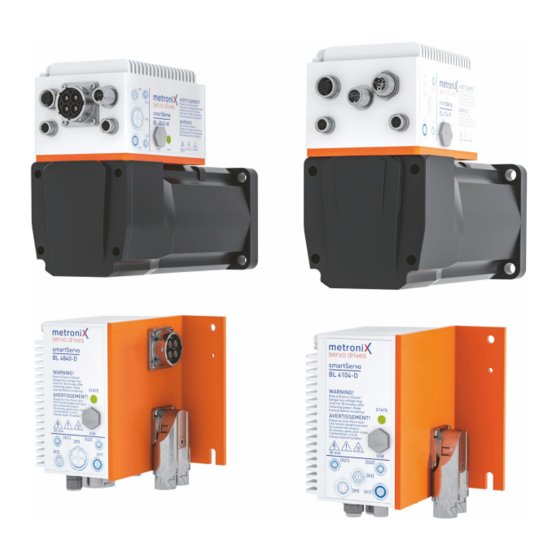
3 Product description Designation Description BL 4840-D A servo drive supplied with 48 V DC, separated from the motor, with 40 A rated current BL 4104-M A motor-mounted servo drive supplied with 230 V and 4 A rated current Device view BL 4000-M Front view Figure 2: Front view of a BL 4800-M (left) and BL 4100-M (right) 1 Warnings... -
Page 19: Device View Bl 4000-D
3 Product description Device view BL 4000-D Front view Figure 4: Front view of a BL 4800-D (left) and BL 4100-D (right) 1 [X6A] Motor connection 5 Connector descriptions 2 Earthing screw 6 Safety Symbols as per ISO 7000 3 Status indicator LED (READY, ERROR, 7 Warnings ENABLE, BLUETOOTH) 4 [X19] USB interface with cover cap... - Page 20 3 Product description Side view Figure 6: Side view of a BL 4800-D (left) and BL 4100-D (right) 1 [X6A] Motor connection 13 [X6] Motor connection BL 4100-D and BL 4800-D (max. 16 A) 11 [X2] Resolver/Multi-encoder Mounting Instructions BL 4000-M and BL 4000-D Page 20 of 95...
-
Page 21: Features
Features All of the servo drives of this series have the following features: Integrated fieldbus interfaces EtherCAT interface (CoE) ProfiNet interface (Metronix standard telegrams, based on PROFIdrive) Integrated universal shaft encoder evaluation for the following encoder types: Resolvers Analogue and digital incremental encoders with and without commutation signals ®... - Page 22 3 Product description Integrated functional safety "Safe Torque Off (STO)" safety function integrated in the device SS1 functionality possible Homing and positioning Integrated positioning control with a wide range of functions as per "CAN in Automation (CiA) DSP402" plus numerous additional application-specific functions.
- Page 23 3 Product description Applications Speed- and angle-synchronous operation with an electronic gear unit via the incremental encoder input or fieldbus. Extensive modes of operation for synchronisation, e.g. "flying saw" Jog mode, teach-in mode, motion programs, torque-limited set control and much more Special control features High control quality due to high-quality sensors, far superior to conventional market...
-
Page 24: Mounting
4 Mounting Mounting Mounting BL 4000-D Figure 7: Dimensions and installation clearance for BL 4800-D (left) and BL 4100-D (right) The following requirements must be fulfilled for the installation of the servo drive: Follow the general set-up and safety rules and regulations concerning the installation. - Page 25 4 Mounting As the Intercontec connector [X6]/[X2] can be turned, the motor/encoder cable can also be connected from the front or from above. Mounting BL 4000-M Servo drives of device family BL 4000-M are usually already mounted on the motor and do not have to be mounted separately.
-
Page 26: Electrical Installation
5 Electrical installation Electrical installation This chapter provides all of the relevant information for the electrical installation of a servo drive of the BL 4000-M / BL 4000-D series with an integrated "Safe Torque Off (STO)" safety function. Notes concerning the safe and EMC- compliant installation 5.1.1 Explanations and terminology... -
Page 27: Bl 4100-M / Bl 4100-D: Proper Wiring
5 Electrical installation 5.1.3 BL 4100-M / BL 4100-D: Proper wiring The following must be observed for servo drives of type BL 4100-M / BL 4100-D to ensure a safe and EMC-compliant design of the drive system: Dangerous electrical voltage! For safety reasons, all of the PE earth (ground) conductors must be connected prior to the initial operation of the system. -
Page 28: Esd Protection
5 Electrical installation 5.1.4 ESD protection Damage to property due to ESD (electrostatic discharge) At unassigned plug connectors, damage can occur to the device or to other system parts as a result of ESD (electrostatic discharge). To prevent this type of damage, comply with the following: Ensure proper earthing of all of the system components and wire the servo drive completely prior to switching on the voltage supply. -
Page 29: Additional Requirements For The Ul Approval
5 Electrical installation Additional requirements for the UL approval Mains power supply protection Integral solid state short circuit protection does not provide branch circuit protection. Branch circuit protection must be provided in accordance with the Manufacturer Instructions, National Electrical Code and any additional local codes. BL 4000-M / BL 4000-D: For Use On A Circuit Capable Of Delivering Not More Than 5000rms Symmetrical Amperes, 240V maximum and When Protected by Circuit Breaker S201UP K16... -
Page 30: Connector Bl 4100-M / Bl 4100-D: Power Supply [X9]
5 Electrical installation Connector BL 4100-M / BL 4100-D: Power supply [X9] Servo drives of the BL 4100-M / BL 4100-D series must be connected to the power supply in accordance with the following illustration: Figure 8: Connecting a BL 4100-M / BL 4100-D to the supply voltage Risk of damage to the servo drive The servo drive will be damaged in the following cases: reverse connection of the 24 V operating voltage connections, excessive operating voltage, or... - Page 31 5 Electrical installation Configuration on the device [X9] Phoenix Contact SACC-CI-M12MSK-4PE-L180 THR T (M12, 5-pin K-coded) Mating connector [X9] 3m Power cable, schielded: SAC-5P- 3,0-PUR/M12FSK PE SH - 1414789 Single plug: SACC-M12FSK-4PECT-CL SH Self-assembly connectors The connectors for self-assembly have a larger outer radius than pre-assembled connectors.
- Page 32 5 Electrical installation Mains filter To comply with the EMC standard, an external mains filter is required between the circuit breaker and the controller: Mains filter Würth 810912010 or comparable. In larger systems with many controllers of the same family, the use of a suitable common mains filter may make more sense.
-
Page 33: Connector Bl 4800-M / Bl 4800-D: Power Supply [X9]
5 Electrical installation Connector BL 4800-M / BL 4800-D: Power supply [X9] Servo drives of the BL 4800-M / BL 4800-D series must be connected to the power supply in accordance with the following illustration: Figure 10: Connecting a BL 4800-M / BL 4800-D to the supply voltage Risk of damage to the servo drive The servo drive will be damaged in the following cases: reverse connection of the 24 V operating voltage connections,... - Page 34 5 Electrical installation Configuration on the device [X9] Amphenol RT00164PNH03 Inserts: male, SC000518S Mating connector [X9] Amphenol RT06164SNH Gasket Amphenol RT0L-16CG-S1 Backshell straight Amphenol RT0B-16CG-S1 Backshell angled Inserts: female, SC000519S Pin assignment [X9] Figure 11: Connector "Power supply [X9]", pin side view Name Specification DC_MINUS_1 Reference potential 48 V power supply DC_MINUS_2 Reference potential 48 V power supply...
-
Page 35: Connector : 24 V Supply And Sto [X3]
5 Electrical installation Connector : 24 V supply and STO [X3] Risk of damage to the servo drive The servo drive will be damaged in the following cases: reverse connection of the 24 V operating voltage connections, excessive operating voltage, or accidental interchanging of the operating voltage and motor connectors. - Page 36 5 Electrical installation Name Specification STOA Control input A for the STO function GNDA Reference potential for STOA STOB Control input B for the STO function GNDB Reference potential for STOB DIN6 Digital input 6 (limit switch 0) DIN7 Digital input 7 (limit switch 1) 24 V 24 V supply Reference potential for 24 V supply...
-
Page 37: Connector Bl 4100-M: Motor [X6], [X6B]
5 Electrical installation Connector BL 4100-M: motor [X6], [X6B] On BL 4100-M type devices, the motor is connected via a PCB connector ([X6], see the following figure, label A), before the servo drive is mounted on the motor. The motor is connected to the terminals U,V,W. A possibly existing motor holding brake can be connected via a PCB terminal with push-in technology [X6B] (Label B). - Page 38 5 Electrical installation Pin assignment Figure 14: Pin assignment: motor connector (motor with hoding brake) [X6], [X6B]“ Pin X6 Name Specification Motor phase W Motor phase V Motor phase U Protective earth conductor of the motor Pin X6B Name Specification Holding brake + Holding brake - Risk of injury...
- Page 39 5 Electrical installation Connection notes [X6] Assemble the connector [X6] according to the manufacturer's specifications. To maintain the necessary safety distance, pin 4 must not be equipped with a crimp contact. An existing holding brake in the motor is connected to the terminals BR+ and BR- of [X6B].
-
Page 40: Connector Bl 4100-D: Motor [X6]
5 Electrical installation Connector BL 4100-D: motor [X6] On BL 4100-D type devices, the motor is connected via a Intercontec connector. The motor is connected to the terminals U,V,W. An analogue motor temperature sensor can be connected to the terminals MT+ and MT- if it is routed together with the motor phases in one cable. - Page 41 5 Electrical installation ® Pin assignment: motor connector (HIPERFACE DSL ® Figure 16: Pin assignment: „motor connector (HIPERFACE DSL ) [X6]“ Name Specification Motor phase U Motor phase V Motor phase W Protective earth conductor of the motor MT-/ DSL- HIPERFACE DSL - Holding brake + Holding brake - DSL+...
- Page 42 5 Electrical installation Connection notes [X6] Connect the inner and outer cable shield to the connector housing according to the connector manufacturer's specifications. An existing holding brake in the motor is connected to the terminals BR+ and BR-. When connecting the holding brake, be sure to observe the maximum output current provided by the servo drive.
-
Page 43: Connector Bl 4800-M: Motor [X6]
5 Electrical installation Connector BL 4800-M: motor [X6] On BL 4800-M type devices, the motor is connected via threaded terminals on the power unit PCB ([X6], see the following Figure, Label C), before the servo drive is mounted on the motor. A possibly existing motor holding brake can be connected via a PCB terminal with push-in technology [X6B] (Label A). - Page 44 5 Electrical installation Pin X6 Name Specification Motor phase U Motor phase V Motor phase W Pin X6B Name Specification Holding brake + Holding brake - Risk of injury The brake output of the servo drive (BR+, BR-) must not be used as the sole stop element in safety-oriented applications.
-
Page 45: Connector Bl 4800-D: Motor [X6], [X6A]
5 Electrical installation Connector BL 4800-D: motor [X6], [X6A] On BL 4800-D type devices, the motor is connected via an Amphenol connector [X6A]. The motor is connected to the terminals U,V,W. An analogue motor temperature sensor can be connected to the terminals MT+ and MT- if it is routed together with the motor phases in one cable. - Page 46 5 Electrical installation Pin X6 Name Specification Motor temperature sensor + MT-/ DSL- Motor temperature sensor - Holding brake + Holding brake - DSL+ ® Pin assignment: motor connector (HIPERFACE DSL ® Figure 20: Pin assignment: „motor connector (HIPERFACE DSL ) [X6], [X6A]“ Pin X6A Name Specification Motor phase U...
- Page 47 5 Electrical installation Connector Cable type (2 x (2 x 0,75 mm²)) (3 x 4 mm²) Comply with the required minimum cross-section Always observe the minimum cross-sections for the lines U, V and W. Connection notes [X6] Connect the outer cable shield to the connector housing according to the connector manufacturer's specifications.
-
Page 48: Connector Bl 4000-D: Resolvers And Encoder [X2]
If an incorrect power supply is used, the encoder may be destroyed. Ensure that the correct voltage is activated prior to connecting the encoder to [X2]. To do so, start the ® Metronix ServoCommander parameterisation software and select the Parameters/Device parameters/Angle encoder settings. - Page 49 5 Electrical installation Configuration on the device [X2] Intercontec Double-Receptacles angled rotatable EEDA107NN00000002000, 15 pin female inserts Mating connector [X2] ESTA204MR03330003000, 7x Pin 61.232.11, 1x Pin 61.231.11 (Contact A) Pin assignment: resolvers Figure 22: Pin assignment „resolvers [X2]“ Pin Name Specification Carrier signal for the resolver S4/SIN-...
- Page 50 5 Electrical installation Pin assignment: analogue incremental encoders Figure 23: Pin assignment: „analogue incremental encoders [X2]“ Pin Name Specification Operating voltage for incremental encoders Associated reference potential Motor temperature sensor, normally closed contact, PTC, NTC, KTY Index pulse track signal (differential) of the high- resolution incremental encoder COS_Z1 / D+ COSINE commutation signal (differential) of the high-...
- Page 51 5 Electrical installation Pin assignment: incremental encoder with a serial interface Figure 24: Pin assignment:„incremental encoder with a serial interface [X2]“ Name Specification Operating voltage Associated reference potential Motor temperature sensor, normally closed contact, PTC, NTC, ® DATA / SL+ Bidirectional RS485 data line (differential) (EnDat/HIPERFACE BISS) #DATA / SL-...
- Page 52 5 Electrical installation Pin assignment: digital incremental encoder (RS422) Figure 25: Pin assignment: „digital incremental encoder (RS422) [X2]“ Name Specification Operating voltage for incremental encoders Associated reference potential Motor temperature sensor, normally closed contact, PTC, NTC, N / U Index pulse RS422 (differential) of the digital incremental encoder #N / U HALL_U Phase U of the Hall sensor for commutation...
-
Page 53: Connector Bl 4000-M: Resolvers And Encoder [X2]
5 Electrical installation 5.11 Connector BL 4000-M: resolvers and encoder [X2] On BL 4100-M type devices, the angle encoder is connected via a PCB connector [X2], see the following Figure (C), before the servo drive is mounted on the motor. Figure 26: Connector arrangement: motor [X6], holding brake [X6B] and angle encoder [X2] Different types of encoders can be connected to the Molex connector (see also section 6.7 Resolver and encoder connector [X2] on page 76):... - Page 54 If an incorrect power supply is used, the encoder may be destroyed. Ensure that the correct voltage is activated prior to connecting the encoder to [X2]. To do so, start the ® Metronix ServoCommander parameterisation software and select the Parameters/Device parameters/Angle encoder settings.
- Page 55 5 Electrical installation Pin assignment: analogue incremental encoders Figure 29: Pin assignment: „analogue incremental encoders [X2]“ Pin Name Specification Operating voltage for incremental encoders Associated reference potential Motor temperature sensor, normally closed contact, PTC, NTC, KTY Index pulse track signal (differential) of the high- resolution incremental encoder COS_Z1 / D+ COSINE commutation signal (differential) of the high-...
- Page 56 5 Electrical installation Pin assignment: incremental encoder with a serial interface Figure 30: Pin assignment:„incremental encoder with a serial interface [X2]“ Name Specification Operating voltage Associated reference potential Motor temperature sensor, normally closed contact, PTC, NTC, ® DATA / SL+ Bidirectional RS485 data line (differential) (EnDat/HIPERFACE BISS) #DATA / SL-...
- Page 57 5 Electrical installation Pin assignment: digital incremental encoder (RS422) Figure 31: Pin assignment: „digital incremental encoder (RS422) [X2]“ Name Specification Operating voltage for incremental encoders Associated reference potential Motor temperature sensor, normally closed contact, PTC, NTC, N / U Index pulse RS422 (differential) of the digital incremental encoder #N / U HALL_U Phase U of the Hall sensor for commutation...
-
Page 58: Connector: Usb [X19]
5 Electrical installation 5.12 Connector: USB [X19] The BL 4000-M / BL 4000-D servo drive has a Type Mini-B USB connector. The correct operation requires a short USB cable (< 3 m) and the correct installation and earthing of the servo drive. If excessive malfunctions/faults lead to communication problems (frozen communication), the USB connector can be briefly disconnected to restart the communication. ... -
Page 59: Connector: Real-Time Ethernet [X21], [X22]
5 Electrical installation 5.13 Connector: real-time Ethernet [X21], [X22] The connection to an EtherCAT or PROFINET network is made via two M8 connectors according to IEC 61076-114 (4-pin, socket, D-coded). Details can be found in the Fieldbus manuals. Configuration on the device [X21], [X22] Flush-type connector, Ethernet/PROFINET Phoenix Contact, SACC-CIP-M8FSD-4P SMD SH R32 - 1068454 Mating connector [X21], [X22]... -
Page 60: Connector: I/O Interface [X1]
5 Electrical installation 5.14 Connector: I/O interface [X1] The analogue input (AIN) and the analogue output (AOUT) are rated for voltages in the range ± 10 V. Both the analogue inputs and the analogue output must be connected to the controller via twisted and shielded cables. - Page 61 5 Electrical installation Pin assignment [X1] Figure 34: I/O interface [X1] Pin Name Specification DIN0 Digital input 0 DIN1 Digital input 1 DIN2 Digital input 2 DIN3 Digital input 3 DIN4 Digital input 4 DIN5 Digital input 5 (servo drive enable signal) DIN8 Digital Input (flying saw, sampling) DOUT0...
-
Page 62: Technical Data
6 Technical data Technical data This chapter provides all of the relevant technical data of the BL 4000-M / BL 4000-D servo drives with an integrated "Safe Torque Off (STO)" safety function. General technical data Qualification Characteristic Value Low Voltage Directive 2014/30/EU by applying the harmonised standard EN 61800-5-1 See section 9.1 CE conformity (EMC, RoHS, Low Voltage Directive) on page 88... - Page 63 6 Technical data Compliance with the pollution degree rating The integrated safety technology requires compliance with pollution degree rating 2 and thus a protected enclosure (IP54). This must always be ensured through appropriate measures. Use in residential environment In a residential environment, servo drives of the BL 4000-M / BL 4000-D device family can cause high-frequency interference, which makes interference suppression measures necessary.
-
Page 64: Bl 4100-M / Bl 4100-D: Power Supply [X9]
6 Technical data BL 4100-M / BL 4100-D: Power supply [X9] Power data Characteristic Value Supply voltage 1 x 75...230 VAC [± 10 %], 50 ... 60 Hz Supply network type TN, TT Maximum mains current in continuous operation (S1) * DC bus voltage 325 VDC (with U = 230 VAC) mains... -
Page 65: Bl 4800-M / Bl 4800-D: Power Supply [X9]
6 Technical data BL 4800-M / BL 4800-D: Power supply [X9] Power data Characteristic Value Supply voltage 24 ... 48 VDC [± 10 %] Maximum mains current in continuous operation 40 A (S1) DC bus voltage corresponds to the supply voltage Supplying with power supply unit The power supply unit used must be able to charge the capacitive load of the DC link capacitors with current limitation when switched on. -
Page 66: Supply And Sto [X3]
6 Technical data 24 V supply and STO [X3] 24 V supply Characteristic Value 24 V supply 24 VDC [± 20 %] (0.2 A) *1) plus the current consumption of the I/O's and a possibly existing holding brake. Characteristic values Characteristic Value Safety level... -
Page 67: Time Response
6 Technical data Response time until power output stage inactive and maximum OSSD test pulse duration The typical response time and the maximum test pulse duration depend on the input voltage at STOA/STOB: Characteristic Value Input voltage (STOA/STOB) 19.2 V 24 V 28.8 V Typical response time... - Page 68 6 Technical data Figure 35: Time response of the activation of the STO safety function with a restart see section 0.1 Operating mode and error indication on page 1 Time Description Value Maximum permissible discrepancy time 100 ms DCRP without the servo drive issuing an error STOA/B –...
-
Page 69: Time Response Of The Ss1 Activation During Operation With A Restart
6 Technical data 6.4.2.2 Time response of the SS1 activation during operation with a restart Figure 36: Time response during the activation of the SS1 safety function (external switching) with a restart see section 0.1 Operating mode and error indication on page 1 Mounting Instructions BL 4000-M and BL 4000-D Page 69 of 95... - Page 70 6 Technical data Time Description Value Delay between the switching of S1 and the See the data sheet of the closing of the undelayed contact K1 safety relay Delay between S1 and the opening of the off- Can be adjusted on the K1_delay delayed contacts K1 safety relay...
-
Page 71: Bl 4100-M / Bl 4100-D: Motor Connector [X6]
6 Technical data BL 4100-M / BL 4100-D: Motor connector [X6] Performance data Supply voltage 230 VAC [± 10 %], 50 Hz, f = 5 kHz, f > 2 Hz, = 30°C Ambient Characteristic BL 4104-D BL 4104-M Nominal output power 800 W 700 W Maximum output power for 2 s 2400 W 2400 W Nominal output current... - Page 72 6 Technical data Motor temperature monitoring system Dangerous electrical voltage! The signals for the temperature sensor "MT-" and "MT+" at the motor connector [X6] must be connected to protective extra-low voltage (PELV) on the motor side and they must be insulated against the motor phases. Electronic overload protection of the motor The servo drive has an electronic cut-out for overload protection combined with thermal memory retention.
- Page 73 6 Technical data ® HIPERFACE DSL connector [X6] Characteristic Value HPF_DSL-, HPF_DSL+ In accordance with the ® HIPERFACE DSL specification RS485 Baud rate 9.37 MHz Frame rate 12.1 to 27 µs Supply voltage 10 V (250 mA) Supported transfer modes Transfer of short and long messages with storage of the set of parameters in the encoder 110 Ω...
-
Page 74: Bl 4800-M / Bl 4800-D: Motor Connector [X6]
6 Technical data BL 4800-M / BL 4800-D: Motor connector [X6] Performance data With supply voltage 48 VDC [± 10 %], f = 5 kHz, f > 3 Hz, = 30°C Ambient Characteristic BL 4840-M BL 4840-D Nominal output power 1.0 kW 1.1 kW Maximum output power for 2 s 3.6 kW Nominal output current 40 A... - Page 75 6 Technical data Electronic overload protection of the motor The servo drive has an electronic cut-out for overload protection combined with thermal memory retention. For an effective protection, the nominal motor current, maximum motor current and overload time (I t time) must be parameterised as described in the product manual.
-
Page 76: Resolver And Encoder Connector [X2]
6 Technical data Resolver and encoder connector [X2] The correct parameterisation of the multi-encoder interface is described in section „Encoder“ tab in the Product manual smartServo BL 4000-D / smartServo BL 4000-M. Possibly not all encoders of a manufacturer are supported It is possible that not all encoders of a manufacturer are fully supported. In individual cases it is therefore always recommended to test the encoder in advance in the intended application. - Page 77 6 Technical data Digital incremental encoders Digital incremental encoders with RS422-compatible A/B/N signals with a line count of up to 16,384 lines can be connected (e.g. ERN 420). In addition, Hall generator signals with a TTL level for determining the commutation position can also be connected. Characteristic Value Parameterisable number of encoder lines...
- Page 78 6 Technical data ® HIPERFACE encoders ® Shaft encoders with HIPERFACE made by Sick-Stegmann are supported in the single- turn and multi-turn variants. The following encoder models can be connected: Single-turn SinCos encoders: SCS 60/70, SKS 36, SRS 50/60/64, SEK 34/37/52 Multi-turn SinCos encoders: SCM 60/70, SKM 36, SRM 50/60/64, SEL 34/37/52 Single-turn SinCos encoders for hollow shaft drives: SCS-Kit 101, SHS 170, SCK 25/35/40/45/50/53...
-
Page 79: Usb [X19]
The support of these fieldbus types is integrated in the servo drive. Additional modules are not required. The parameterisation is performed with the aid of the ® Metronix ServoCommander . For further information about the fieldbus connection, see the fieldbus-specific product manuals section 1.2 Additional documents on page 7. -
Page 80: I/O Interface [X1]
6 Technical data Compatibility with servo drives of the ARS 2000 series The behaviour on the bus and the object directory is largely compatible with the behaviour of the ARS 2000 series. There are certain differences, e.g. in terms of the device IDs (CANopen product_code ID 1018_02). - Page 81 6 Technical data Analogue input AIN Characteristic Value ± 10 V Input range Resolution 12 Bit Filter time configurable: 2 x t to 200 ms corresponds to the configurable current controller cycle time Analogue output AOUT Characteristic Value ± 10 V Output voltage ±...
- Page 82 6 Technical data Master frequency output [X1] The connector [X1] also accommodates the master frequency output (encoder emulation). To use this function, [X1] must be configured as the master frequency output. Characteristic Value Number of lines Programmable 1 to 2 and 2 lines/revolution Track signals A, B...
-
Page 83: Time Response Of The Digital Inputs
6 Technical data 6.10.1 Time response of the digital inputs The digital inputs are digitally filtered to improve the interference suppression. The following illustration shows the filter time mechanism. In addition, the special reaction to the "Positioning start" function is also shown. Although the signal is evaluated during the position controller cycle t the start of a movement will be performed within the interpolation cycle time matrix t... -
Page 84: Time Response Of The Digital Outputs
6 Technical data 6.10.2 Time response of the digital outputs Figure 38: Filter time mechanism in the case of digital outputs Parameter Value Delay caused by the firmware t DOUT_ON DOUT_OFF DOUT t typically 100 µs HW, ON DOUT t typically 300 µs HW, OFF typically 100 ms with 2 A RISE... -
Page 85: Time Response During Power On
6 Technical data 6.10.3 Time response during power ON Figure 39: Time diagram of the servo drive Parameter Min. Typ. Max. Start of the firmware after power ON t boot Encoder start time t 0.7 s ® (resolver) (HIPERFACE DSL DC bus charging time t Output stage active after servo drive 6 ms enabling t... -
Page 86: Storage/Transport
7 Storage/transport Storage/transport The following requirements must be fulfilled for the storage and transport of the servo drive: Storage Store the servo drive in line with the specified storage temperatures. Use only its original packaging. After approximately six months of storage, the oxide layer of the capacitors may become damaged. -
Page 87: Maintenance, Cleaning, Repair And Disposal
8 Maintenance, cleaning, repair and disposal Maintenance, cleaning, repair and disposal The following requirements must be fulfilled for the maintenance, cleaning, repair and disposal of the servo drive: Maintenance Servo drives of the BL 4000-M / BL 4000-D device series are maintenance-free. Cleaning Damage to the servo drive due to improper cleaning To remove surface soiling, e.g. -
Page 88: Appendix
9 Appendix Appendix CE conformity (EMC, RoHS, Low Voltage Directive) BL 4100-M / BL 4100-D Mounting Instructions BL 4000-M and BL 4000-D Page 88 of 95... - Page 89 9 Appendix BL 4800-M / BL 4800-D Mounting Instructions BL 4000-M and BL 4000-D Page 89 of 95...
-
Page 90: Ce Conformity (Machinery Directive)
9 Appendix CE conformity (Machinery Directive) BL 4000-M / BL 4000-D Mounting Instructions BL 4000-M and BL 4000-D Page 90 of 95... - Page 91 9 Appendix Mounting Instructions BL 4000-M and BL 4000-D Page 91 of 95...
-
Page 92: Curus Certification
9 Appendix cURus certification BL 4000-M / BL 4000-D Mounting Instructions BL 4000-M and BL 4000-D Page 92 of 95... - Page 93 9 Appendix Mounting Instructions BL 4000-M and BL 4000-D Page 93 of 95...
- Page 94 9 Appendix Mounting Instructions BL 4000-M and BL 4000-D Page 94 of 95...
- Page 95 9 Appendix Mounting Instructions BL 4000-M and BL 4000-D Page 95 of 95...
Need help?
Do you have a question about the smartServo BL 4000-D Series and is the answer not in the manual?
Questions and answers