Table of Contents
Advertisement
Applications Guide
Contents
Introduction .................................................................................................................................... 3
Important Notices........................................................................................................................... 3
Actuator Torque Selection ............................................................................................................... 4
Heat/Cool/VAV Applications (with the CTE-5202 Thermostat) ....................................................... 4
Accessories ..................................................................................................................................... 5
Ball Joint and Crank Arms ............................................................................................................ 5
Enclosure, Cord Grip, and Wiring Kits ......................................................................................... 6
Mounting (Non-Rotation) Brackets .............................................................................................. 7
Thermostat .................................................................................................................................. 7
Transformers ................................................................................................................................ 7
VEB-4x Series Valves Mounting/Repair Kits ................................................................................. 8
Troubleshooting .............................................................................................................................. 9
Auxiliary Switch Does Not Work ................................................................................................. 9
Fail-Safe Does Not Work .............................................................................................................. 9
Feedback Does Not Work ............................................................................................................ 9
No Rotation ................................................................................................................................. 9
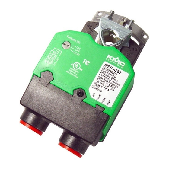
MEP-4xxx Direct-Coupled Actuators (40 to 90 in-lb.)
Direct-Coupled Actuators (40 to 90 in-lb.)
1
MEP-4xxx
Applications Guide, AN0513A Rev. J
Advertisement
Table of Contents

Related Manuals for KMC Controls MEP-4002


Summarization of Contents
Important Notices
Electrical Safety Warning
Risk of electrical shock in line-voltage models. Disconnect power before servicing.
Grounding Warning
If both conduit connections are used, they must be externally connected for grounding.
Accessories
Ball Joint and Crank Arms
Details on HLO-4001 crank arm kit, VTD-0804 ball joint, and VTD-14xx crank arms.
Enclosure, Cord Grip, and Wiring Kits
Enclosure Kit
Metal mounting plate, plastic cover for protection from inclement conditions.
Cord Grip
Liquid-tight cord grip for IP54 rating, accepts 0.18 to 0.40" diameter cables.
Wiring Kits
Assembled kits with cord grip, cable, and terminal block for specific actuator series.
Mounting (Non-Rotation) Brackets
HMO-4002 Non-Rotation Bracket
Provided with MEP-40xx/48xx/425x/455x actuators, not for MEP-427x/457x/49xx.
HMO-4004 Non-Rotation Bracket Kit
Kit for mounting non-rotation brackets to ball valves.
HMO-4001 Non-Rotation "T" Bracket
Used instead of HMO-4002 to span open distance or bent for spacing.
VEB-4x Series Valves Mounting/Repair Kits
HPO-5074 Kit
For adapting valve bodies for "quick mounting" MEP-4xxxV actuators.
HPO-5073 Kit
Repair kit for VEP/VEB ball valves with standard MEP-4xxx actuators.
Troubleshooting
Auxiliary Switch Issues
Check switch setting and wiring for auxiliary switch problems.
Fail-Safe Operation Issues
Check fail-safe direction switch and consider initial power-up delay.
Feedback Issues
Check feedback switch setting and wiring for feedback problems.
No Rotation
Check direction switches and initial power-up capacitor charging delay.
Rotation Direction Errors
Check directional switches and fail-safe direction switch settings.
Incorrect Stroke Range
Check auto-mapping, adjustable stop, and controller voltage.
Configuration
Proportional Models Setup
Details on input/feedback options and selectable features for MEP-4xx2 models.
Tri-State/2-Position Rotation Direction
Non-fail-safe Models
Setting the slide switch for rotation direction on MEP-4xx1/4x13 models.
Fail-safe/Fast-acting Models
Using selector switches for rotation direction on MEP-4x51/4x01 models.
Auxiliary Switch Adjustment
Method 1: Dial Degrees
Adjusts the auxiliary switch trip point by setting desired degrees on the dial.
Method 2: Rotation Position
Adjusts the auxiliary switch trip point based on the actuator's rotation position.
Need help?
Do you have a question about the MEP-4002 and is the answer not in the manual?
Questions and answers