Table of Contents
Advertisement
Quick Links
Applications Guide
Contents
Important Notices........................................................................................................................... 2
Introduction .................................................................................................................................... 2
Torque Requirements for Dampers ................................................................................................. 2
Models ............................................................................................................................................ 3
Accessories ..................................................................................................................................... 4
Auxiliary Switches and End Stops ................................................................................................ 4
Transformers ................................................................................................................................ 4
Enclosure, Cord Grip, and Wiring Kits ......................................................................................... 4
Thermostat .................................................................................................................................. 4
Mounting Brackets and Crank Arm Kit ......................................................................................... 5
Master/Slave Wiring........................................................................................................................ 6
All Master/Slave Combinations .................................................................................................... 6
MEP-7802/7852 Proportional Actuators ...................................................................................... 6
MEP-7801/7803 Tri-State Actuators ............................................................................................. 7
MEP-7851/7853 Tri-State with Fail-Safe Actuators....................................................................... 7
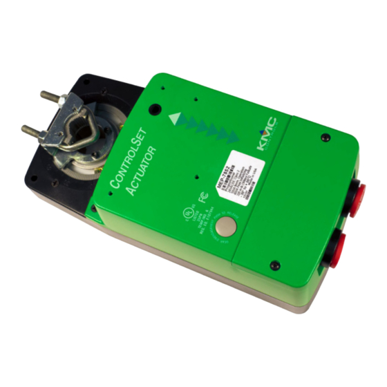
MEP-7xxx Direct-Coupled Actuators (up to 320 in-lb.)
Direct-Coupled Actuators (up to 320 in-lb.)
1
MEP-7xxx
Applications Guide, AN1113A Rev. D
Advertisement
Table of Contents

Related Manuals for KMC Controls MEP-7 Series


Summary of Contents for KMC Controls MEP-7 Series
-
Page 1: Table Of Contents
MEP-7xxx Direct-Coupled Actuators (up to 320 in-lb.) Applications Guide Contents Important Notices........................... 2 Introduction ............................ 2 Torque Requirements for Dampers ....................2 Models ............................3 Accessories ............................. 4 Auxiliary Switches and End Stops ....................4 Transformers ..........................4 Enclosure, Cord Grip, and Wiring Kits ..................4 Thermostat .......................... - Page 2 Configuration ..........................8 Troubleshooting ..........................8 Auxiliary Switch Does Not Work ....................8 Fail-Safe Does Not Work ......................8 Feedback Does Not Work ......................8 No Rotation ..........................8 Rotation in Wrong Direction ....................... 9 Stroke Range Is Wrong ........................ 9 Wiring Issues ..........................
-
Page 3: Important Notices
In no event shall tion, see the MEP-7200/7500/7800 Series Installation KMC Controls, Inc. be liable for any damages, direct Guide. or incidental, arising out of or related to the use of For possible proportional heating/cooling applica- this document. -
Page 4: Models
Models Torque Control Built-in Options 180 in-lb. 320 in-lb. 0–10 VDC, 2–10 Feedback: Feedback: Model # Tri-state (20 N•m) (36 N•m) VDC, or 4–20 mA 10K ohm 0/1–5 or Fail Safe (Floating) min. min. Proportional Potentiometer 0/2–10 VDC MEP-7x01 MEP-7x02 MEP-7x03 7500 series 7800 series... -
Page 5: Accessories
Accessories Auxiliary Switches and End Stops Enclosure, Cord Grip, and Wiring Kits HCO-1152 enclosure CME-7001/7002 rotary kit, consisting of a metal switches (SPDT or dual mounting plate, plastic SPDT) are designed to cover, non-rotation brack- start and stop auxiliary et, plug caps, and screws, items (such as electric heat is designed to protect or fans) or to indicate an... -
Page 6: Mounting Brackets And Crank Arm Kit
Mounting Brackets and Crank Arm Kit HMO-4535 non-rotation bracket is provided with each actuator. It can span an open distance, or be formed (bent) into a shape that increases the dis- tance between the mounting surface and the actua- tor. HLO-1020 crank arm kit is used when direct mounting of the actuator is impractical. -
Page 7: Master/Slave Wiring
Master/Slave Wiring All Master/Slave Combinations 1. Follow the instructions in the Wiring (General) 3. On applicable models, set the Master and the section of the MEP-7200/7500/7800 Series Slave’s FAIL switches according to the relevant Installation Guide and also include the following illustration and chart. -
Page 8: Mep-7801/7803 Tri-State Actuators
MASTER SLAVE MEP-7801/7803 Tri-State Actuators 24 VAC/VDC Power In (MEP-7801/7803 Opposite Mount) 24 VAC/VDC Power In 24 VAC/VDC (MEP-7801/7803 Opposite Mount) Control Signal Common Power In MASTER SLAVE 0–10 VDC Control Signal 24 VAC/VDC Control Signal Common (MEP-7802/7852 Opposite Mount, 0–10 VDC Input) MASTER SLAVE 0–5 or 0–10 VDC Feedback Signal... - Page 9 Configuration Troubleshooting For direction, feedback, and auto-mapping setup, Auxiliary Switch Does Not Work see the MEP-7200/7500/7800 Series Installation • Check the auxiliary switch setting. See the Guide. CME-7001/7002 Auxiliary Switches Installation NOTE: Before Jan. 2014, MEP-7xx2 proportional Guide. models had (besides the 4-20 mA input) a 0–10 VDC input and 0–5 or 0–10 VDC •...
- Page 10 Index Symbols Rotation in Wrong Direction 0-5/0-10 vs. 1-5/2-10 VDC Feedback: 4, • For tri-state models, check the CW/CCW wiring. 0-10 vs. 2-10 VDC Inputs: • For proportional models, check the position of 4-20 mA: the direction switch (Switch 2). See Configura- tion on page Accessories:...
- Page 11 Feedback Voltage: Rotation Direction: 7, 8, KMC Controls 19476 Industrial Drive New Paris, IN 46553 574.831.5250 Fax 574.831.5252 www.kmccontrols.com info@kmccontrols.com MEP-7xxx Direct-Coupled Actuators (up to 320 in-lb.) Applications Guide, AN1113A Rev. D © 2017 KMC Controls, Inc. AN1113A Rev. D...
Need help?
Do you have a question about the MEP-7 Series and is the answer not in the manual?
Questions and answers