Advertisement
Quick Links
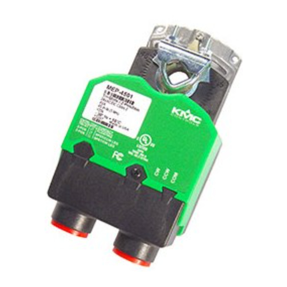
Mounting
2.812
(71.4)
1.563
(39.7)
Gear
Disengagement
Lever
Removeable Conduit Fitting with
(2)1/2" NPS Threaded Holes (for
use with flexible conduit only)
1. Ensure the damper can move freely through its
entire range of motion, and fix any binding before
installing the actuator. Turn the damper blade to
its fully closed position.
2. Press (to the right) and hold the gear disengage-
ment lever (see Illustration 1), rotate the actuator
to the fully closed position, and release the lever.
NOTE: Depending on the damper-seal design,
backing the actuator off its stop
approximately 5° may provide tight
damper shut-off.
3. Align the actuator and slide it onto the shaft.
4. Leaving a gap between the actuator and
mounting surface to prevent any binding, finger-
tighten the nuts on the V-bolt.
MEP-4201/4501/4901
Tri-State/Two-Position Actuators (25/45/90 in-lb.)
Installation Guide
1.625
(41.3)
6.000
(152.4)
Illustration 1—Overview (Direct-Coupled Mounting)
Adjustable
Stop
° Rotation
Indicators
3.406
(86.5)
5. Insert the provided (HMO-4001/4002, dependent
on model) non-rotation bracket into the slot at the
base of the actuator and secure the non-rotation
bracket with two #8 or #10 self-tapping screws.
6. Evenly tighten the V-bolt nuts (30–35 in-lbs.
on MEP-4201 model or 60–70 in-lbs. on MEP-
4501/4901).
7. If desired, use a 7/64-inch hex key wrench to
loosen and position the end-stop screw.
NOTE: The two holes at the top of the actuator
are NOT for use in direct-coupled
applications. (They are for remote
mounting, such as with the optional
HLO-4001 Crank Arm Kit.) For mounting
to valves, see the appropriate valve
installation guide.
1
MEP-4201/4501/4901
HMO-4001 Non-Rotation "T"
Bracket included with MEP-4901
HMO-4002 Non-Rotation
Bracket included with
MEP-4201& MEP-4501
Gear
Disengagement
Lever
HMO-4002
Non-Rotation
Bracket
Mounting
Surface
Installation Guide
Advertisement

Subscribe to Our Youtube Channel
Related Manuals for KMC Controls MEP-4201


Summary of Contents for KMC Controls MEP-4201
- Page 1 2. Press (to the right) and hold the gear disengage- 6. Evenly tighten the V-bolt nuts (30–35 in-lbs. ment lever (see Illustration 1), rotate the actuator on MEP-4201 model or 60–70 in-lbs. on MEP- to the fully closed position, and release the lever. 4501/4901).
- Page 2 KMC Controls, Inc. 19476 Industrial Drive – Power Supply Contact Position: New Paris, IN 46553 Open = CCW Rotation 24 VAC/VDC 574.831.5250 Closed = CW Rotation www.kmccontrols.com info@kmccontrols.com Illustration 4—Two-Position Control, CW Leg MEP-4201/4501/4901 Installation Guide © 2013 KMC Controls, Inc. 039-019-02B...
Need help?
Do you have a question about the MEP-4201 and is the answer not in the manual?
Questions and answers