
Related Manuals for KMC Controls KMD-5831


Summary of Contents for KMC Controls KMD-5831
- Page 1 Installation & Operation Guide (Shown with optional Override Board Cover) KMD-5831 Programmable Loop Controller PLC-28 Direct Digital Controller 902-019-04B...
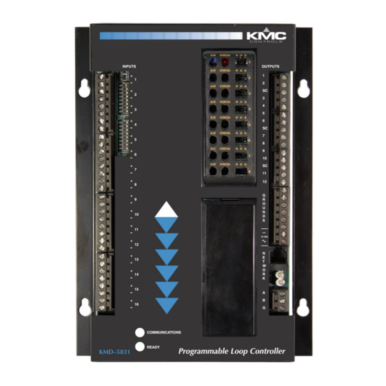
- Page 2 Direct Digital Controllers. Review this material before you attempt to install the controller. For clarity we will focus on the KMD-5831 but all installation and operating instructions apply equally to the KMD-5821. Illustration 1 shows the major controller components and their locations. The KMD-5821has fewer inputs and outputs.
-
Page 3: Installation
Installation This section provides important instructions and guidelines for installing the KMD-5831 Programmable Loop Controller PLC-28 Direct Digital Controller. Carefully review this information prior to attempting installation. Mounting Use the four mounting holes to securely mount the controller using #6 hardware inside a UL-approved Enclosed Energy Management Equipment Panel or other suitable protective enclosure. -
Page 4: Connecting Outputs
Installation KMD-5831 PLC-28 Direct Digital Controller Installation & Operation Guide ◆ If input pull-ups are required, refer to “Configuration” later in this section. ◆ Wiring terminals are suitable for up to two 12–22 AWG wires. If more than two wires are required, use an external terminal strip for additional connec- tions. - Page 5 KMD-5831 PLC-28 Direct Digital Controller Installation & Operation Guide Installation ◆ Connect the shields to an earth ground (DO NOT use a chassis ground) only at one end of the segment; tape back the shield ground at the other end.
-
Page 6: Override Cards
Installation KMD-5831 PLC-28 Direct Digital Controller Installation & Operation Guide Override Cards For large relays or devices that cannot be powered directly from a standard output, you will need to install an output override card. Override cards provide: ◆ a wide choice of output signals. - Page 7 KMD-5831 PLC-28 Direct Digital Controller Installation & Operation Guide Installation Caution DO NOT connect active 24 VAC circuits to the output block unless the associ- ated jumper is removed first. Doing so will result in damage to the output and prevent it from working.
- Page 8 Installation KMD-5831 PLC-28 Direct Digital Controller Installation & Operation Guide Input Pull-ups A 10K ohm resistor is available as a pull-up to a +5 VDC source voltage for passive or ‘dry” inputs on each input circuit. The resistor is switched “On” or “Off”...
-
Page 9: Power Connection
KMD-5831 PLC-28 Direct Digital Controller Installation & Operation Guide Installation Illustration 7 shows the switch in greater detail Illustration 7. RS-485 End-of-Line Switch Detail If the controller is located at the end of the network segment the switches must both be placed in the default “ON” position. Otherwise, place the switches in the “OFF”... -
Page 10: Operation
Operation Once configured, programmed and powered up, the controller requires very little user intervention. Controls and Indicators The following sections describe the controls and indicators found on the card. Alternately, you may remove the RS-485 terminal block from the card to isolate the card from the network without disrupting network communications to other controllers. - Page 11 KMD-5831 PLC-28 Direct Digital Controller Installation & Operation Guide Operation Note Resetting the controller will restore the factory default configuration. If the devices cannot communite with the controller, or the controller cannot commnicate with other controllers, it may be necessary to re-configure the controller with HCM to establish normal communications and operation.
-
Page 12: Important Notices
The contents and the product(s) described herein are subject to change without notice. KMC Controls, Inc. makes no representations or warranties with respect to this document. In no event shall KMC Controls, Inc. be liable for any damages, direct or incidental, arising out of or related to the use of this document.
Need help?
Do you have a question about the KMD-5831 and is the answer not in the manual?
Questions and answers