KMC Controls CSC-3000 Series Application Manual
Pneumatic vav reset volume controllers
Hide thumbs
Also See for CSC-3000 Series:
- Application manual (3 pages) ,
- Application manual (13 pages)
Table of Contents
Advertisement
Applications Guide
*NOTE: This Application Guide does not apply
(completely) to the CSC-3014 or the
CSC-3501/3505. See their separate data
sheets and installation guides.
General Information ..................................................................................................... 2
CSC-3000 Series Overview ............................................................................................................................................ 2
Mounting ....................................................................................................................................................................... 2
More Information .......................................................................................................................................................... 2
Connections .................................................................................................................................................................. 3
Adjustments and Calibration ......................................................................................................................................... 4
Damper Action ........................................................................................................................................................ 4
Determining the Type of Reset ................................................................................................................................ 4
Adjusting Minimums and Maximums ...................................................................................................................... 4
DIRECT Reset Minimum and Maximum .................................................................................................................. 4
REVERSE Reset Minimum and Maximum ................................................................................................................ 5
Reset Start Point ...................................................................................................................................................... 6
Reset Span ............................................................................................................................................................... 6
Troubleshooting ............................................................................................................................................................. 7
Maintenance .................................................................................................................................................................. 7
Important Notices ......................................................................................................................................................... 7
Magnehelic Gauge to Airflow Rate Chart ...................................................................................................................... 8
Replacement Cross-References ...................................................................................................................................... 9
Applications ................................................................................................................ 10
Cooling ........................................................................................................................................................................ 10
Cooling with Heating Valve ......................................................................................................................................... 11
Cooling with Heating P-E Switch ................................................................................................................................. 12
Dual Duct .................................................................................................................................................................... 13
Dual Duct, Constant Volume ....................................................................................................................................... 14
Index ........................................................................................................................... 15
CSC-3000 Series Pneumatic VAV Reset Volume Controllers
Pneumatic VAV Reset Volume Controllers
1
CSC-3000 Series*
Applications Guide, Rev G
Advertisement
Table of Contents

Subscribe to Our Youtube Channel
Related Manuals for KMC Controls CSC-3000 Series


Summary of Contents for KMC Controls CSC-3000 Series
-
Page 1: Table Of Contents
Cooling ..................................10 Cooling with Heating Valve ............................11 Cooling with Heating P-E Switch ..........................12 Dual Duct ..................................13 Dual Duct, Constant Volume ............................14 Index ........................... 15 CSC-3000 Series Pneumatic VAV Reset Volume Controllers Applications Guide, Rev G... -
Page 2: General Information
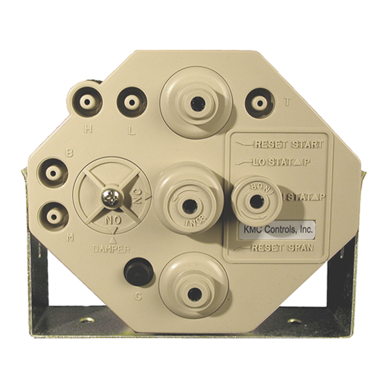
NOT the actuator’s spring range. All adjustments are CCW to increase For adjusting start point and span (upper and lower knobs) review the respective sections All dimensions are in inches (mm). CSC-3000 Series Pneumatic VAV Reset Volume Controllers Applications Guide, Rev G... -
Page 3: Connections
Replace the tubing if it is brittle or to fail. discolored. NOTE: These instructions do not apply to the CSC- 3014 or the CSC-3501/3505. Magnehelic gauge and 0–30 psi gauge in illustration added for checkout and calibration purposes Typical CSC-3011 Application and Connections CSC-3000 Series Pneumatic VAV Reset Volume Controllers Applications Guide, Rev G... -
Page 4: Adjustments And Calibration
Adjusting Minimums and Maximums in a negative reset condition. This means When adjusting the minimum and maximum airflow that when the controller begins to reset at settings, the output responds slowly to changes in the reset start point, it must first overcome the setpoint. Wait for the flow rate to stabilize after the negative adjustment and will not begin making an adjustment (usually 20 to 30 seconds) be- to reset from “0” until a higher thermostat fore making further adjustments. Also, if the damper reset pressure is reached. This negative position is all the way closed or open when starting reset will also reduce the effective range this step, turn the adjustment one full turn, and then of the controller by reducing the low end wait 20 to 30 seconds for a change in the flow read- reset, narrowing the reset span. If a zero ing of the Magnehelic gauge. If no change occurs minimum is required, adjust the LO STAT after this time, repeat until the flow rate changes. ∆P knob until the controller just begins to crack the damper open, and then back-off one-quarter turn and verify zero airflow. (This is typically 2-1/2 knob rotations counterclockwise from the fully clockwise position.) CSC-3000 Series Pneumatic VAV Reset Volume Controllers Applications Guide, Rev G... -
Page 5: Reverse Reset Minimum And Maximum
• 10 psig: CSC-3023 required, adjust the HI STAT ∆P knob until the controller just begins to crack the Thermostat Pressure damper open, then back off slightly and verify zero airflow. NOTE: The reverse reset illustration above assumes no relays are connected between the 6. Repeat Steps 1 through 5 to verify the settings to thermostat and “T” port. be correct and fine tune if necessary. For Reverse Reset (RA thermostat for cooling or DA thermostat for heating), perform the following steps: 1a. On the CSC-3000, disconnect the “T” port and leave it open. Temporarily plug the tubing (but do NOT plug the port). 1b. Alternately, instead of removing the tubing from the T port, (temporarily) remove the plug from the CSC- 3000’s “G” port. 2. Adjust the LO STAT ∆P (center dial) one adjustment at a time until the desired Maximum airflow is read at the Magnehelic gauge and is stable. CSC-3000 Series Pneumatic VAV Reset Volume Controllers Applications Guide, Rev G... -
Page 6: Reset Start Point
(counterclockwise to increase; clockwise to does not typically require adjustment. Leaving this decrease) the reset start point control (at the top adjustment at the factory setting is recommended. of the controller) until the pressure read at “G” If necessary, the reset span can be adjusted (between port is just beginning to move off zero (0) psi. 0 and 10 psi). If the reset span is changed, the NOTE: If the controller does not respond correctly minimum and maximum flows may need to be after all adjustments have been made, it readjusted. may be necessary to correct the reset span To adjust the reset span to another value, perform the adjustment. following steps: 1. Adjust the thermostat to a higher pressure, beyond working range (20 psi is best). 2. Attach a pressure gauge to the “G” port (requires 5/32" O.D. tubing). 3. With a small flat-blade screwdriver, adjust (coun- terclockwise to increase; clockwise to decrease) the reset span control (at the bottom of the con- troller) until pressure at the “G” port equals the desired reset span pressure. CSC-3000 Series Pneumatic VAV Reset Volume Controllers Applications Guide, Rev G... -
Page 7: Troubleshooting
VAV box. from the controller before attempting to blow the sensor clean!) NOTE: The CSC-3000 series are position sensitive. Be sure to mount the controller with • Are reset start and reset span set correctly? See the correct orientation. See Mounting on Reset Start Point on page 6 and Reset Span on page 2. -
Page 8: Magnehelic Gauge To Airflow Rate Chart
Minimum and Maximum adjustments. gauge, follow the line horizontally until it crosses the diagonal inlet size of box. Read straight down from this intersection to determine the flow rate. 150 200 300 400 1000 1500 2000 3000 4000 6000 8000 CFM Flow Rate as read by sensor VAV Airflow Rate by Duct Size CSC-3000 Series Pneumatic VAV Reset Volume Controllers Applications Guide, Rev G... -
Page 9: Replacement Cross-References
*On Trane terminal units, use CSC-3025 instead. **For Honeywell CSP980, the existing velocity pressure flow pickup needs to be replace with KMC SSS-1000 series. ***See KMC CSC Cross-Reference to Universal CSC-3000 Series chart above. All Titus CSC-2000 Series controllers are the same as KMC CSC-2000 Series. -
Page 10: Applications
Applications Cooling DA Thermostat (NO or NC Damper) • LO STAT = Min. Flow • HI STAT = Max. Flow • Reset Range = 8 to 13 psi RA Thermostat (NO or NC Damper) • LO STAT = Max. Flow • HI STAT = Min. Flow (These instructions do not apply to the • Reset Range = 3 to 8 psi CSC-3014 or the CSC-3501/3505.) CSC-3000 Series Pneumatic VAV Reset Volume Controllers Applications Guide, Rev G... -
Page 11: Cooling With Heating Valve
• Spring Range = 3 to 8 psi • LO STAT = Min. Flow • HI STAT = Max. Flow • Reset Range = 8 to 13 psi RA Thermostat, NO or NC Damper, and NC Hot Water Valve • Hot Water Valve = NC • Spring Range = 8 to 13 psi • LO STAT = Max. Flow • HI STAT = Min. Flow • Reset Range = 3 to 8 psi CSC-3000 Series Pneumatic VAV Reset Volume Controllers Applications Guide, Rev G... -
Page 12: Cooling With Heating P-E Switch
RA Thermostat, NO or NC Damper, and NO Heating P-E Switch • Stage 3 On with Decrease • Stage 2 On with Decrease • Stage 3 Off with Increase • Stage 1 On with Decrease • Stage 2 Off with Increase • Stage 1 Off with Increase • LO STAT = Max. Flow • HI STAT = Min. Flow NO PE • Reset Range = 3 to 8 psi Switches CSC-3000 Series Pneumatic VAV Reset Volume Controllers Applications Guide, Rev G... -
Page 13: Dual Duct
Dual Duct Cold Deck CSC-3011-10 • Damper = NC • LO STAT = Min. Flow • HI STAT = Max. Flow • Reset = 8 to 13 psi Hot Deck CSC-3021-10* • Damper = NO • LO STAT = Max. Flow • HI STAT = Min. Flow • Reset = 3 to 8 psi *Or use a CSC-3011-10 and change the reset from 8 to 3. See Reset Start Point on page CSC-3000 Series Pneumatic VAV Reset Volume Controllers Applications Guide, Rev G... -
Page 14: Dual Duct, Constant Volume
Dual Duct, Constant Volume Cold Deck/Common Discharge CSC-3011-10 • Damper = NC • LO STAT = Constant Volume Flow • Reset = 8 to 13 psi Hot Deck CSC-3011-10 • Damper = NO • LO STAT = Min. Flow • HI STAT = Max. Flow • Reset = 13 to 8 psi CSC-3000 Series Pneumatic VAV Reset Volume Controllers Applications Guide, Rev G... -
Page 15: Index
Reset, Types Direct Reset Reverse Reset Dual Duct Dual Duct, Constant Volume Troubleshooting G Port KMC Controls, Inc. 19476 Industrial Drive New Paris, IN 46553 574.831.5250 www.kmccontrols.com info@kmccontrols.com CSC-3000 Series Pneumatic VAV Reset Volume Controllers © 2013 KMC Controls, Inc. Applications Guide, Rev G AN-1205B-RevG...
Need help?
Do you have a question about the CSC-3000 Series and is the answer not in the manual?
Questions and answers