Advertisement
Quick Links
Application Guide
Overview ............................................................... 1
Important Notices ................................................. 1
CSC-1001 Function ............................................... 1
Sample Applications .............................................. 2
Replacement by CSC-2001/2003 ........................... 3
Replacement by CSC-3011 .................................... 3
Overview
CSC-1001 Constant Volume Controllers have been
discontinued. However, they can be replaced with a
CSC-2001/2003/3011 controller and (for VAV applica-
tions) an RCC-1008/1108 relay.
For more information about a particular device, see
the respective device data sheet, installation guide,
and/or application guide.
Important Notices
The material in this document is for information
purposes only. The contents and the product it
describes are subject to change without notice. KMC
Controls, Inc. makes no representations or warran-
ties with respect to this document. In no event shall
KMC Controls, Inc. be liable for any damages, direct
or incidental, arising out of or related to the use of
this document.
Replacing CSC-1001 with CSC-2000/3000 Series Controllers
Replacing CSC-1001 Controllers
with CSC-2000/3000 Series Controllers
CSC-1001
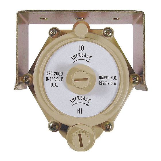
CSC-1001 Function
The CSC-1001 is designed for use with normally
open dampers in either of the following applications:
• Constant air volume (CAV) terminals
• Variable air volume (VAV) terminals with maxi-
mum flow limiting
CAV operation is configured by connecting a nor-
mally open actuator to the C port on the controller
(or the H port if the T port is open) and adjusting the
setpoint screw to the desired flow setpoint. Airflow
is measured by an SSS-1000 series sensor connected
between the HI and LO ports. Adjusting the setpoint
screw clockwise will increase the flow setpoint;
adjusting the screw counter-clockwise will decrease
the flow setpoint. The T port may be exhausted to
atmosphere during constant volume operation.
When used in VAV applications where a high flow
limit is necessary, the controller should have a
normally open damper connected to the H port, a
reverse acting thermostat connected to the T port,
and an SSS-1000 series flow pickup between HI and
LO. The C port should be capped (as installed from
the factory). With the T port exhausted, or at a low
pressure, the setpoint screw can be adjusted for the
maximum flow limit. The controller will supply the
H port with the higher of either the thermostat signal
or the configured maximum flow limit pressure, thus
limiting the maximum airflow once the thermostat
signal falls below the maximum flow setpoint.
1
CSC-3011
Application Guide, AN0811A Rev. A
Advertisement

Related Manuals for KMC Controls CSC-2000 Series


Summary of Contents for KMC Controls CSC-2000 Series
- Page 1 In no event shall limit is necessary, the controller should have a KMC Controls, Inc. be liable for any damages, direct normally open damper connected to the H port, a or incidental, arising out of or related to the use of reverse acting thermostat connected to the T port, this document.
- Page 2 Sample Applications Constant Volume Application Actuator CSC-2001/2003 CSC-3011 Reset Volume Reset Volume SSS-1000 Series Controller Controller Airflow Sensor Actuator Constant Volume Airflow adjusted using DAMPER the LO Adjustment Knob (center knob) VAV Application with a High Flow Limit Thermostat SSS-1000 Series RA Cool Airflow Sensor Actuator...
- Page 3 Replacement by CSC-2001/2003 Replacement by CSC-3011 CSC-2000 Series Reset Volume Controllers may be A CSC-3011 “universal” Reset Volume Controller used to obtain the same functionality of CSC-1001 may also be used to obtain the same functionality of Constant Volume Controllers. For constant volume CSC-1001 Constant Volume Controllers.
Need help?
Do you have a question about the CSC-2000 Series and is the answer not in the manual?
Questions and answers