
Related Manuals for KMC Controls BAC-4000 series


Summary of Contents for KMC Controls BAC-4000 series
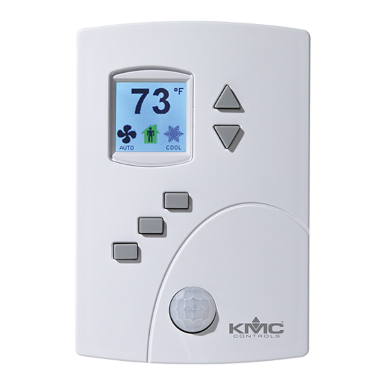
- Page 1 Installation, Operation, and Application Guide AppStat™ BAC-4000 series controllers for Fan Coil Units, Roof Top Units, and Heat Pump Units. Revision G...
- Page 2 KMC Controls, Inc. makes no representations or warranties with respect to this manual. In no event shall KMC Controls, Inc. be liable for any damages, direct or incidental, arising out of or related to the use of this manual.
-
Page 3: Table Of Contents
Installation, Operation, and Application Guide for AppStat Contents C o n t e n t s Contents Section 1: Introduction to the AppStat Specifications Installation accessories AppStat model numbers Safety considerations Section 2: Installing the AppStat Planning for motion sensing Mounting the AppStat Rough-in preparation Installing the AppStat... - Page 4 Contents KMC Controls, Inc. Advanced options Section 5: Sequences of operation Room temperature setpoints Types of setpoints Setpoint limits Occupancy, motion sensing, and standby Automatic cooling and heating changeover Scheduling occupancy Dehumidification sequence Fan status Display blanking and backlight Temperature sensing inputs...
- Page 5 Installation, Operation, and Application Guide for AppStat Contents Fan Coil Unit—Two-pipe with three-speed fan and on/off valves Fan Coil Unit—Two-pipe with three-speed fan and modulating valve Fan Coil Unit—Two-pipe with modulating fan and on/off valve Fan Coil Unit—Two-pipe with modulating fan and modulating valve Fan Coil Unit—Two-pipe with three-speed fan, modulating valve, and electric heat Fan Coil Unit—Two-pipe with modulating speed fan, modulating valve, and electric heat Roof Top Unit applications...
- Page 6 Contents KMC Controls, Inc. Revision G...
- Page 7 KMC Controls, Inc.. It also introduces safety information. Review this material before installing or operating the controllers. The BAC-4000 series of controllers are space mounted devices that combine a BACnet controller with temperature, humidity and motion sensors. The controllers include programs for the following applications.
-
Page 8: Section 1: Introduction To The Appstat
Section 1: Introduction to the AppStat KMC Controls, Inc. Specifications AppStat specifications are subject to change without notice. User Interface The user interface is a color display and with five push buttons. Through the menu driven display, an operator can do the following. - Page 9 Installation, Operation, and Application Guide for AppStat Section 1: Introduction to the AppStat Short-circuit protected Loads up to 10 mA at 0–12 volts DC 8-bit PWM digital-to-analog conversion Relay outputs Relay outputs are configured to represent BACnet binary objects. The outputs control on/off valves, speeds for three-speed fans, fan start circuits, or other equipment that requires an on or off input signal.
- Page 10 Section 1: Introduction to the AppStat KMC Controls, Inc. Humidity Sensor Type CMOS Humidity 0 to 100% RH Accuracy at 25° C ± 2% RH from 10 to 90% RH Response time 4 seconds or less Regulatory UL 916 Energy Management Equipment...
- Page 11 Installation, Operation, and Application Guide for AppStat Section 1: Introduction to the AppStat Dimensions Table 1–1 AppStat Dimensions 3.50 in. 5.12 in. 1.12 in. 89 mm 130 mm 29 mm Motion sensor Motion sensors are options available only on select models. Detector type Passive infrared Range...
-
Page 12: Installation Accessories
10 m 10 m 32.8 ft 32.8 ft Top view Side view Installation The following accessories are available from KMC Controls, Inc. accessories XEE-6111-040 Single-hub 120 volt power transformer XEE-6112-040 Dual-hub 120 volt power transformer XEE-6311-075 120/240/277/480VAC, 24 VAC, 75 VA transformer... -
Page 13: Appstat Model Numbers
Installation, Operation, and Application Guide for AppStat Section 1: Introduction to the AppStat AppStat model Use the following charts to identify features in a specific AppStat model. numbers Fan coil units —The model numbers for these controllers end with "0001". The inputs, outputs, and sequences of operation are configured and programmed for the following functions. - Page 14 Section 1: Introduction to the AppStat KMC Controls, Inc. Roof top units —The model numbers for these controllers end with "0002". These models control roof top or similar packaged or split unitary units. The inputs, outputs, and sequences of operation are configured and programmed for the following functions.
- Page 15 Installation, Operation, and Application Guide for AppStat Section 1: Introduction to the AppStat See the following chart for the specific features included with each model. Illustration 1–3 Model numbers for heat pump units BAC-4 _ _ _ CW0003 1 3H/2C 3 3H/2C and economizer 0 Without humidity 2 With humidity...
-
Page 16: Safety Considerations
Section 1: Introduction to the AppStat KMC Controls, Inc. Safety KMC Controls, Inc. assumes the responsibility for providing you a safe product and safety guidelines during its use. Safety means protection to all considerations individuals who install, operate, and service the equipment as well as protection of the equipment itself. -
Page 17: Section 2: Installing The Appstat
Installation, Operation, and Application Guide for AppStat Se c t i o n 2: I n s t al l i n g t h e A p p St at This section provides important instructions and guidelines for installing the AppStat. -
Page 18: Mounting The Appstat
Section 2: Installing the AppStat KMC Controls, Inc. The effective detection range is approximately 10 meters or 33 feet. Factors that may reduce the range include: The difference between the surface temperature of the object and the background temperature of the room is too small. -
Page 19: Rough-In Preparation
Installation, Operation, and Application Guide for AppStat Section 2: Installing the AppStat Rough-in preparation Complete rough-in wiring at each location before mounting an AppStat. This includes the following steps. Install the supplied mounting base directly to a wall, a vertical electrical box, or a box with a wall plate kit. -
Page 20: Connecting Inputs
Section 2: Installing the AppStat KMC Controls, Inc. 4. Position the base with the embossed UP toward the ceiling and fasten it directly to a vertical 2 x 4 inch electrical box. For horizontal boxes or Installation accessories on page 4 x 4 applications, use a wall plate kit. See for part numbers. -
Page 21: Discharge Air Temperature Sensor
Installation, Operation, and Application Guide for AppStat Section 2: Installing the AppStat Illustration 2–3 Wiring for remote space temperature sensor 24VAC FAN-L FAN-M STE-6011W10 FAN-H or equivalent –A Discharge air temperature sensor Connect a 10kΩ, Type III thermistor temperature probe to the discharge air temperature (DAT) input. -
Page 22: Water Temperature Sensor
Section 2: Installing the AppStat KMC Controls, Inc. suitable for this application. Follow the instructions supplied with the switch for installation. Illustration 2–5 Wiring for a fan status switch 24VAC N.C Fan Status FAN-L CSE-1102 FAN-M FAN-H –A Water temperature sensor Connect a 10kΩ, Type III thermistor temperature probe to the water... -
Page 23: Outside Air Temperature
Installation, Operation, and Application Guide for AppStat Section 2: Installing the AppStat Illustration 2–6 Wiring for a water temperature sensor 24VAC FAN-L STE-1455 or FAN-M equivalent FAN-H –A Outside air temperature Connect a 10kΩ, Type III thermistor temperature probe to the outside air temperature (OAT) input. -
Page 24: Connecting Outputs
Section 2: Installing the AppStat KMC Controls, Inc. Connecting outputs The AppStat outputs are model dependent and are configured for specific applications. No field programming or set up is required or possible. Depending on model and application, the AppStat outputs are designed for either 24 volt AC or 0-10 volt DC loads. -
Page 25: Connecting To A Modulating Fan
Installation, Operation, and Application Guide for AppStat Section 2: Installing the AppStat Illustration 2–8 Connections to a three-speed fan 24 VAC 24VAC FAN-L FAN-M FAN-H –A Connecting to a modulating fan The following diagram shows the connections for a modulating speed fan. The fan start circuit must be a 24-volt AC circuit. -
Page 26: Connecting On/Off Valves
Section 2: Installing the AppStat KMC Controls, Inc. Illustration 2–9 Connections for a modulating fan 24 VAC 24VAC FAN-L FAN-M FAN-H –A Connecting on/off valves The following diagram shows the connections on/off valves. The valves are activated by 24-volts AC. -
Page 27: Connecting To Modulating Valves
Installation, Operation, and Application Guide for AppStat Section 2: Installing the AppStat Connecting to modulating valves The following diagram shows the connections for a modulating mixing valves. The valve control signal is a 0-10 volt analog output. Illustration 2–11 Modulating heating and cooling valves 24 VAC Cooling Heating... -
Page 28: Connecting An Economizer
The AppStat requires an external, 24 volt, AC power source. Use the following guidelines when choosing and wiring transformers. Use only a Class-2 transformer of the appropriate size to supply power. KMC Controls recommends powering the AppStat from a dedicated controls transformer. Connect the transformer’s neutral lead to the COM terminal. -
Page 29: Maintenance
Installation, Operation, and Application Guide for AppStat Section 2: Installing the AppStat Illustration 2–13 Wiring for AppStat power Controls transformer 24VAC FAN-L 24 VAC FAN-M Class-2 FAN-H –A Maintenance Remove dust as necessary from the holes in the top and bottom. Clean the display with soft, damp cloth and mild soap. - Page 30 Section 2: Installing the AppStat KMC Controls, Inc. Revision G...
-
Page 31: Section 3: User Functions
Installation, Operation, and Application Guide for AppStat Se c t i o n 3: U s e r f u n c t i o n s This section covers topics for the end user in a facility. AppStat user functions are limited to changing the following functions. Active temperature setpoints Fan operation Changing between heating and cooling... - Page 32 Section 3: User functions KMC Controls, Inc. The three buttons below the display are defined by labels in the soft key bar. Typically the buttons are designated for the following functions. Back—Returns to the previous menu. Cncl—Cancels current changes. Done—Push this button at any point while entering a value. For example,...
- Page 33 Installation, Operation, and Application Guide for AppStat Section 3: User functions Operating mode icons (continued) Icon Description Mode Heating—The system will heat the Heating/Cooling space until the heating setpoint is reached. The icon is in motion when heating is taking place. System is off Heating/Cooling Dehumidification—During...
-
Page 34: Entering A User Password
Section 3: User functions KMC Controls, Inc. Entering a user User functions may require a password consisting of four numbers. Once a user password is entered it will remain active for 60-seconds after the last password button is pushed. Enter a user password... -
Page 35: Changing The Active Setpoints
Installation, Operation, and Application Guide for AppStat Section 3: User functions Changing the active To enter or change the active temperature setpoints you may need user password. To enter the password, see Entering a user password on page 34 setpoints Note: In the following procedure the current active setpoint–either cooling or heating–is the first setpoint to change. -
Page 36: Setting The Operating Modes
Section 3: User functions KMC Controls, Inc. Setting the The operating modes set the following functions. operating modes Fan operation Changing between heating and cooling Override scheduled occupancy or occupancy that has been set by a schedule. Change the display units from Fahrenheit to Celsius. - Page 37 Installation, Operation, and Application Guide for AppStat Section 3: User functions Set the operating modes (continued) Procedure Steps Display 1. Push the button under the fan icon. Set the fan mode. Note: If a user password has previously been Fan icon entered or if the AppStat has not been set up with a user password, entering a password is not required.
- Page 38 Section 3: User functions KMC Controls, Inc. Set the operating modes (continued) Procedure Steps Display Entering an override setpoint can only take Change the override ° place if the AppStat is in the unoccupied mode. setpoint 1. Push the button under the unoccupied icon...
-
Page 39: Section 4: Commissioning Functions
Installation, Operation, and Application Guide for AppStat Se c t i o n 4: C o m m i s s i o n i n g f u n c t i o n s This topics in this section are advanced topics for control technicians and engineers. -
Page 40: Enter The Commissioning Mode
Section 4: Commissioning functions KMC Controls, Inc. Enter the For access to the commissioning functions you will need to know Password 2. commissioning If the controller has not been previously set up, no password is required. mode A new Password 2 can be entered in the advanced commissioning functions. -
Page 41: Setting The Commissioning Setpoints
Installation, Operation, and Application Guide for AppStat Section 4: Commissioning functions Setting the The commissioning setpoints set the operational setpoints and limits for the AppStat. The functions of the setpoints and how they are used are describe in commissioning Room temperature setpoints on page 66 the topic . - Page 42 Section 4: Commissioning functions KMC Controls, Inc. Procedure to set the commissioning setpoints (continued) Procedure Steps Display SETPOINT OCC COOL—The cooling setpoint that is OCC COOL used as the active setpoint when the system OCC HEAT UNOCC COOL is occupied.
-
Page 43: Set Up Communications
Installation, Operation, and Application Guide for AppStat Section 4: Commissioning functions Set up Setting BACnet communications properties is required only if the AppStat is integrated into a network with other BACnet controllers. Entering the communications communications properties requires entering Password 2 which is described in the topic Enter the commissioning mode on page 40 Connecting to an MS/TP network on page 121... - Page 44 Section 4: Commissioning functions KMC Controls, Inc. Set BACnet communication properties (continued) Procedure Steps Display MAC: Enter Enter Done BAUD: 76800 38400 19200 9600 Auto Cncl Enter Done Revision G...
-
Page 45: Set The Time And Date
Installation, Operation, and Application Guide for AppStat Section 4: Commissioning functions Set the time and Setting the time and date requires entering Password 2 which is described in the topic Enter the commissioning mode on page 40 date Note: If the AppStat is connected to a BACnet network that includes a time service master, the time and date are automatically set to the network time and date. - Page 46 Section 4: Commissioning functions KMC Controls, Inc. Set the time and date (continued) Procedure Steps Display Choose one of the features in the SET CLOCK SET CLOCK Choose a clock DATE TIME menu to change the date, time, or Daylight function to set.
-
Page 47: Setting The Occupancy Schedule
Installation, Operation, and Application Guide for AppStat Section 4: Commissioning functions Setting the The schedule in the AppStat controls the occupancy mode. If the schedule is set to ON, the AppStat uses the occupied setpoint as the active setpoint. If the occupancy schedule schedule is OFF, the unoccupied setpoint is used. - Page 48 Section 4: Commissioning functions KMC Controls, Inc. Set up schedules (continued) Procedure Steps Display 1. From the SCHEDULE menu, choose one of SCHEDULE Choose and set a SET CLOCK the following schedule entry methods to weekly schedule. SETPOINT HOLD ENTIRE WEEK enter a weekly schedule.
- Page 49 Installation, Operation, and Application Guide for AppStat Section 4: Commissioning functions Set up schedules (continued) Procedure Steps Display Use a holiday schedule to override the values in HOLIDAYS Choose and set a HOL1 the weekly schedule. Months and years can be holiday schedule HOL2 HOL3...
-
Page 50: Set Fan Coil Unit System Options
Section 4: Commissioning functions KMC Controls, Inc. Set fan coil unit The items in the system menu control application specific functions for fan coil units. Entering the system options requires entering Password 2 which is system options Enter the commissioning mode on page 40... - Page 51 Installation, Operation, and Application Guide for AppStat Section 4: Commissioning functions Set up fan coil unit system options (continued) Procedure Steps Display Set the fan delay. From the SYSTEM menu choose FAN DELAY FAN OFF DELAY 2 2 mins OFF to set the time the system fan will continue to run after the last heating or cooling stage is turned off.
- Page 52 Section 4: Commissioning functions KMC Controls, Inc. Set up fan coil unit system options (continued) Procedure Steps Display Select FAN MINIMUM or FAN MAXIMUM Set fan speeds for FAN MINIMUM: from the SYSTEM menu to set fan speed for 35 %utoz modulating speed modulation fans.
-
Page 53: Set Roof Top Unit System Options
Installation, Operation, and Application Guide for AppStat Section 4: Commissioning functions Set roof top unit The items in the system menu control application specific functions for roof top units. Entering the system options requires entering Password 2 which is system options Enter the commissioning mode on page 40 described in the topic Set up roof top unit system options... - Page 54 Section 4: Commissioning functions KMC Controls, Inc. Set up roof top unit system options (continued) Procedure Steps Display Set the fan delay. From the SYSTEM menu choose FAN OFF FAN OFF DELAY 2 2 mins DELAY to set the time the system fan will continue to run after the last heating or cooling stage is turned off.
- Page 55 Installation, Operation, and Application Guide for AppStat Section 4: Commissioning functions Set up roof top unit system options (continued) Procedure Steps Display The economizer feature is an option and not Enable the ECON ENABLE: available on all models. ENABLED economizer. DISABLED (Optional feature) To set up the economizer do the following:...
-
Page 56: Set Heat Pump Unit System Options
Section 4: Commissioning functions KMC Controls, Inc. Set heat pump unit The items in the system menu control application specific functions for heat pump units. Entering the system options requires entering Password 2 which system options Enter the commissioning mode on page 40... - Page 57 Installation, Operation, and Application Guide for AppStat Section 4: Commissioning functions Set up heat pump unit system options (continued) Procedure Steps Display Set the local override From the SYSTEM menu choose LOCAL OVRD LOCAL OVRD TIME 2 60 mins time. TIME to set the time the AppStat will hold an override temperature setpoint as the active setpoint.
- Page 58 Section 4: Commissioning functions KMC Controls, Inc. Set up heat pump unit system options (continued) Procedure Steps Display The economizer feature is an option and not Enable the ECON ENABLE: available on all models. ENABLED economizer. DISABLED (Optional feature) To set up the economizer do the following: 1.
- Page 59 Installation, Operation, and Application Guide for AppStat Section 4: Commissioning functions Set up heat pump unit system options (continued) Procedure Steps Display Set the lockout From the SYSTEM menu choose AUX HT AUX HT LOCKOUT: 60 °F temperature for LOCKOUT to set the minimum outside air temperature for auxiliary heat lockout.
-
Page 60: Advanced Options
Section 4: Commissioning functions KMC Controls, Inc. Advanced options Use the advanced options to set up the following items. Choosing an application and units of measure. Adjusting the PID loops Changing passwords Calibrating inputs Setting the display blanking Modifying access to users with Password 1. - Page 61 Installation, Operation, and Application Guide for AppStat Section 4: Commissioning functions Choosing advance options (continued) Procedure Steps Display Choose RESTORE APP from the ADVANCED RESTORE APP Reset the 2P FCU-METRIC menu to reset the AppStat to the original application and 4P FCU-METRIC 2P FCU-ENGLISH configuration and settings.
- Page 62 Section 4: Commissioning functions KMC Controls, Inc. Choosing advance options (continued) Procedure Steps Display Choose PASSWORDS from the ADVANCED PASSWORDS Enter or change PASSWORD1 menu to set either Password 1 or Password 2. passwords. PASSWORD2 Password 1 is for a facility user and limits changes to active setpoints, fan operation, occupancy, and heating and cooling modes.
- Page 63 Installation, Operation, and Application Guide for AppStat Section 4: Commissioning functions Choosing advance options (continued) Procedure Steps Display Choose DISPLAY from the ADVANCED menu to DISPLAY Set the display BLANKING set the display appearance after the last button is blanking. DIM LEVEL pushed.
- Page 64 Section 4: Commissioning functions KMC Controls, Inc. Revision G...
-
Page 65: Section 5: Sequences Of Operation
Installation, Operation, and Application Guide for AppStat Se c t i o n 5: Se q u e n c e s o f o p e r at i o n Topics in this section cover the sequences of operation for the AppStat. These are advanced topics for control's technicians and engineers. -
Page 66: Room Temperature Setpoints
Section 5: Sequences of operation KMC Controls, Inc. Room temperature There are four temperature setpoints each for heating and cooling for a total of eight setpoints. setpoints Active cooling Occupied cooling Unoccupied cooling Standby cooling Active heating Occupied heating Unoccupied heating... -
Page 67: Setpoint Limits
Installation, Operation, and Application Guide for AppStat Section 5: Sequences of operation Setpoint limits The programming in the AppStat will limit the setpoint entry so that no heating setpoint is set higher than its corresponding cooling setpoint. If a user is adjusting a setpoint and it falls within the range set by the value of Minimum Setpoint Differential, the corresponding setpoint will be changed to maintain the differential. -
Page 68: Automatic Cooling And Heating Changeover
Section 5: Sequences of operation KMC Controls, Inc. Automatic cooling The AppStat can be set to automatically change between the heating and cooling modes. and heating changeover If the space temperature rises above the active cooling setpoint, the mode is set to cooling. -
Page 69: Display Blanking And Backlight
Installation, Operation, and Application Guide for AppStat Section 5: Sequences of operation BACnet priority 5. The fan output remains enabled until the fan status switch Value opens. The state of fan status is stored in a binary variable. See the topic objects on page 117 for variable object details. -
Page 70: Discharge Air Temperature Sensor
Section 5: Sequences of operation KMC Controls, Inc. Input objects on page 114 stored in an analog value object. See the topics Value objects on page 117 for object details. Discharge air temperature sensor The Discharge Air Temperature (DAT) input is a required input for economizer applications and is an option for other applications. -
Page 71: Modulating Valves
Installation, Operation, and Application Guide for AppStat Section 5: Sequences of operation fallen to 5%. The controller programming supports both normal and reverse action valves which can be set from the user interface. Normal—The valve is closed when the output is inactive and open when the output is active. -
Page 72: Electric Heat For Fan Coil Units
Section 5: Sequences of operation KMC Controls, Inc. Electric heat for fan For AppStat fan coil models that support both on/off and modulating valves, electric heat can be added to two-pipe systems. Typically this heat is a duct or coil units baseboard resistance heater controlled by a relay. -
Page 73: Automatic Fan Control
Installation, Operation, and Application Guide for AppStat Section 5: Sequences of operation Set fan coil unit system user interface during system setup. See the topic options on page 50 Automatic fan control A user with Password 1 can set the AppStat controlled fan to either run continuously or to start automatically on a call for cooling or heating. -
Page 74: Staged Heating And Cooling For For Roof Top And Heat Pump Units
Section 5: Sequences of operation KMC Controls, Inc. Staged heating and Staged heating and cooling is used for applications other than chilled or hot water systems. Typically the AppStat controls gas heat, electric heat, or direct cooling for for roof expansion (DX) cooling with staged heating and cooling. -
Page 75: Economizer Cooling For Roof Top And Heat Pump Units
Installation, Operation, and Application Guide for AppStat Section 5: Sequences of operation Economizer cooling Some models of the AppStat include programming for an economizer. This programing controls an economizer outside air damper connected to the for roof top and output terminal (ECON). heat pump units Note: The optional economizer can be enabled only if outside air temperature and... - Page 76 Section 5: Sequences of operation KMC Controls, Inc. None —This function is a manual operation that can only be turned on from the user interface. When emergency heat is turned on, the AUX/E output is used to maintain the active heating setpoint and both compressor outputs are locked-out.
-
Page 77: Section 6: Application Drawings
Installation, Operation, and Application Guide for AppStat Se c t i o n 6: A p p l i c at i o n d r aw i n g s This section covers the drawings, materials, and instructions for specific AppStat applications. -
Page 78: Fan Coil Unit Applications
Section 6: Application drawings KMC Controls, Inc. Fan Coil Unit This section covers applications for fan coil units. For other applications see Roof Top Unit applications on page 98 Heat Pump Unit applications on page applications Fan Coil Unit—Four-pipe with three-speed fan and on/off valves This application applies to models BAC-4001CW0001, BAC-4021CW0001, BAC-4201CW0001, and BAC-4221CW0001. - Page 79 Installation, Operation, and Application Guide for AppStat Section 6: Application drawings Illustration 6–1 Wiring details: Four-pipe FCU with on/off valves FST N.C Fan Status STE-1405 CSE-1102 Controls transformer 24VAC FAN-L 24 VAC STE-6011W10 FAN-M Class-2 or equivalent FAN-H (optional) –A Revision G...
-
Page 80: Fan Coil Unit-Four-Pipe With Three-Speed Fan And Modulating Valves
Section 6: Application drawings KMC Controls, Inc. Fan Coil Unit—Four-pipe with three-speed fan and modulating valves This application applies to models BAC-4002CW0001, BAC-4022CW0001, BAC-4202CW0001, and BAC-4222CW0001. Fan status switch (FST) and discharge air temperature sensor (DAT) are optional. They are typically used only when the AppStat is connected to a network. - Page 81 Installation, Operation, and Application Guide for AppStat Section 6: Application drawings Illustration 6–2 Wiring details: Four pipe FCU with three-speed fan and modulating valves N.C Fan Status STE-1405 CSE-1102 0-10 0-10 Controls transformer 24VAC FAN-L 24 VAC STE-6011W10 FAN-M Class-2 or equivalent FAN-H (optional)
-
Page 82: Fan Coil Unit-Four-Pipe With Modulating Fan And On/Off Valves
Section 6: Application drawings KMC Controls, Inc. Fan Coil Unit—Four-pipe with modulating fan and on/off valves This application applies to models BAC-4007CW0001, BAC-4027CW0001, BAC-4207CW0001, and BAC-4227CW0001. Fan status switch (FST) and discharge air temperature sensor (DAT) are optional. They are typically used only when the AppStat is connected to a network. - Page 83 Installation, Operation, and Application Guide for AppStat Section 6: Application drawings Illustration 6–3 Wiring details: Four-pipe FCU with modulating fan and on/off valves N.C Fan Status STE-1405 SPD SRT CSE-1102 Controls transformer 24VAC FAN-L 24 VAC STE-6011W10 FAN-M Class-2 or equivalent FAN-H (optional) –A...
-
Page 84: Fan Coil Unit-Four-Pipe With Modulating Fan And Modulating Valves
Section 6: Application drawings KMC Controls, Inc. Fan Coil Unit—Four-pipe with modulating fan and modulating valves This application applies to models BAC-4008CW0001, BAC-4028CW0001, BAC-4208CW0001, and BAC-4228CW0001. Fan status switch (FST) and discharge air temperature sensor (DAT) are optional. They are typically used only when the AppStat is connected to a network. - Page 85 Installation, Operation, and Application Guide for AppStat Section 6: Application drawings Illustration 6–4 Wiring details: Four-pipe FCU with modulating fan and modulating valves N.C Fan Status STE-1405 SPD SRT CSE-1102 0-10 0-10 Controls transformer 24VAC FAN-L 24 VAC STE-6011W10 FAN-M Class-2 or equivalent FAN-H...
-
Page 86: Fan Coil Unit-Two-Pipe With Three-Speed Fan And On/Off Valves
Section 6: Application drawings KMC Controls, Inc. Fan Coil Unit—Two-pipe with three-speed fan and on/off valves This application applies to models BAC-4001CW0001, BAC-4201CW0001, BAC-4021CW0001, and BAC-4221CW0001. The water temperature sensor (WST) is required for two-pipe units. Fan status switch (FST) and discharge air temperature sensor (DAT) are optional. - Page 87 Installation, Operation, and Application Guide for AppStat Section 6: Application drawings Illustration 6–5 Wiring details: Two-pipe FCU with three-speed fan and on/off valves FST N.C Fan Status STE-1405 CSE-1102 STE-1455 Controls transformer 24VAC FAN-L 24 VAC STE-6011W10 Class-2 FAN-M or equivalent FAN-H (optional) –A...
-
Page 88: Fan Coil Unit-Two-Pipe With Three-Speed Fan And Modulating Valve
Section 6: Application drawings KMC Controls, Inc. Fan Coil Unit—Two-pipe with three-speed fan and modulating valve This application applies to models BAC-4002CW0001, BAC-4022CW0001, BAC-4202CW0001, and BAC-4222CW0001. The water temperature sensor (WST) is required for two-pipe units. Fan status switch (FST) and discharge air temperature sensor (DAT) are optional. - Page 89 Installation, Operation, and Application Guide for AppStat Section 6: Application drawings Illustration 6–6 Wiring details: Two-pipe FCU with three-speed fan and modulating valve FST N.C Fan Status STE-1405 CSE-1102 0-10 STE-1455 Controls transformer 24VAC FAN-L 24 VAC STE-6011W10 Class-2 FAN-M or equivalent FAN-H (optional)
-
Page 90: Fan Coil Unit-Two-Pipe With Modulating Fan And On/Off Valve
Section 6: Application drawings KMC Controls, Inc. Fan Coil Unit—Two-pipe with modulating fan and on/off valve This application applies to models BAC-4007CW0001, BAC-4027CW0001, BAC-4207CW0001, and BAC-4227CW0001. The water temperature sensor (WST) is required for two-pipe units. Fan status switch (FST) and discharge air temperature sensor (DAT) are optional. - Page 91 Installation, Operation, and Application Guide for AppStat Section 6: Application drawings Illustration 6–7 Wiring details: Two-pipe FCU with modulating fan and on/off valve N.C Fan Status STE-1405 SPD SRT CSE-1102 STE-1455 Controls transformer 24VAC FAN-L 24 VAC STE-6011W10 FAN-M Class-2 or equivalent FAN-H (optional)
-
Page 92: Fan Coil Unit-Two-Pipe With Modulating Fan And Modulating Valve
Section 6: Application drawings KMC Controls, Inc. Fan Coil Unit—Two-pipe with modulating fan and modulating valve This application applies to models BAC-4008CW0001, BAC-4028CW0001, BAC-4208CW0001, and BAC-4228CW0001. The water temperature sensor (WST) is required for two-pipe units. Fan status switch (FST) and discharge air temperature sensor (DAT) are optional. - Page 93 Installation, Operation, and Application Guide for AppStat Section 6: Application drawings Illustration 6–8 Wiring details: Two-pipe FCU with modulating fan and modulating valve STE-1405 SPD SRT N.C Fan Status CSE-1102 0-10 STE-1455 Controls transformer 24VAC FAN-L 24 VAC STE-6011W10 Class-2 FAN-M or equivalent FAN-H...
-
Page 94: Fan Coil Unit-Two-Pipe With Three-Speed Fan, Modulating Valve, And Electric Heat
Section 6: Application drawings KMC Controls, Inc. Fan Coil Unit—Two-pipe with three-speed fan, modulating valve, and electric heat This application applies to models BAC-4003CW0001, BAC-4023CW0001, BAC-4203CW0001, and BAC-4223CW0001. The water temperature sensor (WST) is required for two-pipe units. Fan status switch (FST) and discharge air temperature sensor (DAT) are optional. - Page 95 Installation, Operation, and Application Guide for AppStat Section 6: Application drawings Illustration 6–9 Wiring details: Two-pipe FCU with three-speed fan, modulating valve, and electric heat FST N.C Fan Status 24 VAC CSE-1102 STE-1405 Relay 0-10 STE-1455 Controls transformer 24VAC FAN-L 24 VAC STE-6011W10 FAN-M...
-
Page 96: Fan Coil Unit-Two-Pipe With Modulating Speed Fan, Modulating Valve, And Electric Heat
Section 6: Application drawings KMC Controls, Inc. Fan Coil Unit—Two-pipe with modulating speed fan, modulating valve, and electric heat This application applies to models BAC-4003CW0001, BAC-4023CW0001, BAC-4203CW0001, and BAC-4223CW0001. The water temperature sensor (WST) is required for two-pipe units. Fan status switch (FST) and discharge air temperature sensor (DAT) are optional. - Page 97 Installation, Operation, and Application Guide for AppStat Section 6: Application drawings Illustration 6–10 Wiring details: Two-pipe FCU with modulating fan, modulating valve, and electric heat FST N.C Fan Status SPD SRT 24 VAC CSE-1102 STE-1405 Relay 0-10 STE-1455 Controls transformer 24VAC FAN-L 24 VAC...
-
Page 98: Roof Top Unit Applications
Section 6: Application drawings KMC Controls, Inc. Roof Top Unit This section covers applications for roof top units. For other applications see Fan Coil Unit applications on page 78 Heat Pump Unit applications on applications page 108 Roof Top Unit—Two-stage gas heat and two-stage DX cooling This application applies to models BAC-4221CW0002, BAC-4021CW0002, BAC-4201CW0002, and BAC-4001CW0002. - Page 99 Installation, Operation, and Application Guide for AppStat Section 6: Application drawings Illustration 6–11 Wiring details: RTU two-stage gas heat and two-stage DX cooling DX DX N.C Fan Status STE-1405 W2 W1 Y2 Y1 CSE-1102 STE-1451 Controls transformer 24VAC 24 VAC STE-6011W10 Class-2 or equivalent...
-
Page 100: Roof Top Unit-Two-Stage Gas Heat And Two-Stage Dx Cooling With Economizer
Section 6: Application drawings KMC Controls, Inc. Roof Top Unit—Two-stage gas heat and two-stage DX cooling with economizer This application applies to models BAC-4223CW0002, BAC-4023CW0002, BAC-4203CW0002, and BAC-4003CW0002 Fan status switch (FST) is optional. Typically it is used only when the AppStat is connected to a network. - Page 101 Installation, Operation, and Application Guide for AppStat Section 6: Application drawings Illustration 6–12 Wiring details: RTU two-stage gas heat and two-stage DX cooling and economizer DX DX N.C Fan Status STE-1405 W2 W1 Y2 Y1 CSE-1102 0-10 STE-1451 Controls transformer 24VAC 24 VAC Class-2...
-
Page 102: Roof Top Unit-Cooling And Heating With Modulating Valves And Economizer
Section 6: Application drawings KMC Controls, Inc. Roof top unit—Cooling and heating with modulating valves and economizer This application applies to models BAC-4003CW0002, BAC-4023CW0002, BAC-4203CW0002, and BAC-4223CW0002. Fan status switch (FST) is optional. Typically it is used only when the AppStat is connected to a network. - Page 103 Installation, Operation, and Application Guide for AppStat Section 6: Application drawings Illustration 6–13 Wiring details: RTU with modulating valves for cooling and heating and economizer N.C Fan Status STE-1405 CSE-1102 0-10 0-10 0-10 STE-1451 Controls transformer 24VAC 24 VAC Class-2 STE-6011W10 or equivalent ECON...
-
Page 104: Roof Top Unit-Two-Stage Gas Heat, Chilled Water Cooling With Modulating Valve And Economizer
Section 6: Application drawings KMC Controls, Inc. Roof Top Unit—Two-stage gas heat, chilled water cooling with modulating valve and economizer This application applies to models BAC-4003CW0002, BAC-4023CW0002, BAC-4203CW0002, and BAC-4223CW0002. Fan status switch (FST) is optional. Typically it is used only when the AppStat is connected to a network. - Page 105 Installation, Operation, and Application Guide for AppStat Section 6: Application drawings Illustration 6–14 Wiring details: RTU with two-stage gas heat, chilled water cooling with economizer N.C Fan Status STE-1405 W2 W1 G CSE-1102 0-10 0-10 STE-1451 Controls transformer 24VAC 24 VAC Class-2 STE-6011W10 ECON...
-
Page 106: Roof Top Unit-Two-Stage Dx Cooling, Hot Water Heating With Economizer
Section 6: Application drawings KMC Controls, Inc. Roof Top Unit—Two-stage DX cooling, hot water heating with economizer This application applies to models BAC-4003CW0002, BAC-4023CW0002, BAC-4203CW0002, and BAC-4223CW0002. Fan status switch (FST) is optional. Typically it is used only when the AppStat is connected to a network. - Page 107 Installation, Operation, and Application Guide for AppStat Section 6: Application drawings Illustration 6–15 Wiring details: RTU with two-stage DX cooling, hot water heating with economizer DX DX N.C Fan Status STE-1405 Y2 Y1 G CSE-1102 0-10 0-10 STE-1451 Controls transformer 24VAC 24 VAC Class-2...
-
Page 108: Heat Pump Unit Applications
Section 6: Application drawings KMC Controls, Inc. Heat Pump Unit This section covers applications for fan coil units. For other applications see Fan Coil Unit applications on page 78 Roof Top Unit applications on page applications Heat pump unit—Three heat, two cool This application applies to models BAC-4001CW0003, BAC-4021CW0003, BAC-4201CW0003, and BAC-4221CW0003. - Page 109 Installation, Operation, and Application Guide for AppStat Section 6: Application drawings Illustration 6–16 Wiring details: HPU—Three heat, two cool FST N.C Fan Status STE-1405 AUX O/B Y2 Y1 CSE-1102 STE-1451 Controls transformer 24VAC 24 VAC Class-2 STE-6011W10 or equivalent (optional) AUX/E ECON –A...
-
Page 110: Heat Pump Unit-Three Heat, Two Cool And Economizer
Section 6: Application drawings KMC Controls, Inc. Heat Pump Unit—Three heat, two cool and economizer This application applies to models BAC-4003CW0003, BAC-4023CW0003, BAC-4203CW0003, and BAC-4223CW0003. Heat pump unit installation notes Fan status switch (FST) and discharge air temperature sensor (DAT) are optional. - Page 111 Installation, Operation, and Application Guide for AppStat Section 6: Application drawings Illustration 6–17 Wiring details: HPU with three heat, two cool and economizer N.C Fan Status STE-1405 AUX O/B Y2 Y1 CSE-1102 0-10 STE-1451 Controls transformer 24VAC 24 VAC Class-2 AUX/E STE-6011W10 or equivalent...
- Page 112 Section 6: Application drawings KMC Controls, Inc. Revision G...
-
Page 113: Section 7: System Integration
Information about the facility LAN including routers, switches, and network firewalls. Application Note AN0404A Planning BACnet Networks This document is available from the KMC Controls partners web portal. Topics in this section BACnet objects on page 114 Connecting to an MS/TP network on page 121... -
Page 114: Bacnet Objects
Section 7: System integration KMC Controls, Inc. BACnet objects The AppStat is a BACnet Application Specific Controller (ASC) that is composed of standard BACnet objects. This section lists the objects that are likely to be needed for monitoring with a standard BACnet operator workstation to verify system operation. -
Page 115: Output Objects
Installation, Operation, and Application Guide for AppStat Section 7: System integration Output objects The following BACnet output objects represent values at the physical outputs Connecting outputs on page 24 of the AppStat. For output wiring details see Application drawings on For application specific wiring details see the section page 77 Note:... - Page 116 Section 7: System integration KMC Controls, Inc. Table 7–4 Roof top units Output Name Description Device type COOLING_OUTPUT Analog Cooling Output 0-100% (0-10 V) HEATING_OUTPUT Analog Heating Output 0-100% (0-10 V) ECON_DAMPER Economizer Output 0-100% (0-10 V) Fan Start - Stop...
-
Page 117: Value Objects
Installation, Operation, and Application Guide for AppStat Section 7: System integration Value objects BACnet value objects represent setpoints or other operational data in the AppStat. Setpoints —The analog value objects in the following table represent operational setpoints for the AppStat applications. All of the setpoints are available from the user interface. - Page 118 Section 7: System integration KMC Controls, Inc. Temperature points —The following analog value objects represent temperatures points derived from the AppStat input sensors. Table 7–7 Analog value objects—Temperature points Value object Name Description SPACE_TEMP Space Temperature AV19 OUTDOOR_TEMP Outdoor Air Temperature...
-
Page 119: Schedule Object
Installation, Operation, and Application Guide for AppStat Section 7: System integration Binary value objects (continued) Value object Name Description BV14 FAN_STATUS Fan Proof BV28 LOCAL_OVRD Local Override Mode BV36 STPT_HOLD Hold Temperature Setpoint Table 7–10 Multistate value objects Value object Name Description MSV1... - Page 120 Section 7: System integration KMC Controls, Inc. Table 7–12 PID control loops Loop Name Description LOOP1 CL LOOP Cooling Loop LOOP2 HT LOOP Heating Loop LOOP3 DAT LOOP Discharge Air Temp Loop LOOP4 REHEAT Reheat for Dehumidification Revision G...
-
Page 121: Connecting To An Ms/Tp Network
Installation, Operation, and Application Guide for AppStat Section 7: System integration Connecting to an Before connecting the AppStat to a BACnet MS/TP network, configure the network properties. See the topic Set up communications on page 43 for the MS/TP network procedure to set the following: Device instance MAC address... - Page 122 Section 7: System integration KMC Controls, Inc. Illustration 7–1 BACnet MS/TP network wiring 24VAC ECON –A The controllers or devices on the physical ends of the MS/TP wiring segment must have end-of-line (EOL) termination installed for proper network operation. See Location for end-of-line termination on page 122 .
- Page 123 Installation, Operation, and Application Guide for AppStat Section 7: System integration Illustration 7–3 Location of EOL switch EOL switches Revision G...
- Page 124 Section 7: System integration KMC Controls, Inc. Revision G...
-
Page 125: Index
Installation, Operation, and Application Guide for AppStat date, setting 45 Daylight Saving Time 45 I n d e x dehumidificaion sequence 68 device instance 43 dimensions 11 accuracy dimming the display 69 humidity 9 discharge air temperature temperature 9 sensor wiring 21 analog value objects 117 sequence of operation 69 application drawings... - Page 126 Index KMC Controls, Inc. device instance 43 Mac 43 heat pump unit specifications 9 application drawings 108 termination 121 auxillary heat 75 wiring 121 electic heat 75 fan sequence 74 occupancy schedule 47 model numbers 13 sequence of operation 75...
- Page 127 Installation, Operation, and Application Guide for AppStat Index unoccupied 41 softkey bar 31 safety 16 space temperature sensing schedules calibrate 60 BACnet object 119 remote sensor wiring 20 sequence of operation 68 sequence of operation 69 setting 47 specifications 8 security 60 dimensions 11 sequence of operation 65...
- Page 128 Index KMC Controls, Inc. power 28 roof top unit 98 rough-in 18 Revision G...
Need help?
Do you have a question about the BAC-4000 series and is the answer not in the manual?
Questions and answers