
Related Manuals for Fischer Panda 18


Summary of Contents for Fischer Panda 18
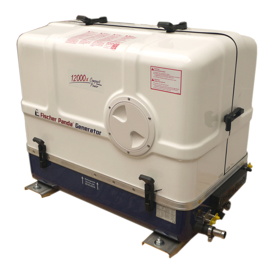
- Page 1 Manual marine generator Panda 12000x PMS 12 kVA 230V - 50 Hz Panda 15000x PMS 15 kVA 230V - 50 Hz Super silent technology Panda_12000-15000_xControl_PMS_eng.R01 18.12.15...
-
Page 2: Current Revision Status
Duplication and change of the manual is permitted only in consultation with the manufacturer! Fischer Panda GmbH, 33104 Paderborn, reserves all rights regarding text and graphics. Details are given to the best of our knowledge. No liability is accepted for correctness. Technical modifications for improving the product without previous notice may be undertaken without notice. -
Page 3: Table Of Contents
3.5.1 Bolted Fischer Panda transport box ................... 32 3.5.2 Fischer Panda transport box with metal tab closure ............32 Opening the MPL sound insulation capsule ..................33 3.6.1 Opening the GFK sound insulation capsule ............... 34 Transport and loading/unloading .................... - Page 4 Protection conductor: ......................53 5.3.5 Operating control system on the Fischer Panda generator ..........53 Instructions for capacitors - not present at all models................. 53 Checks before start - see remote control panel data sheet ..............53 Starting the generator - see remote control panel data sheet............
- Page 5 Installation of the cooling system - raw water ..................58 6.4.1 General information ......................58 6.4.2 Fischer Panda installation kit - raw water ................58 6.4.3 Installation of the through hull fitting in Yachts - scheme ........... 60 6.4.4 Quality of the raw water sucking in line ................
- Page 6 7.10.1.2 Demounting the backend bearing ..............124 7.10.1.3 Installing the new backend bearing ..............125 7.11 Checking the oil level of the generator end bearing at Fischer Panda generators ......128 7.11.1 Oil level check ........................129 7.11.2...
- Page 7 Inhalt / Contens 7.11.3 Refiller-Set ........................130 7.11.4 Screw plug ........................130 7.12 Replacement of the oil-cooled backend bearing ................131 7.12.1 Exchange oil-cooled bearing .................... 131 7.12.2 Demounting the bearing ....................131 7.13 Ventilating the fuel system........................ 143 7.13.1 Replacement of the fuel filter ..................
- Page 8 Inhalt / Contens Overloading the generator ........................ 186 8.6.1 Monitoring the Generator Voltage ..................187 8.6.2 Automatic voltage monitoring and auto-shut down ............187 Generator-Output Voltage is too low ....................188 8.7.1 Check and discharge the capacitors ................. 188 8.7.2 Checking the Capacitors ....................
- Page 9 Inhalt / Contens 11.1.2 xControl – GC-S ......................213 11.1.3 xControl - CB-G ........................ 214 11.2 Installation............................214 11.2.1 Installation of the Electronic Control Unit (ECU) xControl - GC-S ........214 11.2.2 Installation of the Connection Box xControl - CB-G ............214 11.2.3 Installation of the xControl - CP-G ..................
- Page 10 Inhalt / Contens 11.7.3 Technical Data of the GC-S ....................248 11.8 ................................249 Seite/Page 10 Inhalt/Contens 18.12.15...
- Page 11 Not only do you have a Fischer Panda generator on board, you also have worldwide support from the Fischer Panda Team. Please take the time to read this and find how we can support you further.
-
Page 12: General Instructions And Regulations
General Instructions and Regulations 1. General Instructions and Regulations 1.1 Safety first! These symbols are used throughout this manual and on labels on the machine itself to warn of the possibility of personal injury of lethal danger during certain maintenance work or operations. Read these instructions carefully. Can cause acute or chronic health impairments or death WARNING: Hazardous materials even in very small quantities if inhaled, swallowed, or... - Page 13 General Instructions and Regulations Touching of the corresponding parts and systems is PROHIBITED: Do not touch prohibited. Danger for life! Working at a running generator can DANGER: Automatic start-up result in severe personal injury. The generator can be equipped with a automatic start device. This means, an external signal may trigger an automatic start-up.
- Page 14 General Instructions and Regulations Warning of substances that may cause an explosion under WARNING: Explosion hazard certain conditions, e.g. presence of heat or ignition sources. Warning of hot surfaces and liquids. Burn/scalding hazard. WARNING: Hot surface Warning of substances that cause chemical burns upon WARNING: Danger due to corrosive substances, contact.
- Page 15 General Instructions and Regulations Wearing the applicable snugly fitting protective clothing MANDATORY INSTRUCTION: Wear snugly fitting provides protection from hazards and can prevent damage to protective clothing (PPE). your health. Wearing hearing protection provides protection from acute MANDATORY INSTRUCTION: Wear hearing and gradual hearing loss.
-
Page 16: Tools
General Instructions and Regulations 1.2 Tools These symbols are used throughout this manual to show which tool must be used for maintenance or installation. Spanners W.A.F X = width across flats of X mm Hook wrench for oil filter Screw driver, for slotted head screws and for Phillips head screws Multimeter, multimeter with capacitor measuring unit Socket wrench set Hexagon socket wrench set... - Page 17 General Instructions and Regulations Clamp-on ammeter (DC for synchronous generators; AC for asynchronous generators) Torque wrench 18.12.15 Kapitel/Chapter 1: General Instructions and Regulations - Seite/Page 15...
-
Page 18: Manufacturer Declaration In Accordance With The Machinery Directive 2006/42/Ec
• You will receive free upgrades as necessary. Additional advantages: Based on your complete data record, Fischer Panda technicians can provide you with fast assistance, since 90 % of the disturbances result from defects in the periphery. Problems due to installation errors can be recognized in advance. -
Page 19: Safety Instructions - Safety First
General Instructions and Regulations 1.5 Safety Instructions - Safety First! 1.5.1 Safe operation Careful handling of the equipment is the best insurance against an accident. Read the manual diligently, and make sure you understand it before starting up the equipment. All operators, regardless of their experience level, shall read this manual and additional pertinent manuals before commissioning the equipment or installing an attachment. -
Page 20: Safe Handling Of Fuels And Lubricants
General Instructions and Regulations 1.5.5 Safe handling of fuels and lubricants Keep fuels and lubricants away from naked fire. Before filling up the tank and/or applying lubricant, always shut down the generator and secure it against accidental start-up. Do not smoke and avoid naked flame and sparking near fuels and the generator. Fuel is highly flammable and may explode under certain conditions. -
Page 21: Safety Precautions Against Burns And Battery Explosions
Do not mix different anti-freeze agents. The mixture may cause a chemical reaction generating harmful substances. Use only anti-freeze that was approved by Fischer Panda. Protect the environment. Collect drained fluids (lubricants, anti-freeze, fuel), and dispose of them properly. -
Page 22: Implementation Of Safety Inspections And Maintenance
General Instructions and Regulations 1.5.10 Implementation of safety inspections and maintenance Disconnect the battery from the engine before performing service work. Affix a sign to the control panel - both the main and the corresponding slave panel - with the instruction “DO NOT START UP - MAINTENANCE IN PROGRESS“... -
Page 23: Protective Conductor And Potential Equalisation
General Instructions and Regulations 1.6.1.1 Protective conductor and potential equalisation: Electric current below 48 V may be life-threatening. Fort this reason systems are grounded with a protective conductor. In connection with a RCD the current supply will be disconnected in case of a failure. Appropriate safety precautions like the RCD and corresponding fuses have to be provided by the customer to guarantee a save operation of the generator. -
Page 24: Safety Instructions Concerning Cables
General Instructions and Regulations 1.6.1.5 Safety instructions concerning cables Cable types It is recommended to use cables that are in compliance with the standard UL 1426 (BC-5W2) with type 3 (ABYC section E-11). Cable cross-section The cable shall be selected taking into account the amperage, cable type, and conductor length (from the positive power source connection to the electrical device and back to the negative power source connection). -
Page 25: General Safety Instructions For Handling Batteries
The battery terminals must be protected against accidental short-circuiting. Inside the Fischer Panda generator capsule, the positive battery cable must be routed so that it is protected from heat and vibrations by means of an adequate conduit/protective sleeve. It must be installed so that it does not come into contact with rotating parts or such that heat up during operation such as pulley, exhaust manifold, exhaust pipe, and motor itself. - Page 26 Check the battery near vibrating components regularly for chafing and insulation defects. ATTENTION! For battery charger generators (Fischer Panda AGT-DC)! Prior to installation, verify that the voltage of the battery bank complies with the output voltage of the generator.
-
Page 27: In Case Of Emergency First Aid / Im Notfall - Erste Hilfe
In case of Emergency First Aid / Im Notfall - Erste Hilfe 3. In case of Emergency First Aid / Im Notfall - Erste Hilfe First Aid in case of accidents by electrical shocks 5 Safety steps to follow if someone is the victim of electrical shock Do not touch the injured person while the generator is running. -
Page 28: When An Adult Stops Breathing
In case of Emergency First Aid / Im Notfall - Erste Hilfe 3.1 WHEN AN ADULT STOPS BREATHING DO NOT attempt to perform the rescue breathing Warning: techniques provided on this page, unless certified. Performance of these techniques by uncertified personnel could result in further injury or death to the victim. -
Page 29: Basics
This manual contains the working instructions and operating guidelines for the owner and user of Fischer Panda generators. The manual is the base and the guideline for the correct installation and maintenance of Fischer Panda generators. It does not substitute the technical evaluation and should be used as an example guide only. The installation must be undertaken and proved by a suitable qualified/trained person and should be in accordance with the law as required by the country and special situation. -
Page 30: User
Basics 3.2.3 User Users are persons, established by the operator, to operate the generator. The operator has to ensure that the user has read and understood the manual and that all hazard notes and safety instructions are respected. The user must be instructed by the operator regarding his activity at the generator, especially concerning the maintenance. - Page 31 Basics 3. AC-Control Box Fig. 3.3-3: AC-Control box representative picture Not present at all models 4. FP- Bus cable 15 mtr Fig. 3.3-4: FP- Bus cable 15 mtr 5. Termination resistor Fig. 3.3-5: Termination resistor 18.12.15 Kapitel/Chapter 3: Basics - Seite/Page 31...
-
Page 32: Range Of Operation
4. Remove the bolts for sidewalls / floor pallet 5. Remove the sidewalls 6. Open the generator attachment 3.5.2 Fischer Panda transport box with metal tab closure 1. Bend up the metal tab closures on the transport box lid 2. Remove the cover 3. -
Page 33: Opening The Mpl Sound Insulation Capsule
Basics 3.6 Opening the MPL sound insulation capsule To open the sound insulation capsule, the closures must Fig. 3.6-1: Sound insulation capsule, side part be rotated roughly 180° counter-clockwise. Use a flat head screwdriver. Pull the sidewalls out by gripping into the slots. -
Page 34: Opening The Gfk Sound Insulation Capsule
3.7.1 Transporting the generator • The generator must always be upright for transport. • For transport, the Fischer Panda transport box shall be used for the generator. The generator shall be securely attached to the bottom of the box. • For loading/unloading, an adequate industrial truck shall be used. -
Page 35: Special Service Instructions And Measures For Extended Machine Downtimes And Decommissioning
The decommissioning and storage must be undertaken and Note: proved regarding the operation and storage situation. Fischer Panda takes no responsibilty for damages through wrong decommissioning and storage. Downtimes are categorised in the following groups: • Short downtime (1 to 3 months) •... -
Page 36: Measures For Short Downtimes
- 25.2 V upper open-circuit voltage (full battery) - trickle charge full battery at 26.4 V. These values are based on a battery temperature of 20-25°C. Observe the instructions from the battery manufacturer. Fischer Panda recommends: Note: Starter battery recommendation • Install battery circuit breaker and switch to OFF on the machine. -
Page 37: Measures For Removing Surface Protection After Medium Term Downtimes
Basics • Spray engine parts and V-belt disks with preservative. • Clean air filter housing and spray with preservative (metal housing only). • Close off intake and exhaust apertures (e.g. with tape or end caps). Before recommissioning, remove preservatives and Attention! protective measures. -
Page 38: Measures For Removing Surface Protection After Extended Downtimes / Recommissioning (Over 6 Months)
• Hold stop lever on generator motor in neutral position and crank starter for approx. 10 seconds. Then, pause for 10 seconds. Repeat this procedure 2 times. • Perform visual check of the generator similar to initial commissioning and start up generator. Fischer Panda recommends: Note: After extended downtimes, a full 150 h inspection as per the inspection list should be performed. -
Page 39: The Panda Generator
The Panda Generator 4. The Panda Generator 4.1 Type plate at the Generator Fig. 4.1-1: Type plate at the generator Fig. 4.1-2: Description type plate 18.12.15 Kapitel/Chapter 4: The Panda Generator - Seite/Page 39... -
Page 40: Description Of The Generator
The Panda Generator 4.2 Description of the Generator 4.2.1 Right Side View Fig. 4.2.1-1: Right Side View 01. Water-cooled exhaust manifold / Heat exchanger (inside) 09. Flat fuse 02. DC-alternator 10. Ground isolation relay (option) 03. V-belt for DC-alternator and cooling water pump 11. -
Page 41: Left Side View
The Panda Generator 4.2.2 Left Side View Fig. 4.2.2-1: Left Side View 01) Charge control for DC-alternator 07) xControl ECU 02) Air suction housing with air filter 08) Oil dipstick 03) Actuator for speed control 09) Seawater pump 04) Generator housing with winding 10) Fuel solenoid valve 05) Cooling water connection block 11) Internal cooling water pump... -
Page 42: Font View
The Panda Generator 4.2.3 Font View Fig. 4.2.3-1: Front View 16 17 01) Ventilation screw thermostat housing 10) Fuel intake connection (feed line) 02) Fuel solenoid valve 11) Fuel backflow connection (return line) 03) Internal cooling water pump 12) xControl connection panel 04) Alternator DC 13) Oil drain hose 05) V-belt for DC-alternator and internal cooling water pump... -
Page 43: Back View
The Panda Generator 4.2.4 Back View Fig. 4.2.4-1: Back View 01. Generator terminal box 04) Generator front plate 02) Air suction housing with air filter 05) Oil cooled bearing 03) Capacitor 06) Cooling water connection block 18.12.15 Kapitel/Chapter 4: The Panda Generator - Seite/Page 43... -
Page 44: View From Above
The Panda Generator 4.2.5 View from above Fig. 4.2.5-1: View from above 01) Ventilation screw fuel solenoid valve 07) Water cooled exhaust manifold / Heat exchange (inside) 02) Ventilation screw internal cooling water pump 08) Injection nozzle 03) Ventilation screw thermostat housing 09) Cylinder head thermosensor 04) Thermostat housing with thermostat set 10) Air suction housing with air filter... -
Page 45: Details Of Functional Units
The Panda Generator 4.3 Details of functional units 4.3.1 xControl panel The control panel is fitted with various monitoring functions, which increase functional reliability and operating safety of the generator. Various parts of the generator are monitored with sensors which, when triggered, generate an error message and can shut down generator operation under certain circumstances to prevent damage. -
Page 46: The Cooling System - Schema
The Panda Generator 4.3.2 The Cooling System - Schema Fig. 4.3.2-1: The Cooling System - Schema Seite/Page 46 - Kaptitel/Chapter 4: The Panda Generator 18.12.15... -
Page 47: The Fuel System - Schema
The Panda Generator 4.3.3 The Fuel System - Schema Fig. 4.3.3-1: The Fuel System - Schema 18.12.15 Kapitel/Chapter 4: The Panda Generator - Seite/Page 47... -
Page 48: The Operation Surveillance System
The Panda Generator 4.3.4 The operation surveillance system Thermo-sensor at cylinder head Fig. 4.3.4-1: Thermo-seneor at cylinder head The thermo-sensor at the cylinder head serves to monitor the generator temperature. Thermo-sensor at exhaust connection Fig. 4.3.4-2: Thermo-sensor at exhaust connection If the impeller pump stops and delivers no more raw water, the exhaust connection becomes extremely hot. - Page 49 The Panda Generator Thermo-switch at the front plate (Models with oil cooled Fig. 4.3.4-4: Oil thermo-switch bearing only) The generator bearing is equipped with an oil thermo-switch, which switches the engine off, if the oil temperature becomes too high. At generators with xControl the thermo switch is for service only Oil pressure switch Fig.
-
Page 50: The Oil Circuit - Schema
The Panda Generator 4.3.5 The Oil Circuit - Schema Fig. 4.3.5-1: The Oil Circuit - Schema 4.4 Remote Control Panel - see separate Control Panel Manual 4.4.1 Starting the Generator - see separate Control Panel Manual 4.4.2 Stopping the Generator - see separate Control Panel Manual Seite/Page 50 - Kaptitel/Chapter 4: The Panda Generator 18.12.15... -
Page 51: Generator Operation Instruction
Generator operation instruction 5. Generator operation instruction 5.1 Personal requirements Only instructed persons are allowed to run the generator. Instructed Persons has read the manual of the generator and all ancillary components and external equipment. He must be acquaint with the specific risks and safety instruc- tions. -
Page 52: Pre-Heating The Diesel Motor
It is harmless for the generator to deliver full nominal power for 2-3 hours. The hole conception of the Fischer Panda generator make sure, that the full power operation at extreme condition will not increase the engine temperatures over. Please note that the emissions of the generator also increase at full power operation. -
Page 53: Protection Conductor
5.3.5 Operating control system on the Fischer Panda generator Fischer Panda generators are equipped with various sensors/temperatures switches. The combustion engine is further equipped with a oil pressure control switch, which switches the motor off, if the oil pressure sinks to a particu- lar level. -
Page 54: Starting The Generator - See Remote Control Panel Data Sheet
Generator operation instruction 5.6 Starting the generator - see remote control panel data sheet The instructions and regulations of the remote control Note: panel data sheet must be respected. Respect the safety instruction in front of this manual. 5.7 Stopping the generator - see remote control panel data sheet The instructions and regulations of the remote control Note: panel data sheet must be respected. -
Page 55: Installation Instructions
Damages caused by faulty or incorrect installation are not covered by the warranty. 6.1 Personal requirements The described installation must be done by a technical trained person or a Fischer Panda service point. 6.1.1 Hazard notes for the installation see “Safety first!” on Page 12. -
Page 56: Place Of Installation
Installation Instructions - Remove oil and fuel residues from the generator and floor. Danger!: Danger of poisoning Contact with engine oil, antifreeze and fuel can result in . Therefor: damage to health - Avoid skin contact with engine oil, fuel and antifreeze. - Remove oil and fuel splashes and antifreeze from the skin immediately. -
Page 57: Preparing The Base - Placement
Installation Instructions 6.2.2 Preparing the base - placement Since Panda generators have extremely compact dimensions, they can be installed in tight locations. Attempts are sometimes made to install them in almost inaccessible places. Please consider that even almost maintenance-free machinery must still remain accessible at least at the front (drive belt, water pump) and the service-side (actuator, dipstick). -
Page 58: Installation Of The Cooling System - Raw Water
The genset should have its own raw water (coolant water) inlet and should not be connected to any other engine systems. Ensure that the following installation instructions are complied with: 6.4.2 Fischer Panda installation kit - raw water The following additional components will be required for Note: the specified installation. - Page 59 Installation Instructions Raw water filter Fig. 6.4.2-4: Raw water filter Spiral coiled tube with metal spiral bead Fig. 6.4.2-5: Spiral coiled tube with metal spiral bead Ventilation valve Fig. 6.4.2-6: Ventilation valve Hose clamps Fig. 6.4.2-7: Hose clamps 18.12.15 Kapitel/Chapter 6: Installation Instructions - Seite/Page 59...
-
Page 60: Installation Of The Through Hull Fitting In Yachts - Scheme
Installation Instructions 6.4.3 Installation of the through hull fitting in Yachts - scheme It is good practice for yachts to use a through hull fitting Fig. 6.4.3-1: Position of the through hull fitting with an integrated strainer. The through hull fitting (raw water intake) is often mounted against the sailing direction to induce more water intake for cooling. - Page 61 Installation Instructions Contact Fischer Panda for further information. Never change the impeller for many years, without NOTE: exchanging the old pump. If the sealing ring is defective within the pump, raw water runs into the sound cover of the genset. A repair is then very expensive.
-
Page 62: Raw Water Installation Scheme
Installation Instructions 6.4.5.1 Raw water installation scheme Fig. 6.4.5.1-1: Raw water installation schema Seite/Page 62 - Kaptitel/Chapter 6: Installation Instructions 18.12.15... -
Page 63: Generator Installation Below Waterline
Installation Instructions 6.4.6 Generator installation below waterline If the generator cannot be attached at least 600 mm Fig. 6.4.6-1: Vent valve above the waterline, a vent valve must be installed at the raw water line. Possible heeling must be taken into consideration if installed at the "mid-ship line"! The water hose for the external vent valve is located at the back of the sound insulated capsule. -
Page 64: Raw Water Installation Scheme
Installation Instructions 6.4.6.1 Raw water installation scheme Fig. 6.4.6.1-1: Raw water installation schema Seite/Page 64 - Kaptitel/Chapter 6: Installation Instructions 18.12.15... -
Page 65: Installation Of The Cooling System - Fresh Water
Installation Instructions 6.5 Installation of the cooling system - fresh water 6.5.1 Position of the external cooling water expansion tank Position of the external cooling water expansion tank Fig. 6.5.1-1: Position of the external cooling water expansion tank The Panda generator is normally supplied with an additional, external cooling water expansion tank. -
Page 66: Scheme For Freshwater Circuit At Two Circuit Cooling System
Installation Instructions 6.5.2 Scheme for freshwater circuit at two circuit cooling system Fig. 6.5.2-1: Scheme for freshwater circuit at two circuit cooling system 1. Expansion tank 4. Fresh water pump 2. Exhaust manifold 5. Heat exchanger 3. Thermostat housing 6. Cooling water connection block 6.6 Ventilation of the coolant circuit / freshwater Special notes for the ventilation of the cooling system Attention... - Page 67 Installation Instructions Expansion tank Fig. 6.6-1: Expansion tank 7. Open the ventilating screw on the thermostat housing. Fig. 6.6-2: Ventilating screw on the thermostat housing Use spanner size 10 mm. 8. Pour cooling water into the external expansion tank. Fig. 6.6-3: filling level 20% 9.
-
Page 68: Pressure Test For Controlling The Cooling Water Circuit
Installation Instructions stood still for a long time. During the ventilating process repeated checks must be ATTENTION! made to check the cooling water is indeed circulating. If there are air bubbles in the internal cooling water pump, it could be that the cooling water is not circulating. The generator will heat up very quickly and switch off, because of overheating. -
Page 69: Installation Of The Water Cooled Exhaust System
Installation Instructions 6.7 Installation of the water cooled exhaust system 6.7.1 Fischer Panda installation kit - Exhaust System The following additional components will be required for Note: the specified installation. You can purchase them as an installation kit or separately at Fischer Panda. -
Page 70: Installation Of The Standard Exhaust System
Installation Instructions Sleeve adapter Fig. 6.7.1-5: sleeve adapter Exhaust hose black with wireinlay Fig. 6.7.1-6: Exhaust hose black with wireinlay Seacock Fig. 6.7.1-7: Seacock Hoseclamps Fig. 6.7.1-8: Hoseclamp 6.7.2 Installation of the standard exhaust system The generator exhaust system must remain completely independent and separate from the exhaust system of any other unit(s) on board. -
Page 71: Installation Of The Waterlock
Installation Instructions Fig. 6.7.2-1: Installation Scheme Standard Exhaust System Installation of the waterlock Pay attention to the right flow direction throught the Note!: waterlock. Unfortunately, it can occasionally occur that, because of an disadvantageous mounting position of the waterlock, sea water gets into the diesel engines’... -
Page 72: Possible Cause For Water In The Exhaust Hose
Installation Instructions certainly be reasonable to immediately inject plenty penetrating oil through the intake stack and to slowly turn the engine with the starter motor. The cooling water can reach the exhaust area via the exhaust hose as well as via the cooling water feed. 6.8.1 Possible cause for water in the exhaust hose 6.8.1.1 Possible cause: exhaust hose If the cause is the exhaust hose itself, the following points are to be checked at the hose:... -
Page 73: The Volume Of The Waterlock
Installation Instructions Fig. 6.8.2-1: Installation area of the waterlock 6.8.3 The volume of the waterlock The waterlock must be measured so large, that it can take the entire amount of water flowing back from the exhaust hose. The amount of water depends on the hoses’ length (L) and its cross section. While the diesel engine is running, cooling water is continuously injected into the exhaust system and is carted outside with the emissions by the exhaust gas pressure. - Page 74 Installation Instructions Fig. 6.8.3.0-1: Volume of the waterlock If there are any doubts, a verification can easily be made by temporarily using a clear-sighted hose (1) as exhaust hose. In that way, the cooling water level can be checked very easily. Fig.
-
Page 75: Ideal Position Of The Waterlock
Installation Instructions 6.8.3.1 Ideal position of the waterlock Important Note! The ideal position of the waterlock would be in center underneath the generator. Only in this position it is assured that the water level cannot change drastically in tilted position by the waterlock moving out of the center line. - Page 76 Installation Instructions Fig. 6.8.3.1-3: Tilted position 30 degrees Tilted position 30 degrees - Fig. 6.11.3.1-3 The distance of the water level, even in ideal position, changes that only 458 mm distance remain. So the critical distance is under-run already. Fig. 6.8.3.1-4: Tilted position 45 degrees Tilted position 45 degrees - Fig.
- Page 77 Installation Instructions Summary: The preset minimum height of 600 mm must be regarded unconditionally and is only valid if the waterlock is mounted in its ideal position in center underneath the generator. A higher position is highly recommended if it has to be reckoned with tilted positions of 45 degrees.
-
Page 78: Example Of The Installation Of The Waterlock Off-Center And Possible Effects
Installation Instructions 6.8.3.2 Example of the installation of the waterlock off-center and possible effects: The following pictures are primarily relevant for an installation of the generator with the waterlock on sailing yachts. A change in the mounting position caused by tilted position does not have to be reckoned concerning motor yachts. Here it is only necessary to regard that the volume of the waterlock is measured so large that it can take the entire amount of water flowing back, and at the same time, maintains the minimum distance of 600 mm. - Page 79 Installation Instructions Fig. 6.8.3.2-3: Tilted position 30 degrees Tilted position 30 degrees - Fig. 6.11.3.2-3 The distance between the hydrostatic head and the critical point at the exhaust elbow is only 216 mm. This means that in a tilted position of 30 degrees you already face the highest risk of sea water sloshing into the combustion chamber.
- Page 80 Installation Instructions B) Installation distance between waterlock and the generator’s center line 1000 mm Fig. 6.8.3.2-5: waterlock, 1000 mm next to center line Fig. 6.8.3.2-6: Tilted position 15 degrees Tilted position 15 degrees - Fig. 6.11.3.2-6 The distance is, contrary to the original 600 mm, only 327 mm. This is very close to the critical point already. Seite/Page 80 - Kaptitel/Chapter 6: Installation Instructions 18.12.15...
-
Page 81: Exhaust / Water Separator
In order to reduce the noise level of the generator unit to a minimum, an optional exhaust outlet muffler can be mounted next to the through-hull fitting. Additionally there is a component at Fischer Panda, which acts as both an „exhaust goose neck“, and water separator. - Page 82 Installation Instructions Fig. 6.9.0-1: Installation Scheme exhaust / water separator Seite/Page 82 - Kaptitel/Chapter 6: Installation Instructions 18.12.15...
-
Page 83: Installation Exhaust Water Separator
Installation Instructions 6.9.1 Installation exhaust water separator If the exhaust water separator was sufficiently highly installed, a goose neck is no longer necessary. The exhaust/ water separator fulfils the same function. If the „Super silent“ exhaust system were installed correctly, the generator will not disturb your boat neighbour. -
Page 84: Installation Of The Water Cooled Exhaust System
Installation Instructions 6.10 Installation of the water cooled exhaust system 6.10.1 Installation of the standard exhaust system The generator exhaust system must remain completely independent and separate from the exhaust system of any other unit(s) on board. The water lock must be installed at the lowest point of the exhaust system. An optional noise insulated water lock can also be installed. -
Page 85: Installation Of The Waterlock
Installation Instructions 6.11 Installation of the waterlock Pay attention to the right flow direction throught the Note!: waterlock. Unfortunately, it can occasionally occur that, because of an disadvantageous mounting position of the waterlock, sea water gets into the diesel engines’ combustion chamber. This disables the diesel engine by irreversible damages. Quite frequently, this leads to discussions during which the parties involved in the yachts’... -
Page 86: Installation Area Of The Waterlock
Installation Instructions b) Position of the venting valve is too far from the ships’ center line. The water reaches the exhaust area when the ship is tilted. c) The venting valve does not work, because it jams or it is clotted. (The venting valve’s function needs to be checked regularly.) As it consistently happens that functioning risks are not realised during the laying of the exhaust hose, the following explanations refer explicitly to the exhaust hose. - Page 87 Installation Instructions hose. The amount of water depends on the hoses’ length (L) and its cross section. While the diesel engine is running, cooling water is continuously injected into the exhaust system and is carted outside with the emissions by the exhaust gas pressure.
-
Page 88: Ideal Position Of The Waterlock
Installation Instructions 6.11.3.1 Ideal position of the waterlock Important Note! The ideal position of the waterlock would be in center underneath the generator. Only in this position it is assured that the water level cannot change drastically in tilted position by the waterlock moving out of the center line. - Page 89 Installation Instructions Fig. 6.11.3.1-3: Tilted position 30 degrees Tilted position 30 degrees - Fig. 6.11.3.1-3 The distance of the water level, even in ideal position, changes that only 458 mm distance remain. So the critical distance is under-run already. Fig. 6.11.3.1-4: Tilted position 45 degrees Tilted position 45 degrees - Fig.
- Page 90 Installation Instructions Summary: The preset minimum height of 600 mm must be regarded unconditionally and is only valid if the waterlock is mounted in its ideal position in center underneath the generator. A higher position is highly recommended if it has to be reckoned with tilted positions of 45 degrees.
-
Page 91: Example Of The Installation Of The Waterlock Off-Center And Possible Effects
Installation Instructions 6.11.3.2 Example of the installation of the waterlock off-center and possible effects: The following pictures are primarily relevant for an installation of the generator with the waterlock on sailing yachts. A change in the mounting position caused by tilted position does not have to be reckoned concerning motor yachts. Here it is only necessary to regard that the volume of the waterlock is measured so large that it can take the entire amount of water flowing back, and at the same time, maintains the minimum distance of 600 mm. - Page 92 Installation Instructions Fig. 6.11.3.2-3: Tilted position 30 degrees Tilted position 30 degrees - Fig. 6.11.3.2-3 The distance between the hydrostatic head and the critical point at the exhaust elbow is only 216 mm. This means that in a tilted position of 30 degrees you already face the highest risk of sea water sloshing into the combustion chamber.
- Page 93 Installation Instructions B) Installation distance between waterlock and the generator’s center line 1000 mm Fig. 6.11.3.2-5: waterlock, 1000 mm next to center line Fig. 6.11.3.2-6: Tilted position 15 degrees Tilted position 15 degrees - Fig. 6.11.3.2-6 The distance is, contrary to the original 600 mm, only 327 mm. This is very close to the critical point already. 18.12.15 Kapitel/Chapter 6: Installation Instructions - Seite/Page 93...
-
Page 94: Exhaust / Water Separator
In order to reduce the noise level of the generator unit to a minimum, an optional exhaust outlet muffler can be mounted next to the through-hull fitting. Additionally there is a component at Fischer Panda, which acts as both an „exhaust goose neck“, and water separator. - Page 95 Installation Instructions Water flow exhaust water Separator Fig. 6.12.0-1: Water Flow Exhaust Water Separator Water flow exhaust water Separator Fig. 6.12.0-2: Exhaust Water Separator (1) Raw water outlet (2) Hose connector (3) Reducer (if required) (4) Hose (5) Hose connector (6) Sea cock (7) Hull outlet (8) Hose Clips...
-
Page 96: Installation Exhaust Water Separator
Installation Instructions 6.12.1 Installation exhaust water separator Fig. 6.12.1-1: Installation Exhaust Water Separator 1. Generator 4. Silencer 2. Silencer / Water lock 5. Sea cock 3. Exhaust-Water-Separator 6. Hull outlet If the exhaust water separator was sufficiently highly installed, a goose neck is no longer necessary. The exhaust/ water separator fulfils the same function. -
Page 97: Fuel System Installation
- Water lock not far enough below the lowest level of the generator - Distance water lock to exhaust/water separator too large 6.13 Fuel system installation 6.13.1 Fischer Panda installation kit - Fuel system The following additional components will be required for Note: the specified installation. - Page 98 Installation Instructions No return valve Fig. 6.13.1-2: No return valve representative picture Pre filter with water separator Fig. 6.13.1-3: Pre filter with water separator representative picture Pre filter with water separator Fig. 6.13.1-4: Pre filter with water separator Alternative Article representative picture Seite/Page 98 - Kaptitel/Chapter 6: Installation Instructions 18.12.15...
-
Page 99: The Following Items Need To Be Installed
The external Fuel pump should be installed near the tank Electrical fuel pump Fig. 6.13.1-1: electrical fuel pump With the Fischer Panda generator is usually supplied an external, electrical fuel pump (DC). The fuel pump must be installed close at the fuel tank. The electrical connections is prepared at the generator. - Page 100 Installation Instructions Fig. 6.13.1-2: Fuel system - schema 1. Fuel tank 4. Non return valve 2. external fuel pump 5. Fuel fine filter 3. external fuel prefilter with water separator 6. Generator Seite/Page 100 - Kaptitel/Chapter 6: Installation Instructions 18.12.15...
-
Page 101: Connection Of The Fuel Lines At The Tank
Installation Instructions External fine filter Fig. 6.13.1-3: externer Feinfilter At generators with Kubota EA 300 or Farymann engines, the fine filter is delivered with the generator. This fine filter should be installed in the fuel feed line next to the generator. representative picture 6.13.2 Connection of the fuel lines at the tank General fuel feed and return line must be connected to the... -
Page 102: Position Of The Pre-Filter With Water Separator
Installation Instructions 6.13.3 Position of the pre-filter with water separator Inside the generator capsule itself, there is the fuel filter installed (exception: Panda 4500). Additional fuel filters (with water separator) must be mounted outside the capsule in easily accessible places in the fuel lines between the tank intake fuel pump and the diesel motor's fuel pump. - Page 103 Installation Instructions Make sure that the voltage of the starter battery fits to ATTENTION! the start system voltage f.e. 12 V starter battery for a 12 V start system f.e. 24 V starter battery for a 24 V start system (2x12 V batteries in a row) To avoid large voltage drops the battery should be NOTE:...
- Page 104 Installation Instructions Positive battery cable Fig. 6.14.1-1: Positive battery cable The positive (+) battery cable is connected directly to the solenoid switch of the starter. Negative battery cable Fig. 6.14.1-2: Negative battery cable The negative (-) battery cable is connected to the engine foot.
- Page 105 Installation Instructions Fig. 6.14.1-4: Connection starter battery 12 V - schema 1. Generator 3. Fuse 2. Battery block 4. Battery main switch Fig. 6.14.1-5: Connection starter battery 24 V - schema 1. Generator 3. Fuse 2. Battery block 4. Battery main switch 18.12.15 Kapitel/Chapter 6: Installation Instructions - Seite/Page 105...
-
Page 106: How To Connect Two 12 V Batteries To A 24 V Battery Bank
Installation Instructions 6.14.2 How to connect two 12 V batteries to a 24 V battery bank The starter batteries have to be connected in this order: Fig. 6.14.2-1: Installation starter battery 1. (+) cable of first battery 2. (-) cable of second battery Fig. -
Page 107: Connection Of The Xcontrol Panel - See Separate Xcontrol Manual
Installation Instructions 4. (-) cable of first battery Fig. 6.14.2-4: Installation starter battery 5. Disconnect the batteries in reverse procedure. 6.14.3 Connection of the xControl panel - see separate xControl manual 6.15 Generator AC System Installation Before the electrical system is installed, READ the Warning!: Electrical Voltage SAFETY INSTRUCTIONS of this manual FIRST! Be sure that all electrical installations (including all safety... -
Page 108: Installation With Looped-In Ac-Control Box
Installation Instructions Fig. 6.16-1: AC-Control box - example 1. Terminal block for excitation 3. Capacitors 2. Boost solenoid 6.16.1 Installation with looped-in AC-Control box All electrical safety installations have to be made on board (RCD etc.). Seite/Page 108 - Kaptitel/Chapter 6: Installation Instructions 18.12.15... -
Page 109: Installation Ac-Box / Distribution Panel Connected Separately
Installation Instructions Fig. 6.16.1-1: Installation with looped-in AC Control box 1. Generator 4. Distribution panel 2. Battery 5. Remote control panel 3. AC-Control box 6. Diesel pump 6.16.2 Installation AC-Box / Distribution panel connected separately Fig. 6.16.2-1: Installation AC-Box / Distribution panel connected separately 1. -
Page 110: Electronic Voltage Control Xcontrol
Installation Instructions 6.16.3 Electronic voltage control xControl The xControl controls the generator voltageand motor speed. An actuator/servo on the injection pump can increasethe engine speed compared to the idle speed. If the generator runs without load, the frequency should be approx. 48,5 - 49 Hz (50 Hz System) or 58,5 - 59 Hz (60 Hz System). -
Page 111: Special Recommendations
Installation Instructions separate. As disconnector a cam switch should be used. This Fig. 6.16.4-1: 3-way cam switch switch should have three positions: "Shore power" - "OFF" - "Generator". If an (DC-AC) inverter is used, a fourth position will be required. 0 Off I Generator II Shore power connection... -
Page 112: Isolation Test
The original initial operation record has to be sent to Note: Fischer Panda to receive the complete guarantee. Please make a copy for your own documentation. Seite/Page 112 - Kaptitel/Chapter 6: Installation Instructions 18.12.15... -
Page 113: Maintenance Instructions
7.1 Personal requirements All maintenance, if not special marked, can be done by the trained persons. Further maintenance must be done by technical personal or Fischer Panda service points. 7.2 Hazard notes for the maintenance Follow the general safety instruction at the front of this Notice!: manual. - Page 114 Maintenance Instructions Contact with engine oil, antifreeze and fuel can result in Danger!: Danger of poisoning damage to health. Therefor: • Avoid skin contact with engine oil, fuel and antifreeze. • Remove oil and fuel splashes and antifreeze from the skin immediately.
-
Page 115: Environmental Protection
Maintenance Instructions 7.3 Environmental protection Danger to the environment due to mishandling! Environmental protection. Significant environmental damage can occur, particularly for incorrect disposal, if environmentally hazardous operating materials are mishandled. Therefore: • Always observe the instructions mentioned below. • Take immediate action if environmentally hazardous materials reach the environment. -
Page 116: Oil Change Intervals
Maintenance Instructions 7.6 Oil Change Intervals The first oil change is to be accomplished after a period of operation from 35 to 50 hours. Afterwards the oil is to be changed after 150 hours. For this, the oil SAE30 for temperatures over 20°C and SAE20 for temperatures between 5°C and 20°C is to be used. -
Page 117: Refilling Oil
• if the oil-level is under the minimum mark by less than 50h, there might be a technical problem! In that case, we recommend going to a shop or a Fischer Panda service point. • if the oil is cloudy or even „creamy“, coolant might have mixed with the oil. See a garage or a Fischer Panda service point immediately. -
Page 118: Replacement Of Engine Oil And Engine Oil Filter
Maintenance Instructions 7.8 Replacement of engine oil and engine oil filter You require: - Engine oil. See attachment. - New oil filter (not with generators with EA300 engines) - Sealing for oil drain screw - Personal protective gear - Container to collect used oil (heat resistant and of sufficient size) - Open-ended wrench for oil drain screw - Paper towels and cloth... - Page 119 Maintenance Instructions 2. Loosen oil filling cap Fig. 7.8-1: Oil filling cap Unscrew the oil filling cap. This is necessary, because otherwise a vacuum will form and the oil can not completely drain off. Sample picture 3. Open oil drain screw. Fig.
-
Page 120: After The Oil Change
Maintenance Instructions Oil screen with generators with EA300 engines Fig. 7.8-4: Oil screen The oil screen should be cleaned every 500 operating hours: to do so follow the instructions in the engine manual. Use spanner size 17 mm. Sample picture 6. -
Page 121: Verifying The Starter Battery And (If Necessary) The Battery Bank
Maintenance Instructions 7.9 Verifying the starter battery and (if necessary) the battery bank Check the condition of the battery. Proceed here as prescribed by the battery manufacturer. If from the battery manufacturer not otherwise mentioned. 7.9.1 Battery 7.9.1.1 Check battery and cable connections •... -
Page 122: Check Electrolyte Density
Maintenance Instructions 7.9.1.3 Check electrolyte density • Measure the electrolyte density of individual cells with a Fig. 7.9.1.3-1: Battery commercial hydrometer. The hydrometer reading (see table on following page) indicates the battery’s state of charge. During measurement, the temperature of the electrolyte should preferably be 20 °C. -
Page 123: Exchange Of Grease Lubricated Bearing
Maintenance Instructions Grease lubricated backend bearing without cooling disc. Fig. 7.10-1: Grease lubricated backend bearing Sample Picture Grease lubricated backend bearing with cooling disc. Fig. 7.10-2: Grease lubricated backend bearing Sample Picture 7.10.1 Exchange of grease lubricated bearing Only special trained persons are allowed to do this STOP! maintenance! DANGER FOR LIFE! - Inappropriate handling can lead to... -
Page 124: Demounting The Cooling Disc (If Existent)
Maintenance Instructions 7.10.1.1 Demounting the cooling disc (if existent) To demount the cooling disc, detach the cooling discs’ Fig. 7.10.1.1-1: Demounting the cooling disc holding nut and take off the disc. Sample Picture 7.10.1.2 Demounting the backend bearing Degrease the spot with a fat solvent as shown, apply Fig. -
Page 125: Installing The New Backend Bearing
Sample picture If there is no suitable extractor available, a suitable Note: extractor can be purchased from Fischer Panda. Check the O-ring seal which is mounted in the bearing cover and replaced if damaged. 7.10.1.3 Installing the new backend bearing Mount bearing case in the generator cap. - Page 126 Maintenance Instructions With the other hand, loosely screw in the ejector screws Fig. 7.10.1.3-2: Bearing case mouting as guide line. Sample Picture Carefully press the bearing case with a soft-head Fig. 7.10.1.3-3: Press fit bearing case hammer (or a hammer plus mandrel) in its hub. Thereby relocated mandrel rotatory after each hit to avoid canting.
- Page 127 Maintenance Instructions Screw in thread rod into the thread hole of the generator Fig. 7.10.1.3-5: Screw in thread rod shaft as far as possible. Sample Picture Slide on ball bearing, pressure ladle, grommet up to the Fig. 7.10.1.3-6: Put on ball bearing shaft, screw on long hexagon nut.
-
Page 128: Checking The Oil Level Of The Generator End Bearing At Fischer Panda Generators
• Mount casing. Sample Picture 7.11 Checking the oil level of the generator end bearing at Fischer Panda generators The oil level check is a visual check. Older generators are equipped with an sight glass, newer ones with an sight hose. -
Page 129: Oil Level Check
If your generator does not feature these control modules or if these are not accessable, please refer to your Fischer Panda distribution partner or to Fischer Panda directly. The correct oil level is at the middle of the sight glass/ sight hose. -
Page 130: Refiller-Set
Maintenance Instructions 3. Now tighten the screw again and fasten it with 20 Nm. 7.11.3 Refiller-Set An appropriate refiller set can be purchased at Fischer Panda. The refiller set contains: Oil: Omala S4 GX 220. Syringe plus hose 7.11.4 Screw plug ATTENTION: Fig. -
Page 131: Replacement Of The Oil-Cooled Backend Bearing
Maintenance Instructions 7.12 Replacement of the oil-cooled backend bearing A bearing replacement should only be executed by a trained professional. 7.12.1 Exchange oil-cooled bearing DANGER TO LIFE! - Inappropriate handling can lead to Warning!: Automatic start health damages or death. The battery bank must always be disconnected (first negative pole, then plus pole), to ensure that the generator can not be started by accident when operations at the generator itself or... - Page 132 Maintenance Instructions Demount the oil cap by loosening the nuts M6 (Tool: Fig. 7.12.2-3: Demounting the oil cap Socket wrench SW10). As shown, degrease the spot with a fat solvent and make Fig. 7.12.2-4: Marking the bearing position a mark with a waterproof pen. Seite/Page 132 - Kaptitel/Chapter 7: Maintenance Instructions 18.12.15...
- Page 133 Maintenance Instructions Unscrew the fastening screws (Tool: Allen wrench SW6). Fig. 7.12.2-5: Loosen fastening screws As shown, screw in 3 lifting screws M8x50 as far as Fig. 7.12.2-6: Insert lifting screws possible by hand. Then screw in those 3 screws with a screw wrench Fig.
- Page 134 Maintenance Instructions Knocking out the ball bearing Fig. 7.12.2-8: Knocking out the ball bearing Put the bearing housing horizontally on e.g. 2 wood ledges, the ball bearing pointing downwards. Alternatively, the bearing housing can rest on the lifting screws. Place an appropriate bolt (e.g. extension of a ratch) on the inner bearing ring.
- Page 135 Maintenance Instructions Dismounted shaft sealing ring Fig. 7.12.2-11: Dismounted shaft sealing ring Remove O-rings from the bearing seat: Fig. 7.12.2-12: Remove o-rings Take both O-rings out of the bearing seat. 18.12.15 Kapitel/Chapter 7: Maintenance Instructions - Seite/Page 135...
- Page 136 Maintenance Instructions Remove O-ring from the oil cap. Fig. 7.12.2-13: Remove O-ring Clean the bearing seat and the oil cap. Slightly lubricate the new O-rings and mount them. Mounting the NEW shaft sealing ring: Fig. 7.12.2-14: Mounting the shaft sealing ring Lubricate/grease the shaft sealing rings’...
- Page 137 Maintenance Instructions Push the sealing ring on the mandrel, the open side Fig. 7.12.2-16: should point towards the handle. The side marked with „X“ is to be used. Mounting of the shaft sealing ring Fig. 7.12.2-17: Fitting the shaft sealing ring Correctly mounted sealing ring Fig.
- Page 138 Maintenance Instructions Clean the shaft Fig. 7.12.2-19: Cleaning the shaft Check the wheel tread for damages Fig. 7.12.2-20: Checking the wheel tread The wheel tread has to be - clean - free of partial damages (drafts, indentations, notches, scratches). Mounting the bearing housing inside the generator cap: Fig.
- Page 139 Maintenance Instructions With the other hand, loosely screw in the lifting screws Fig. 7.12.2-22: Mount the bearing housing for guidance. Now carefully press the bearing housing in its seat with Fig. 7.12.2-23: Mount the bearing housing a soft headed hammer (or hammer plus mandrel). By doing that, shift the mandrel after each scale in a circle to avoid canting.
- Page 140 Maintenance Instructions Mounting the ball bearing: Fig. 7.12.2-25: Mount the thread rod Screw the thread rod into the generator shafts’ tap hole as far as possible. Push the ball bearing, the pressure ladle and the washer Fig. 7.12.2-26: Mount the ball bearing up against the shaft, then screw on the hex nuts.
- Page 141 Maintenance Instructions By doing that, the ball bearing is pressed onto the shaft. Fig. 7.12.2-28: Mount the ball bearing If necessary, hold the crank shaft with an appropriate wrench to keep the diesel engine from rotating concurrently. Press the ball bearing on as far as possible. (Tool: Wrench SW13 and SW22) Hold up the crank shaft Fig.
- Page 142 Oils that have the following specifications, are classified as adequate: synthetic gear oil (PAO) Grades of oil 220 to 320 Minimum requirement gear oil: CLP HC These oils are available at industrial lubricant commerces as well as Fischer Panda. Seite/Page 142 - Kaptitel/Chapter 7: Maintenance Instructions 18.12.15...
-
Page 143: Ventilating The Fuel System
Maintenance Instructions * Oil change intervals every 1500 hours ** Oil change intervals every 300 hours Screw in the ventialtion screw and tighten it (Tool: Allen Fig. 7.12.2-34: Screw in the ventilation screw wrench SW6 - 20 Nm). Remove the start interlock. Re-connect the starter battery. -
Page 144: Replacement Of The Fuel Filter
Maintenance Instructions 3. Pressing the failure bypass switch for approx 3 - 4 Fig. 7.13-2: Ventilation screw at the fuel solenoid valve minutes will loosen the ventilation screw located at the fuel solenoid valve. The button must continue to be pressed, whilst opening the screw. -
Page 145: Optional Fuel Filter With Sight Glass
Maintenance Instructions 7.13.1.1 Optional fuel filter with sight glass The filter change depends on the fuels’ degree of pollution, Fig. 7.13.1.1-1: Fuel filter but should be executed every 300 operating hours at the latest. 01. Fuel filter housing 02. Fuel filter element 03. - Page 146 Maintenance Instructions 3. Screw the new filter element into the mount. Fig. 7.13.1.1-4: Fuel filter 4. Lubricate the sight glasses o-ring with a heat resistant grease (Specification: Antiseize) and screw the sight glass back into its mount (right hand rotation). Seite/Page 146 - Kaptitel/Chapter 7: Maintenance Instructions 18.12.15...
-
Page 147: Checking The Water Separator In The Fuel Supply
Maintenance Instructions 7.14 Checking the water separator in the fuel supply The pre-filter with water separator has a cock underneath, by Fig. 7.14-1: Pre-filter with water separator which means the water can be drained. This water sinks to the bottom, due to the difference in the densities of water and fuel. -
Page 148: Alternative Replacement Of The Air Filter Mat With Pull Out Holder
Maintenance Instructions 7.14.2 Alternative replacement of the air filter mat with pull out holder 1. Air filter housing with pull out holder. Fig. 7.14.2-1: Air suction housing with pull out holder 2. Tip the two fasteners 90°. Fig. 7.14.2-2: Air suction housing with pull out holder 3. - Page 149 Maintenance Instructions 4. Replace the air filter mat. Fig. 7.14.2-4: Air suction housing with pull out holder 5. Re-assembly in reversed order. 18.12.15 Kapitel/Chapter 7: Maintenance Instructions - Seite/Page 149...
-
Page 150: Alternative Replacement Of The Air Filter At Housing With Snap Fasteners
Maintenance Instructions 7.14.3 Alternative replacement of the air filter at housing with snap fasteners 1. Open the combustion air housing by loosening the closure Fig. 7.14.3-1: Air suction housing on the right side of the housing. 01. Closure 2. Open the combustion air housing by loosening the closure Fig. -
Page 151: Ventilation Of The Coolant Circuit / Freshwater
Maintenance Instructions 7.14.4 Ventilation of the coolant circuit / freshwater Special notes for the ventilation of the cooling system Attention If the cooling water is drained, or if other air has entered the cooling system, it is necessary to ventilate the cooling system. - Page 152 Maintenance Instructions 2. Open the ventilating screw on the thermostat casing. Fig. 7.14-3: Ventilating screw on the thermostat housing Use spanner size 10 mm. 3. Pour cooling water into the cooling water filling necks. Fig. 7.14-4: Cooling water filler cap (At generators without filler, The cooling water can be filled into the external expansion tank instead) 4.
-
Page 153: V-Belt Replacement For The Internal Cooling Water Pump
Maintenance Instructions 7.14.5 V-belt replacement for the internal cooling water pump The V-belt wears in a short time due to high ambient temperature within the closed capsule (approx. 85 °C). The air in the generator capsule is not only warm but also very dry. Therefore it is possible, that the „softener“ in the rubber composers wear after a very short time of operation. -
Page 154: The Raw Water Circuit
Maintenance Instructions 3. The alternator must be pressed in the direction of the Fig. 7.14.5-3: Alternator thermostat housing. 4. Exchange the V-belt. Sample Picture 5. Afterwards, the V-belt must be tightened again. Fig. 7.14.5-4: V-belt 6. The V-belt must be tightened in such a way, that it is possible to press it about approx. -
Page 155: Causes With Frequent Impeller Waste
Maintenance Instructions The raw water filter should be released regularly from Fig. 7.15.1-1: Raw water filter arrears. In each case the water cock must be closed before. It is mostly sufficient to beat the filter punnet. If water should seep through the cover of the raw water filter, this may be sealed in no case with adhesive or sealant. -
Page 156: Replacement Of The Impeller
Maintenance Instructions 7.16.1 Replacement of the impeller Close the raw water stop cock. Fig. 7.16.1-1: Raw water cock Representative picture Raw water pump on the front side of the genset. Fig. 7.16.1-2: Raw water pump Representative picture Remove the cover of the raw water pump by loosen the Fig. -
Page 157: Check And Discharge The Capacitors
Maintenance Instructions Fig. 7.16.1-4: Impeller pump Pull to the impeller with a multigrip pliers of the wave. Mark the impeller, to make sure that these is used in the correct position at re-installation. Representative picture Check to the impeller for damage and replace it if Fig. - Page 158 Maintenance Instructions have been removed, the capacitors must be discharged by bridging the capacitor terminals with a discharge reactor. The capacitors can be checked using a multimeter with capacitor measuring. The capacitors fitted inside the cabinet are discharged over the soldered resistor at every capacitor. The discharge over the discharge reactor (see special tools) is security because the capacitor voltage is lethal.
-
Page 159: Replacing The Electric Starter
This can lead to faster deterioration of the capacitors. 7.17.1Replacing the Electric Starter The described procedure is representative for Fischer Panda NOTE:Representative procedure generators. The original location of the item must be taken from the generator description of this manual. - Page 160 Maintenance Instructions 3. Pull off rubber cap. Fig. 7.17-3: Electric starter 4. Loosen hex nut with wrench with W.A.F. 13 mm and remove the electric connections. 5. Loosen the lower attachment screw with a hex socket Fig. 7.17-4: Electric starter wrench.
- Page 161 Maintenance Instructions The upper attachment screw is visible from up top, view Fig. 7.17-6: Electric starter between engine and exhaust manifold. 6. Slide the socket wrench fitted with both extensions under the exhaust manifold and insert in the hex socket screw. Loosen upper attachment screw.
-
Page 162: Replacing The Dc Alternator
Maintenance Instructions 7.18 Replacing the DC Alternator The described procedure is representative for Fischer Panda NOTE:Representative procedure generators. The original location of the item must be taken from the generator description of this manual. All replacements and repairs should be done by a trained person. - Page 163 Maintenance Instructions 3. Pull off rubber caps on the electrical terminals. Fig. 7.18-3: DC alternator 4. Remove nut and washer of the 24 V DP+ terminal (red cable) using a wrench with W.A.F. 10 mm. 5. Remove nut and washer of the exciter terminal (grey Fig.
- Page 164 Maintenance Instructions 8. Loosen bottom fixing screw of the DC alternator with a Fig. 7.18-6: DC alternator wrench with W.A.F. 12 mm (01). 9. Use a wrench with W.A.F. 12 mm (02) for the counter nut. 10.Push the DC alternator toward the thermostat housing. Fig.
- Page 165 Maintenance Instructions 14.Loosen and remove the earthing strip with a size 5 mm Fig. 7.18-9: DC alternator socket wrench. 15.Replace the DC alternator. 16.To reinstall, reverse the order of steps. 18.12.15 Kapitel/Chapter 7: Maintenance Instructions - Seite/Page 165...
-
Page 166: Replacing The Oil Pressure Switch
Maintenance Instructions 7.19 Replacing the Oil Pressure Switch The described procedure is representative for Fischer Panda NOTE:Representative procedure generators. The original location of the item must be taken from the generator description of this manual. All replacements and repairs should be done by a trained person. -
Page 167: Replacing The Oil Pressure Sensor (Optional Component)
Maintenance Instructions 7.19.1 Replacing the oil pressure sensor (optional component) 1. Unscrew both connectors (01) on the oil pressure sensor. Fig. 7.19.1-1: Oil pressure sensor 2. Loosen and remove oil pressure sensor 6R3 using a Fig. 7.19-2: Oil pressure sensor wrench with W.A.F. -
Page 168: Replacing The Injection Nozzles
Maintenance Instructions 7.20 Replacing the Injection Nozzles The described procedure is representative for Fischer Panda NOTE:Representative procedure generators. The original location of the item must be taken from the generator description of this manual. All replacements and repairs should be done by a trained person. - Page 169 Maintenance Instructions 3. Loosen the union nut on the injection lines (1). Wrench Fig. 7.20-3: Injection nozzles with W.A.F. of 17 mm. For assembly: • Blast dust out of the lines using compressed air. Then, reassemble the lines by proceeding in the reverse order of steps.
- Page 170 Maintenance Instructions Removing the nozzle heat shield ring seal within the Fig. 7.20-5: Injection nozzles scope of the maintenance work. IMPORTANT! • Use a phillips screwdriver (1) with a diameter greater than the hole in the heat ring seal (approx. 6 mm (1/4 in)). 1.
-
Page 171: Checking The Flame Glow Plug (Optional Unit)
Maintenance Instructions 7.21 Checking the Flame Glow Plug (optional unit) The described procedure is representative for Fischer Panda NOTE:Representative procedure generators. The original location of the item must be taken from the generator description of this manual. All replacements and repairs should be done by a trained person. -
Page 172: Replacing The Flame Glow Plug
Maintenance Instructions 7.21.1 Replacing the Flame Glow Plug The described procedure is representative for Fischer Panda NOTE:Representative procedure generators. The original location of the item must be taken from the generator description of this manual. All replacements and repairs can be done by the user. -
Page 173: Replacing The Glow Plugs
Maintenance Instructions 7.22 Replacing the Glow Plugs The described procedure is representative for Fischer Panda NOTE:Representative procedure generators. The original location of the item must be taken from the generator description of this manual. All replacements and repairs should be done by a trained person. - Page 174 Maintenance Instructions 3. Remove the glow plug connector. Fig. 7.22-3: Glow plugs 4. Loosen the glow plug using a socket wrench with a long Fig. 7.22-4: Glow plugs size 10 mm socket. 5. Remove glow plug. Fig. 7.22-5: Glow plugs 6.
-
Page 175: Generator Faults
Generator Faults 8. Generator Faults 8.1 Personal requirements The work described here, unless otherwise indicated, are performed by the operator. More repair work may be performed only by specially trained personnel or by authorized repair shops (Fischer Panda service points). This is especially for working on the valve timing, fuel injection system and the engine repair. 8.2 Hazard notes for the troubleshooting Follow the general safety instruction at the front of this Notice!:... - Page 176 Generator Faults Contact with engine oil, antifreeze and fuel can result in Danger!: Danger of poisoning damage to health. Therefor: • Avoid skin contact with engine oil, fuel and antifreeze. • Remove oil and fuel splashes and antifreeze from the skin immediately.
-
Page 177: Tools And Measuring Instruments
Generator Faults 8.3 Tools and Measuring Instruments In order to be able to manage disturbances while driving, the following tools and measuring instruments should belong to the equipment kept on board: • Multimeter for voltage (AC), frequency and resistance • Measuring instrument for inductance •... -
Page 178: Troubleshooting Table And Flowchart
Generator Faults 8.4 Troubleshooting Table and Flowchart 8.4.1 Generator output voltage too low For 50 Hz versions: less than 200 V Cause Solution Generator is overloaded. Reduce the electrical load (switch off load) Motor is not reaching the rated rpm. Refer to „motor faults“... - Page 179 Generator Faults Cause Solution Glow-plugs not working correctly. Check glow plugs and heating time. Too much air in fuel lines. Test fuel system for leakage. Bleed air from fuel system (refer to section „Bleeding Air from Fuel System“). Fuel-filter blocked. Replace fuel filter.
-
Page 180: Motor Does Not Achieve Enough Speed During Starting Process
Starter battery voltage insufficient. Check battery. Damaged bearing(s) piston (seized). Repairs need to be carried out by engine manufacturer service, or Fischer Panda representative. Cooling water in combustion chamber. 1. Turn generator „OFF“ at control panel. 2. Remove the glow plug 3. -
Page 181: Sooty, Black Exhaust
Poor fuel quality. Use better quality diesel (recommended: 2-D Diesel). Poor combustion. Incorrect AFR (air/fuel ratio) due to motor timing adjustment. Engine maintainance by engine manufacturer service, or Fischer Panda representative. 8.4.13 Generator must be shut off immediately if: Cause... -
Page 182: Versions Of The Generator Power Terminal Box
Generator Faults 8.5 Versions of the generator power terminal box Generator Power Terminal Box 230 V / 50 Hz Fig. 8.5.0-1: Generator output terminal box 230 V / 50 Hz In these terminal box there are the electrical connection points for the AC generator. Here is also the bridge for the protective grounding of the generator. - Page 183 Generator Faults Fig. 8.5.0-4: Wiring diagram HP3 - 400 V / 50 Hz Generator Power Terminal Box 120 V / 60 Hz Fig. 8.5.0-5: Generator power terminal box 120 / 60 Hz Z1.2 In these terminal box there are the electrical connection points for the AC generator.
- Page 184 Generator Faults Fig. 8.5.0-6: Wiring diagram HP1 - 120 V / 60 Hz Generator Power Terminal Box 240 / 60 Hz (208 V / Fig. 8.5.0-7: Generator power terminal box 240 V / 60 Hz 60 Hz) In these terminal box there are the electrical connection points for the AC generator.
- Page 185 Generator Faults Fig. 8.5.0-8: Wiring diagram HP3 - 240 V / 60 Hz Generator Power Terminal Box DVS - 120 V + 240 V / Fig. 8.5.0-9: Generator power terminal box DVS 60 Hz In these terminal box there are the electrical connection points for the AC generator.
-
Page 186: Overloading The Generator
Generator Faults Fig. 8.5.0-11: Wiring diagram DVS - 230 V + 400 V / 50 Hz 8.6 Overloading the generator Please ensure that the generator is not overloaded. This must be considered, especially with regards to multi power generators. In this case the extra load including the electrical performance can be considerably greater than the drive performance of the motor, which can eventually lead to a damaged motor. -
Page 187: Monitoring The Generator Voltage
„normally“. The Fischer Panda generators are aligned that they keep these default values during normal load. With high load or overload it can occur that the voltage drops on 190 V (95 V in the 60 Hz version) and partly still more deeply. -
Page 188: Generator-Output Voltage Is Too Low
Generator Faults 8.7 Generator-Output Voltage is too low If the AC generated is too low, then the consumers should be disconnected, one after the other, in order to reduce the load on the generator. Generally the problem is then solved. The frequency should be checked, if the output voltage is correct after the consumers have been disconnected. - Page 189 Generator Faults Checking Fig. 8.7.1-3: Capacitor checking Switch the multimeter to capacitor measuring and connect the meter end probes to the capacitor terminals. Measure capacity of the capacitor. Check all capacitors in the electrical cabinet Test each capacitor by touching the multimeter (set on capacitor measuring) probes on the capacitor terminals: measure the capacity of the capacitors.
-
Page 190: Checking The Capacitors
Generator Faults 8.7.2 Checking the Capacitors If the capacitors are to be checked, make sure that the ATTENTION! capacitors has been discharged. A visual check can give information on whether the capacitors are defective: • Dielectric leak? • Did the capacitor become longer? Multimeter Fig. -
Page 191: Measuring The Ohm Resistance Of The Generator Windings
Generator Faults (Note: The current arises from the rest magnetism of the rotor, which induces a voltage in the winding). 8.7.4 Measuring the Ohm Resistance of the Generator Windings If a short circuit could not be found by using a multi-meter, then the windings parts of the generator must be checked by means of an Ohmmeter that is suitable for low resistance values. -
Page 192: Measuring The Inductive Resistance
Generator Faults 8.7.6 Measuring the Inductive Resistance An Ohm measurement of a winding does not always give reliable information concerning the state of the winding. If there are resistance irregularities between the windings parts, this is a sure sign that the winding is defective. This means the opposite cannot be concluded. -
Page 193: Engine Starting Problems
Generator Faults 8.9 Engine Starting Problems 8.9.1 Lifting solenoid for motor stop - optional There are two different versions of lifting solenoids: A. Energized to stop The lifting solenoid is furnished with voltage and pulled by pushing the „OFF“-button on the remote control panel. By doing that, the injection pump is set on zero lift and the generator stops. - Page 194 Generator Faults Seite/Page 194 - Kaptitel/Chapter 8: Generator Faults 18.12.15...
-
Page 195: Tables
² progressive speed by VCS ³ 0,35l/kW electrical power, the randomized values between 30% and 80% of the rated speed Fig. 9.1-2: Technical Data Panda 6500 Panda 8000 Panda 9000 Panda 10000 Panda 12000 Panda 7 mini Panda 8 mini... - Page 196 Tables Panda 6500 Panda 8000 Panda 9000 Panda 10000 Panda 12000 Panda 7 mini Panda 8 mini Panda 9 mini Rated speed 3000 rpm 3000 rpm 3000 rpm 3000 rpm 3000 rpm Idle running speed ² 3120 rpm 2900 rpm...
- Page 197 Tables Panda 12000 Panda 15000 Panda 18 Panda 24 Panda 30 15 mini digital Max. exhaust back pressure 9,3 kPa 10,7 kPa 10,7 kPa 10,7 kPa 93 Millibar² 107 Millibar 107 Millibar 107 Millibar ² progressive speed by VCS ³ 0,35l/kW electrical power, the randomized values between 30% and 80% of the rated speed Fig.
- Page 198 Tables Panda 7,5-4 Panda 9-4 Panda 12-4 Panda 17-4 Panda 22-4 Rated speed 1500 rpm 1500 rpm 1500 rpm 1500 rpm 1500 rpm Idle running speed ² 1500 rpm 1500 rpm 1800 rpm 1500 rpm 1800 rpm Valve clearance (engine cold) 0,145 - 0,185 mm 0,145 - 0,185 mm 0,2mm 0,2mm 0,18 - 0,22 mm...
- Page 199 Tables Panda 30/4 Panda 30/4 Panda 40/4 Panda 50/4 Panda 70/4 Recommend cable cross size starter battery 70mm² 70mm² 70mm² 70mm² cable Length 4 meter max. Max. exhaust back pressure 4 kPa 10,7 kPa 10,7 kPa 10,7 kPa 40 Millibar 107 Millibar 107 Millibar 107 Millibar...
-
Page 200: Rated Current
³ 0,35l/kW electrical power, the randomized values between 30% and 80% of the rated speed 9.2 Rated current Fig. 9.2-1: Rated current Panda 8000 - 230 V / 50 Hz 27,0 A Panda 18 - 230 V / 50 Hz 60,3 A... -
Page 201: Fuel
Tables length 1 - 3 m 4 - 6 m 7 - 10 m 11 - 15 m 16 - 20 m 70mm² 275 A 250 A 225 A 195 A 170 A 95mm² 340 A 300 A 280 A 260 A 220 A 9.4 Fuel... -
Page 202: Coolant Specifications
Use a mixture of water and antifreeze. The antifreeze needs to be suitable for aluminium. The antifreeze concentration must be regularly checked in the interests of safety. Fischer Panda recommend to use the product: GLYSANTIN PROTECT PLUS/G 48 Engine coolant automotive industry Product description Product name GLYSANTIN ®... -
Page 203: Types Of Coil
Tables 9.7 Types of coil 9.7.1 HP1 - 230V / 50 Hz Fig. 9.7.1-1: HP1 - 230V / 50 Hz 9.7.2 HP2 - 120V / 60 Hz Fig. 9.7.2-1: HP2 - 120V / 60 Hz 18.12.15 Kapitel/Chapter 9: Tables - Seite/Page 203... -
Page 204: Hp2 - 120V / 60 Hz - Duo
Tables 9.7.3 HP2 - 120V / 60 Hz - Duo Fig. 9.7.3-1: HP2 - 120V / 60 Hz - Duo 9.7.4 HP3 - 400V / 50 Hz Fig. 9.7.4-1: HP3 - 400V / 50 Hz 9.7.5 HP2 - 120V / 60 Hz Fig. -
Page 205: Dvs - 400V / 50 Hz
Fig. 9.8-1: Resistor + inductance generator coil HP1 L-N[Ohm] L-Z[Ohm] L-N[Ohm] L-Z[Ohm] Mains 120V / 60Hz Mains 120V / 60Hz Panda 8000 ca. 0,7 ca. 0,7 Panda 8000 ca. 2,8 ca. 2,8 Panda 9000 ca. 0,65 ca. 0,65 Panda 9000 ca. -
Page 206: Voltage Values Stator Coil
Tables L-N[Ohm] L-Z[Ohm] L-N[Ohm] L-Z[Ohm] Panda 8000 ca. 0,9 ca. 0,9 Panda 8000 ca. 3,7 ca. 3,7 Panda 9000 ca. 0,8 ca. 0,8 Panda 9000 ca. 3,7 ca. 3,7 Panda 12000 ca. 0,3 ca. 0,3 Panda 12000 ca. 3,5 ca. 3,5 Panda 14000 ca. -
Page 207: Diameter Of Conduits
Tables If your generator is not mentioned, ask your local Fischer Panda Dealer for the technical datas coil. 9.10 Diameter of conduits Fig. 9.10-1: Diameter of conduits Generator type Ø Cooling water conduit Ø Exhaust conduit Ø Fuel conduit [mm]... - Page 208 Tables Seite/Page 208 - Kaptitel/Chapter 9: Tables 18.12.15...
- Page 209 Panda xControl Manual Panda_xControl_eng.R01.4 18.12.15...
-
Page 210: Current Revision Status
Duplication and change of the manual is permitted only in consultation with the manufacturer! Fischer Panda GmbH, 33104 Paderborn, reserves all rights regarding text and graphics. Details are given to the best of our knowledge. No liability is accepted for correctness. Technical modifications for improving the product without previous notice may be undertaken without notice. -
Page 211: Safety Instructions Panda Xcontrol
10. Safety Instructions Panda xControl 10.1 Personal requirements The settings described here can by performed by the operator, unless otherwise indicated. The installation should be carried out by specially trained personnel or by authorized repair shops (Fischer Panda service points). 10.2 Safety instructions... - Page 212 Safety Instructions Panda xControl Note also the safety of the other components of your Note! system. Seite/Page 212 - Kaptitel/Chapter 10: Safety Instructions Panda xControl 18.12.15...
-
Page 213: Panda Xcontrol
The module contains the entire control electronics. The xControl GC-S is normally mounted inside of the generator capsule. The xControl GC-S takes over the control and monitoring of the diesel engine of a Fischer Panda generator as well 18.12.15 Kapitel/Chapter 11: Panda xControl - Seite/Page 213... -
Page 214: Xcontrol - Cb-G
11.2.3 Installation of the xControl - CP-G The xContol - CP-G is a CAN Bus module. All Fischer Panda Can Bus modules has two RJ45 sockets. One is to connect the module to the CAN Bus. In the second another Modul can be plugged in to continue the CAN Bus. The Seite/Page 214 - Kaptitel/Chapter 11: Panda xControl 18.12.15... - Page 215 Panda xControl last module in the row must have a termination resistor plugged into the second RJ45 socket. It is mandatory to use the Fischer Panda bus cable to connect the modules. Fig. 11.2-1: xControl CP-G Reverse Side RJ45 Fig. 11.2-2: Connection Schema 18.12.15...
-
Page 216: Operation
Panda xControl 11.3 Operation The xControl will be controlled with the xControl CP-G panel. Fig. 11.3-1: xControl CP-G Front Side 11.3.1 Switching on the generator Press the „ON/OFF“ Button to switch the generator on Fig. 11.3.1-1: Switch the generator on With this you switch the generator into the standby mode. -
Page 217: Overview Screen With Activated Autostart
Panda xControl After that the CP-G shows the address screen for 1 second Fig. 11.3.1-3: Address screen At the end of the switch on, the CP-G Panel will show the first Fig. 11.3.1-4: Overview screen 1 symbolic overview screen. Which screen the display shows (symbolic-english text- german text) can be set up in the menu. - Page 218 Panda xControl to „off“. The first overview screen will shows you, if the autostart is enabled Overview screen 1 symbolic with autostart enabled Fig. 11.3.1-1: Overview screen 1 symbolic with autostart Overview screen 1 english text with autostart enabled Fig. 11.3.1-2: Overview screen 1 english text with autostart Overview screen 1 german text with autostart enabled Fig.
-
Page 219: The Overview Screens
Panda xControl 11.3.2 The Overview Screens Which overview screen the display shows (symbolic-english text-german text) can be set up in the menu. 11.3.3 Overview Screens Symbolic Which screen the display shows (symbolic or english text or Fig. 11.3.3-1: Overview screen 1 symbolic german text) can be set up in the menu. -
Page 220: Overview Screens English Text
Panda xControl The fifth screen is the „Enter the menu“ screen. Fig. 11.3.3-5: Overview screen 5 symbolic Press the Start/Stop - Enter button to enter the menu 11.3.4 Overview Screens English Text Which screen the display shows (symbolic or english text or Fig. -
Page 221: Overview Screens German Text
Panda xControl The fourth screen is the „Enter the menu“ screen. Fig. 11.3.4-4: Overview screen 4 english text Press the Start/Stop - Enter button to enter the menu 11.3.5 Overview Screens German Text Which screen the display shows (symbolic or english text or Fig. - Page 222 Panda xControl The fourth screen is the „Enter the menu“ screen. Fig. 11.3.5-4: Overview screen 4 german text Press the Start/Stop - Enter button to enter the menu Seite/Page 222 - Kaptitel/Chapter 11: Panda xControl 18.12.15...
-
Page 223: Start Of The Generator
Panda xControl 11.4 Start of the Generator 11.4.1 Marine version starting preparation / Checks (daily) 1. Oil level control (ideal level: 2/3 MAX). The level should be about 2/3 of the maximum level of a cold engine. Further, if installed, the oil level of the oil-cooled bearing must be controlled before each start - see sediment bowl at generator front cover!. -
Page 224: Starting The Generator
Panda xControl 11.4.3 Starting the generator Danger for life! - The generator can be equipped with a Warning! Automatic start automatic start device. This means the generator can be started by an external signal. To avoid an unexpected starting of the generator, the starter battery must be disconnected before start working at the generator. -
Page 225: Stopping The Generator
Panda xControl The first seconds the engine run on idle speed. After that the Fig. 11.4.3-5: Raise speed xControl raises the speed to nominal and shows it in the display. As soon as the AC ok is shown, the load can be switched on Fig. - Page 226 Panda xControl 3. To stop the generator, press the Start Stop - Enter button. Fig. 11.4.4-1: Stop Never switch off the battery until the generator has Attention! stopped, if necessary close fuel valve! Seite/Page 226 - Kaptitel/Chapter 11: Panda xControl 18.12.15...
-
Page 227: The Menu
Panda xControl 11.5 The Menu The Last screen of the overview is the „Enter the menu Fig. 11.5-1: Enter the menu screen symbolic screen“. Switch the CP-G on and scroll down with the „step down“ button until you reach the „Enter the menu screen“ Fig. -
Page 228: Submenu „Panel
Panda xControl 3. Service the submenu „Service“ is a restricted area for Fischer Panda Staff. 4. Back 11.5.2 Submenu „Panel“ Fig. 11.5.2-1: Submenu „Panel“ 11.5.3 Submenu „Generator“ In the submenu „Panel“ following points can be set up Fig. 11.5.3-1: Submenu „Panel“... -
Page 229: Set Up The Contrast Of The Cp-G
Panda xControl Increase /decrease with the „Step-up“/“Step-down“ buttons Fig. 11.5.3.1-1: Submenu „brightness“ the value and confirm with the „Start/Stop - Enter“ button. Choose cancel or confirm with the „Step-up“/“Step-down“ buttons and confirm with the „Start/Stop - Enter“ button. 11.5.3.2 Set up the contrast of the CP-G Scroll with the „Step-up“/“Step-down“... -
Page 230: Set Up The Standby Brightness Of The Cp-G
Panda xControl Increase /decrease with the „Step-up“/“Step-down“ buttons Fig. 11.5.3.3-1: Submenu „standby timeoutl“ the value and confirm with the „Start/Stop - Enter“ button. Choose cancel or confirm with the „Step-up“/“Step-down“ buttons and confirm with the „Start/Stop - Enter“ button. 11.5.3.4 Set up the standby brightness of the CP-G Scroll with the „Step-up“/“Step-down“... -
Page 231: Choose The Language Of The Text Screens Of The Cp-G
Panda xControl Choose „symbolic view“ or text view“ with the „Step-up“/ Fig. 11.5.3.5-1: Submenu „way of illustration“ “Step-down“ buttons and confirm with the „Start/Stop - Enter“ button. Choose cancel or confirm with the „Step-up“/“Step-down“ buttons and confirm with the „Start/Stop - Enter“ button. If you choose „back“... -
Page 232: Reset All Values Of The Panel Submenu To Standard
Panda xControl Choose „degrees celsius“ or degrees fahrenheit“ with the Fig. 11.5.3.7-1: Submenu „temperature unit“ „Step-up“/“Step-down“ buttons and confirm with the „Start/ Stop - Enter“ button. Choose cancel or confirm with the „Step-up“/“Step-down“ buttons and confirm with the „Start/Stop - Enter“ button. If you choose „back“... -
Page 233: Submenu „Generator
Panda xControl 11.5.4 Submenu „Generator“ In the submenu „Generator“ following points can be set Fig. 11.5.4-1: Submenu „Generator“ 1. Autostart enable 2. Optional DC output 3. Switch outputs 4. Event log 5. Reset the generator submenu to standard 6. back to the main menu 11.5.4.1 Set up the autostart of the CP-G Scroll with the „Step-up“/“Step-down“... - Page 234 Panda xControl If any failure occur while the generator is starting or running, the generator will stop and the „Automatic Start“ will fall back to „off“. The first overview screen will show you, if the autostart is enabled Overview screen 1 symbolic with autostart enabled Fig.
-
Page 235: Set Up The Optional Dc Output Of The Cp-G
Panda xControl 11.5.4.2 Set up the optional DC output of the CP-G Scroll with the „Step-up“/“Step-down“ buttons to the menu point „optional DC output“ and confirm with the „Start/Stop - Enter“ button. You enter the menu point optional DC output. Choose „operation mode“... -
Page 236: Set Up The Operation Mode For The Opt. Dc-Power (Dp) Output Of The Cp-G
Panda xControl 11.5.4.3 Set up the operation mode for the opt. DC-Power (DP) output of the CP-G Fig. 11.5.4.3-1: Submenu „operation model“ 11.5.4.4 Set up the follow-up time for the opt. DP output of the CP-G Increase /decrease with the „Step-up“/“Step-down“ buttons Fig. -
Page 237: Check The Event Log Of The Cp-G
Panda xControl Choose „f.-pump“ or „opt. DC“ with the „Step-up“/“Step-down“ Fig. 11.5.4.5-1: Submenu „switch outputs“ and change the value from 0 to 1 or back with the „Start/Stop - Enter“ button. If you set the value to „1“ the output will be switched on, if you set the value to „0“... -
Page 238: Back To The Main Menu
Panda xControl Choose cancel or confirm with the „Step-up“/“Step-down“ Fig. 11.5.4.7-1: Submenu „reset to standard“ buttons and confirm with the „Start/Stop - Enter“ button. 11.5.4.8 Back to the main menu Scroll with the „Step-up“/“Step-down“ buttons to the menu point „back“ and confirm with the „Start/Stop - Enter“ button. -
Page 239: Failure
Panda xControl 11.6 Failure 11.6.1 Symbols and Messages in the Display 11.6.1.1 Message sample „Sensor defect“ A soon as a defect sensor is detected, the xControl Fig. 11.6.1.1-1: Sensor defect symbolic shows it in the display Fig. 11.6.1.1-2: Sensor defect english Fig. -
Page 240: Failure Code
Panda xControl Fig. 11.6.1.2-2: Sensor broken english Fig. 11.6.1.2-3: Sensor broken german 11.6.1.3 Failure code A Failure code is shown if any parameter run out of the Fig. 11.6.1.3-1: Failure code specified range. see “Failuretable” on page 240 11.6.2 Failuretable See chapter „Failure“... - Page 241 Panda xControl No.. Description Cause Explication Warning Gen.Stop Info Battery voltage battery voltage to low RPM failure RPM out of range Failure fuel supply n.a. Fuel empty Power out relay Failure power out relay Short circuit n.a. n.a. AC-Voltage Voltage to high AC-Frequency Frequency to high AC-Current...
-
Page 242: Description Of Symbols
Panda xControl 11.6.3 Description of Symbols Fig. 11.6-1: Symbols Warning Failure shut down Failure Sensor Failure/Line open Broken Sensor Broken/short circuit AC Voltage Current Generator out Standby Automatic start Starter battery Seite/Page 242 - Kaptitel/Chapter 11: Panda xControl 18.12.15... - Page 243 Panda xControl Power Generator out Load (%) Generator running Generator off Temperature Engine Exhaust Winding&Coil Preglow Example: Failure+Engine+Temperature 18.12.15 Kapitel/Chapter 11: Panda xControl - Seite/Page 243...
-
Page 244: Technical Data
Panda xControl 11.7 Technical Data 11.7.1 Technical Data of the CB-G Fig. 11.7.1-1: CB-G Seite/Page 244 - Kaptitel/Chapter 11: Panda xControl 18.12.15... -
Page 245: Technical Data Of The Cp-G
Panda xControl Operation mode continuous operation Mounting position Protection class IP12 Weight 0,13 kg EN 55011:2009 + A1:2010, Group 1, Class B EN 60945:2002 EN 61000-6-1:2007 EN 61000-6-2:2005/AC 2005 EN 60945:2002 Operating temperature -20 °C – +100 °C Storage temperature -40 °C –... - Page 246 Panda xControl Termination resistor:34.02.02.133H Fig. 11.7-2: Termination resistor:34.02.02.133H Adapter frame: 31.03.20.263H Fig. 11.7-3: Adapter frame: 31.03.20.263H xContol CP-G in a Generator Control (P6+) cut out Seite/Page 246 - Kaptitel/Chapter 11: Panda xControl 18.12.15...
-
Page 247: Dimension Drawing
Panda xControl 11.7.2.1 Dimension drawing: Fig. 11.7.2.1-1: CP-G 18.12.15 Kapitel/Chapter 11: Panda xControl - Seite/Page 247... - Page 248 Panda xControl 11.7.3 Technical Data of the GC-S Fig. 11.7.3-1: GC-S • Wide-range voltage input 12/24 V DC • IP67-housing • Automotive Seite/Page 248 - Kaptitel/Chapter 11: Panda xControl 18.12.15...
- Page 249 Panda xControl 11.8 18.12.15 Kapitel/Chapter 11: Panda xControl - Seite/Page 249...
- Page 250 Panda xControl Seite/Page 250 - Kaptitel/Chapter 11: Panda xControl 18.12.15...
Need help?
Do you have a question about the 18 and is the answer not in the manual?
Questions and answers