
Subscribe to Our Youtube Channel
Related Manuals for SEW-Eurodrive Spiroplan W


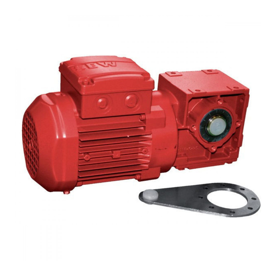
Summary of Contents for SEW-Eurodrive Spiroplan W
- Page 1 04/2000 Edition Gear Units ® R..7, F..7, K..7, S..7 Series, Spiroplan 05/2001 Operating Instructions 10503013 / EN...
- Page 2 SEW-EURODRIVE...
-
Page 3: Table Of Contents
Contents Important Notes....................4 Safety Notes ...................... 5 Gear Unit Design ....................7 Basic design of a helical gear unit ............7 Basic design of a parallel shaft helical gear unit ........8 Basic design of a helical-bevel gear unit........... 9 Base design of a helical-worm gear unit .......... -
Page 4: Important Notes
Important Notes Important Notes Safety and Please note the safety and warning notes in this publication! warning notes Electrical hazard Could result in: death or severe injuries. Imminent danger Could result in: death or severe injuries. Dangerous situation Could result in: slight or minor injuries. Damaging situation Could result in: damage of drive and operating environment. -
Page 5: Safety Notes
Safety Notes Safety Notes Preliminary The following safety notes are principally concerned with the use of gear units. remarks If using geared motors, please also refer to the safety notes for motors in the corre- sponding operating instructions. Please also take account of the supplementary safety notes in the individual chapters of these operating instructions. - Page 6 Safety Notes Setup / See notes in sections "Setup" and "Installation/Removal!" Installation Startup / Check whether the direction of rotation is correct in decoupled status (also listen out for Operation unusual grinding noises as the shaft rotates). Secure the shaft keys for test mode without output elements. Do not render monitoring and protection equipment inoperative even for test mode.
-
Page 7: Gear Unit Design
Gear Unit Design Gear Unit Design The following illustrations represent design principles. They are merely reference tools for the spare parts lists. Deviations according to gear unit size and design are possible! Basic design of a helical gear unit 03438AXX Fig.1: Basic structure of helical gear units Legend Pinion... -
Page 8: Basic Design Of A Parallel Shaft Helical Gear Unit
Gear Unit Design Basic design of a parallel shaft helical gear unit 03469AXX Fig. 2: Basic design of a parallel shaft helical gear unit Legend Pinion Gear unit housing Circlip 184 Oil seal Gear Deep groove ball bearing Disc 506 Shim Pinion shaft Tapered roller bearing Lock washer... -
Page 9: Basic Design Of A Helical-Bevel Gear Unit
Gear Unit Design Basic design of a helical-bevel gear unit 89 59 03486AXX Fig.3: Basic design of a helical-bevel gear unit Legend Pinion 25 Tapered roller bearing 102 Adhesive and sealant 523 Shim Gear 30 Tapered roller bearing 113 Wing nut 533 Shim Pinion shaft 31 Key... -
Page 10: Base Design Of A Helical-Worm Gear Unit
Gear Unit Design Base design of a helical-worm gear unit 03487AXX Fig. 4: Basic design of a helical-worm gear unit Legend Pinion Circlip Shim Gear Breather valve Circlip Shim Worm Gear unit housing Shim Worm gear Tapered roller bearing 100 Gear unit housing Shim Output shaft Tapered roller bearing... -
Page 11: Basic Design Of A Spiroplan ® Gear Unit
Gear Unit Design ® Basic design of a SPIROPLAN gear unit 03488AXX ® Fig. 5: Basic design of a SPIROPLAN gear unit Legend Pinion 19 Key Circlip Circlip Gear 22 Gear unit housing Shim Output shaft 25 Deep groove ball bearing Gear unit cover Shim 34 Deep groove ball bearing... -
Page 12: Mechanical Installation
Mechanical Installation Mechanical Installation Required tools / material • Set of spanners • Torque wrench (for shrink discs, AQ motor adapter, input shaft assembly with centering shoulder) • Mounting device • Shims and distance rings, if necessary • Fastening devices for input and output elements ®... -
Page 13: Installing The Gear Unit
Mechanical Installation Installing the gear unit The gear unit or geared motor must be mounted/installed in the specified mounting po- ® sition on a level , vibration-absorbing and torsionally rigid support structure (Spiroplan gear units are not dependent on mounting position). Do not tighten housing legs and mounting flanges against each other and pay attention to the approved overhung and axial loads Use only bolts of 8.8 quality for installation of the geared motors... - Page 14 Mechanical Installation Gear unit venting No ventilation is required for R17, R27 and F27 gear units in mounting positions M1, M3, ® M5 and M6 as well as Spiroplan W gear units. All other gear units are delivered by SEW ready for the mounting position with the breather valve and transport fixture fitted.
-
Page 15: Gear Units With Solid Shaft
Mechanical Installation Gear units with solid shaft Installation of The following illustration is an example of a moutning device for mounting couplings or input and output hubs onto gear unit or motor shaft ends. It may be possible to dispense with the thrust elements bearing on the mounting device. - Page 16 Mechanical Installation Installation of Harmonize the following factors according to the manufacturer’s recommendation when couplings installing couplings: a) maximum and minimum distance b) axial misalignment c) angular misalignment 03356AXX Fig. 6: Distance and misalignment with coupling installation Drive and output elements auch as belt pulleys, couplings, etc. must be equipped with a touchguard! ®...
-
Page 17: Installation Of Torque Arms For Shaft-Mounted Gear Units
Mechanical Installation Installation of torque arms for shaft-mounted gear units Do not strain torque arms during installation! Parallel shaft helical gear units 01029BXX Fig. 7: Torque arm for parallel shaft gear units Bushing with bearings on both ends → (1) Helical-bevel gear •... - Page 18 Mechanical Installation Bushing with bearings on both ends → (1) Helical-worm • gear units 01031CXX Fig. 9: Torque arm for helical-worm gear units ® Bushing with bearings on both ends → (1) SPIROPLAN • W gear units 02050CXX ® Fig. 10: Torque arm for SPIROPLAN W gear units ®...
-
Page 19: Installation/Removal Of Shaft-Mounted Gear Units With Key Or Splines
Mechanical Installation Installation/removal of shaft-mounted gear units with key or splines Note the construction notes in the Geared Motors catalog when designing the customer shaft! ® Installation notes 1. Apply NOCO fluid ® ® 02042BXX ® 2. Distribute NOCO fluid evenly 02043AXX 3. - Page 20 Mechanical Installation 3B: Installation with SEW installation/removal kit (→ page 22) – Customer shaft with contact shoulder 1 retaining screw 2 lock washer 3 washer 4 circlip 6 customer shaft with contact shoulder 03362BXX 3C: Installation with SEW installation/removal kit (→ page 22) –...
- Page 21 Mechanical Installation Removal notes The description applies only to gear units that were installed with the SWE mounting/ removal kit (→ page 22) (see previous description, points 3B or 3C) 1. Loosen the retaining screw 1. 2. Remove parts 2 to 4 and the spacer tube 5, if installed. 1 retaining screw 2 lock washer 3 washer...
- Page 22 Mechanical Installation SEW installation/ The SEW installation/removal kit is available with the indicated part number. removal kit 03394CXX Fig. 11: SEW installation/removal kit retaining screw locknut for removal removal washer -0.5 -0.5 -0.5 Type Part number [mm] [mm] [mm] [mm] [mm] [mm] [mm]...
-
Page 23: Installation/Removal Of Shaft-Mounted Gear Units With Shrink Disc
Mechanical Installation Installation/removal of shaft-mounted gear units with shrink disc Installation notes • Do not tighten locking screws unless shaft is installed - hollow shaft could be deformed! 1. Thoroughly remove grease from hollow 2. Degreased hollow shaft/drive shaft shaft bore and drive shaft. 01815AXX 01816AXX ®... - Page 24 Mechanical Installation 5. Tighten the locking screws by working round several times from one crew to the next (not diagonally). See table for tightening torques. 01819AXX Gear unit type Screw max. FH27 SH37 KH37...77 FH37...77 SH47...77 KH87/97 FH87/97 SH87/97 60° KH107 FH107 KH127/157...
-
Page 25: Installation Of The Am Adapter Coupling
Mechanical Installation Installation of the AM adapter coupling IEC adapters AM63 - 225 / NEMA adapters AM56 - 365 = NEMA adapters only 1 = motor shaft 04469AXX 1. Clean motor shaft and flange surfaces of motor and adapter. 2. IEC adapters: Remove motor shaft key and replace with supplied key (484). NEMA adapters: Remove motor shaft key, slide spacer tube (491) on motor shaft and install supplied key (484). - Page 26 Mechanical Installation IEC adapters AM250/AM280 1 = Motor shaft 2 = Setscrew 02047CXX 1. Clean motor shaft and flange surfaces of motor and adapter. 2. Remove motor shaft key and replace with supplied key (size AM280 only). 3. Heat coupling half (479) (to 80 °C - 100 °C) and slide on motor shaft (A = 139 mm). 4.
-
Page 27: 4.10 Installation Of The Aq Adapter Coupling
Mechanical Installation 4.10 Installation of the AQ adapter coupling 1 Motor shaft 2 Setscrew 3 Screw AQA = with keyway AQH = w/o keyway 02702CXX 1. Clean motor shaft and flange surfaces of motor and adapter. 2. AQH design: Slide spacer tube (491) on motor shaft. 3. -
Page 28: Installation On The Ad Input Shaft Assembly
Mechanical Installation 4.11 Installation on the AD input shaft assembly See section "Installation of input and output shafts" for installation of input elements. Version with Installation of motor and adjustment of motor mounting platform motor mounting platform AD../P 1 Motor mounting platform 2 Setscrew (AD6/P / AD7/P only) 3 Support (AD6/P / AD7/P only) 4 Nut... - Page 29 Mechanical Installation AD../ZR design Installing components on the input shaft assembly with centering shoulder with centering 1. The bolts must be available in the correct length to fasten the installed components. shoulder The length of the new bolts results from: l = t + a srew depth (see table) a thickness of application...
-
Page 30: Startup
Startup Startup ® Startup of helical-worm and Spiroplan W gear units Note: The direction of rotation for the output shaft has been changed from CW to CCW for helical-worm gear units S..7 series compared to the S..2 series. Switch two motor feeder cables to change the direction of rotation. -
Page 31: Troubleshooting
Troubleshooting Troubleshooting Gear unit problems Problem Possible cause Remedy Unusual, regular running Meshing/grinding noise: bearing damage Check oil (see Inspection and Maintenance), noise Knocking noise: irregularity in the gearing replace bearing Call customer service Unusual, irregular running Foreign bodies in the oil •... -
Page 32: Inspection And Maintenance
Inspection and Maintenance Inspection and Maintenance Inspection and maintenance periods Time period What to do? • every 3000 operating hours, at least every six months • Check oil • depending on operating conditions (see following • Replace mineral oil illustration), at least every three years •... -
Page 33: Inspection/Maintenance Of Gear Units
Inspection and Maintenance Inspection/maintenance of gear units Do not mix synthetic lubricants with each other nor with mineral lubricants! Mineral oil is the standard lubricant. The position of the oil level plug, oil drain plug and the breather valve is dependent on the mounting position. -
Page 34: Mounting Positions
M1 … M6 M1 … M6 Mounting Positions Mounting Positions General comments on mounting positions Mounting position designation SEW has six mounting positions M1 ... M6 for gear units (see illustration). 03203AXX Fig. 13: Mounting positions M1 ... M6 ® R..7, F..7, K..7, S..7, Spiroplan W Gear Units –... - Page 35 M1 … M6 M1 … M6 Mounting Positions Comparison The following table indicates in which way the old SEW mounting position designations old/new are integrated into the new system: R, RX R..F RF, RXF B5II B5III FA..B B6II FH..B FV..B B5II B5III KA..B...
-
Page 36: Legend For Mounting Position Pages
M1 … M6 M1 … M6 Mounting Positions Legend for mounting position pages Used symbols The following table contains all symbols used in the mounting position pages as well as their meaning: Symbol Meaning Breather valve Oil level check plug Oil drain plug Churning losses There is a possibility of increased churning losses with some mounting positions. -
Page 37: Mounting Positions, Helical Gear Units
M1 … M6 M1 … M6 Mounting Positions Mounting positions, helical gear units R17-R167 04 040 100 270° 0° 180° 90° 0° 0° 0° 0° R47-R57 0° 180° 90° 270° 270° 90° 0° 180° R17, R27 M1, M3 , M5 , M6 R47, R57 R17, R27 * →... - Page 38 M1 … M6 M1 … M6 Mounting Positions RF17-RF167 04 041 100 270° 180° 0° 90° 0° 0° RF17 0° 0° 180° 0° 90° 270° 90° 270° 0° 180° RF17, RF27 M1, M3 , M5 , M6 RF47, RF57 RF17, RF27 * →...
- Page 39 M1 … M6 M1 … M6 Mounting Positions R17F-R87F 04 042 100 270° 180° 0° 90° 0° 0° R17F 0° 0° 180° 0° R47F-R57F 270° 90° 90° 270° 0° 180° R17F, R27F M1, M3 , M5 , M6 R47F, R57F R17F, R27F * →...
- Page 40 M1 … M6 M1 … M6 Mounting Positions RX57-RX107 04 043 100 270° 0° 180° 90° 0° 0° 0° 0° 180° 0° 90° 270° 270° 90° 0° 180° * → page 36 ® R..7, F..7, K..7, S..7, Spiroplan W Gear Units – Operating Instructions...
- Page 41 M1 … M6 M1 … M6 Mounting Positions RXF57-RXF107 04 044 100 270° 180° 0° 90° 0° 0° 0° 0° 0° 180° 90° 270° 270° 90° 180° 0° * → page 36 ® R..7, F..7, K..7, S..7, Spiroplan W Gear Units – Operating Instructions...
-
Page 42: Mounting Positions, Parallel Shaft Helical Gear Units
M1 … M6 M1 … M6 Mounting Positions Mounting positions, parallel shaft helical gear units F/FA..B/FH27B-157B, FV27B-107B 42 042 100 270° 180° 0° 90° 0° 0° 0° 0° 180° 0° 270° 90° 270° 90° 0° 180° F..27 M1, M3, M5, M6 F..27 M1 - M6 F..27... - Page 43 M1 … M6 M1 … M6 Mounting Positions FF/FAF/FHF/FAZ/FHZ27-157, FVF/FVZ27-107 42 043 100 270° 180° 0° 90° 0° FF47 0° 0° 0° 0° 180° 270° 270° 90° 90° 0° 180° F..27 M1, M3, M5, M6 F..27 M1 - M6 F..27 M1, M3, M5, M6 * →...
- Page 44 M1 … M6 M1 … M6 Mounting Positions FA/FH27-157, FV27-107 42 044 100 270° 0° 180° 90° 0° FA47 0° 0° 0° 180° 0° 270° 270° 90° 90° 0° 180° F..27 M1, M3, M5, M6 F..27 M1 - M6 F..27 M1, M3, M5, M6 * →...
-
Page 45: Mounting Positions, Helical-Bevel Gear Units
M1 … M6 M1 … M6 Mounting Positions Mounting positions, helical-bevel gear units K/KA..B/KH37B-157B, KV37B-107B 34 025 100 270° 0° 180° 90° 0° 0° 0° 0° 180° 0° 90° 270° 90° 270° 180° 0° * → page 36 Caution: Note the notes in the "Geared Motors"... - Page 46 M1 … M6 M1 … M6 Mounting Positions K167-187, KH167B-187B 34 026 100 270° 180° 0° 90° 0° 0° 0° 0° 180° 0° 90° 270° 90° 270° 0° 180° * → page 36 Caution: Note the notes in the "Geared Motors" catalog, section "Project Planning Gear Units/Overhung and axial loads."...
- Page 47 M1 … M6 M1 … M6 Mounting Positions KF/KAF/KHF/KAZ/KHZ37-157, KVF/KVZ37-107 34 027 100 270° 180° 0° 90° 0° 0° KF47 0° KF47 0° 180° 0° 270° 90° 90° 270° 180° 0° * → page 36 ® R..7, F..7, K..7, S..7, Spiroplan W Gear Units –...
- Page 48 M1 … M6 M1 … M6 Mounting Positions KA/KH37-157, KV37-107 39 025 100 270° 180° 0° 90° 0° 0° KA47 0° KA47 0° 180° 0° 90° 270° 270° 90° 180° 0° * → page 36 ® R..7, F..7, K..7, S..7, Spiroplan W Gear Units –...
- Page 49 M1 … M6 M1 … M6 Mounting Positions KH167-187 39 026 100 270° 180° 0° 90° 0° 0° 0° 0° 180° 0° 90° 270° 90° 270° 0° 180° * → page 36 ® R..7, F..7, K..7, S..7, Spiroplan W Gear Units – Operating Instructions...
-
Page 50: Mounting Positions, Helical-Worm Gear Units
M1 … M6 M1 … M6 Mounting Positions Mounting positions, helical-worm gear units 05 025 100 270° 180° 0° 90° 0° 0° 0° 0° 180° 0° 270° 270° 90° 90° 0° 180° Caution: Note the notes in the "Geared Motors" catalog, section "Project Planning Gear Units/Overhung and axial loads."... - Page 51 M1 … M6 M1 … M6 Mounting Positions S47-S97 05 026 100 270° 180° 0° 90° 0° 0° 0° 0° 180° 0° 90° 270° 270° 90° 0° 180° * → page 36 Caution: Note the notes in the "Geared Motors" catalog, section "Project Planning Gear Units/Overhung and axial loads."...
- Page 52 M1 … M6 M1 … M6 Mounting Positions SF/SAF/SHF37 05 027 100 270° 0° 180° 90° 0° 0° 0° 0° 180° 0° 270° 90° 90° 270° 0° 180° ® R..7, F..7, K..7, S..7, Spiroplan W Gear Units – Operating Instructions...
- Page 53 M1 … M6 M1 … M6 Mounting Positions SF/SAF/SHF/SAZ/SHZ47-97 05 028 100 270° 180° 0° 90° 0° 0° 0° 0° 180° 0° 90° 270° 90° 270° 0° 180° * → page 36 ® R..7, F..7, K..7, S..7, Spiroplan W Gear Units – Operating Instructions...
- Page 54 M1 … M6 M1 … M6 Mounting Positions SA/SH37 28 020 100 270° 180° 0° 90° 0° 0° 0° 0° 180° 0° 270° 90° 270° 90° 180° 0° ® R..7, F..7, K..7, S..7, Spiroplan W Gear Units – Operating Instructions...
- Page 55 M1 … M6 M1 … M6 Mounting Positions SA/SH47-97 28 021 100 270° 180° 0° 90° 0° 0° 0° 0° 0° 180° 90° 270° 270° 90° 0° 180° * → page 36 ® R..7, F..7, K..7, S..7, Spiroplan W Gear Units – Operating Instructions...
-
Page 56: Lubricants
Lubricants Lubricants General SEW supplies the drives filled with a lubricant appropriate for the specific gear unit and mounting position. The decisive factor is the indicated mounting position (M1...M6, → section "Mounting positions and important order information") when ordering the drive. The lubricant fill amounts for subsequent changes in the mounting position will have to be adjusted for the specific mounting position (→... - Page 57 Lubricants Table of lubricants 01 805 692 50258AXX ® R..7, F..7, K..7, S..7, Spiroplan W Gear Units – Operating Instructions...
- Page 58 Lubricants Lubricant fill The indicated fill quantities are recommended values. The specific values vary quantities depending on number of stages and ratio. Pay close attention to the oil level plug to serve as indicator for the correct amount of oil. The following tables list the recommended values for the lubricant fill quantities in reference to mounting positions M1...M6.
- Page 59 Lubricants Parallel shaft heli- F.., FA..B, FH..B, FV..B: cal (F-) gear units Fill quantity in liters Gear units F..27 F..37 F..47 F..57 F..67 F..77 F..87 13.0 13.8 10.8 F..97 18.5 22.5 12.6 25.2 18.5 F..107 24.5 19.5 37.5 F..127 40.5 46.5 F..157 FF..:...
- Page 60 Lubricants Helical-bevel (K-) K.., KA..B, KH..B, KV..B: gear units Fill quantity in liters Gear units K..37 K..47 K..57 K..67 K..77 K..87 10.9 K..97 15.7 15.7 15.5 K..107 25.5 33.5 K..127 41.5 K..157 K..167 K..187 KF..: Fill quantity in liters Gear units KF37 KF47 KF57...
- Page 61 Lubricants ® ® Spiroplan (W-) The Spiroplan gear units always have the same fill quantity, independent of the gear units mounting position: Gear units Mounting position independent fill quantity in liters W..10 0.16 W..20 0.26 W..30 Helical-worm (S-) S..: gear units Fill quantity in liters Gear units 0.25...
-
Page 62: Address List
2, rue Denis Papin F-77390 Verneuil I’Etang Additional addresses for service in France provided on request! Argentina Assembly Buenos Aires SEW EURODRIVE ARGENTINA S.A. Tel. (3327) 45 72 84 Sales Centro Industrial Garin, Lote 35 Fax (3327) 45 72 21 Service Ruta Panamericana Km 37,5 sewar@sew-eurodrive.com.ar... - Page 63 Address list Belgium Assembly Brüssel CARON-VECTOR S.A. Tel. (010) 23 13 11 Sales Avenue Eiffel 5 Fax (010) 2313 36 Service B-1300 Wavre http://www.caron-vector.be info@caron-vector.be Brazil Production Sao Paulo SEW DO BRASIL Tel. (011) 64 60-64 33 Sales Motores-Redutores Ltda. Fax (011) 64 80 33 28 Service Rodovia Presidente Dutra, km 208...
- Page 64 Address list Finland Assembly Lahti SEW-EURODRIVE OY Tel. (3) 589 300 Sales Vesimäentie 4 Fax (3) 780 6211 Service FIN-15860 Hollola 2 Great Britain Assembly Normanton SEW-EURODRIVE Ltd. Tel. 19 24 89 38 55 Sales Beckbridge Industrial Estate Fax 19 24 89 37 02 Service P.O.
- Page 65 Address list Netherlands Assembly Rotterdam VECTOR Aandrijftechniek B.V. Tel. +31 10 44 63 700 Sales Industrieweg 175 Fax +31 10 41 55 552 Service NL-3044 AS Rotterdam http://www.vector.nu Postbus 10085 info@vector.nu NL-3004 AB Rotterdam New Zealand Assembly Auckland SEW-EURODRIVE NEW ZEALAND LTD. Tel.
- Page 66 Address list South Africa Assembly Johannesburg SEW-EURODRIVE (PROPRIETARY) LIMITED Tel. + 27 11 248 70 00 Sales Eurodrive House Fax +27 11 494 23 11 Service Cnr. Adcock Ingram and Aerodrome Roads Aeroton Ext. 2 Johannesburg 2013 P.O.Box 90004 Bertsham 2013 Capetown SEW-EURODRIVE (PROPRIETARY) LIMITED Tel.
- Page 67 Address list Additional addresses for service in the USA provided on request! Venezuela Assembly Valencia SEW-EURODRIVE Venezuela S.A. Tel. +58 (241) 8 32 98 04 Sales Av. Norte Sur No. 3, Galpon 84-319 Fax +58 (241) 8 38 62 75 Service Zona Industrial Municipal Norte sewventas@cantr.net...
- Page 68 SEW-EURODRIVE GmbH & Co · P.O. Box 3023 · D-76642 Bruchsal/Germany · Phone +49-7251-75-0 Fax +49-7251-75-1970 · http://www.sew-eurodrive.com · sew@sew-eurodrive.com...
Need help?
Do you have a question about the Spiroplan W and is the answer not in the manual?
Questions and answers
NEED PART NUMBER FOR FLANGE SEAL FOR RF167 DRN225M4 87.8482217801.0001.24.50