SEW-Eurodrive CM3C63 Addendum To The Operating Instructions
Servomotors with movilink ddi interface
Hide thumbs
Also See for CM3C63:
- Operating instructions manual (92 pages) ,
- Operating instructions manual (112 pages) ,
- Addendum to the operating instructions (60 pages)

Related Manuals for SEW-Eurodrive CM3C63


Summary of Contents for SEW-Eurodrive CM3C63
- Page 1 *26867389_0322* Drive Technology \ Drive Automation \ System Integration \ Services Addendum to the Operating Instructions ® CM3C.. Servomotors with MOVILINK DDI Interface CM3C63 – 100 Edition 03/2022 26867389/EN...
- Page 2 SEW-EURODRIVE—Driving the world...
-
Page 3: Table Of Contents
Table of contents Table of contents General information........................ 4 Motor structure ......................... 5 Basic structure ........................ 5 Motor nameplates ...................... 6 Example of the type designation.................. 7 ® Type code for MOVILINK DDI interface identification .......... 7 Designs and options ........................ 8 Synchronous servomotors .................... 8 Mechanical attachments .................... 8 Temperature sensor / temperature detection.............. 8 Encoders......................... 9... -
Page 4: General Information
CM3C.. motors are described in this document. This document is a supplement to the operating instructions "Synchronous Servomo- tors (Medium Inertia), CM3C63 – 100". The operating instructions are still valid. ® Addendum to the Operating Instructions – CM3C.. Servomotors with MOVILINK... -
Page 5: Motor Structure
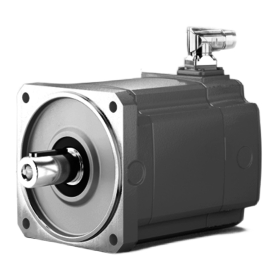
Motor structure Basic structure Motor structure Basic structure following figure shows example CM3C.. servomotor with ® MOVILINK DDI interface: 30675795851 [1] Hybrid plug connector ® Addendum to the Operating Instructions – CM3C.. Servomotors with MOVILINK DDI Interface... -
Page 6: Motor Nameplates
Motor structure Motor nameplates Motor nameplates The following figures show examples of nameplates of a CM3C.. servomotor with ® MOVILINK DDI interface: DI0E00 Jahr 2019 CM3C71L-45A-N/BK/DI/PK/AZ2Z/SD1 01.779037023.0001.19 13,2 Nm VT nN 4500r/min Mpk 39,6 Nm 7200 r/min n max 13,3 A Up 308 V 15,578 Imax 45,0 A Ta... -
Page 7: Example Of The Type Designation
Motor structure Example of the type designation Example of the type designation The following table shows the example of a type designation: Example: CM3C71L-45A-N/BK/DI/PK/AZ2Z/SD1 Synchronous servomotor CM3C71 Flange-mounted motor size 71 Length Long Rated speed and 4500 min , 400 V system voltage Shaft design Shaft without key Mechanical attachments... -
Page 8: Designs And Options
Designs and options Synchronous servomotors Designs and options Synchronous servomotors Designation CM3C.. CM3C.. series (medium inertia) 63, 71, 80, 100 Sizes S, M, L Lengths -20, -30, -45, -60 Rated speeds: -20 = 2000 min -30 = 3000 min -45 = 4500 min -60 = 6000 min A = 400 V -N, -K, -P, -E... -
Page 9: Encoders
/SDB Motor plug connector M40, socket on motor side only, hybrid plug connector for motor, brake, and communication ® MOVILINK Terminal box for CM3C63 – 100, hybrid cable for motor, brake ® and encoder MOVILINK DDI clampable ® Addendum to the Operating Instructions – CM3C.. Servomotors with MOVILINK... -
Page 10: Electrical Installation
Electrical installation Information on connector connection Electrical installation Information on connector connection With SD1 and SDB, the cable is introduced via an adjustable right-angle connector. SEW‑EURODRIVE recommends aligning the right-angle connector with the mating connector plugged in. NOTICE Damage to the right-angle connector can occur in case of rotation without mating connector. - Page 11 Electrical installation Information on connector connection INFORMATION To protect the motor protection devices or the brake control from damage, you must not route unshielded supply cables alongside switched-mode power cables. Shielded supply cables may be routed together with switched-mode power lines in one cable.
-
Page 12: Connection With Plug Connectors
Electrical installation Connection with plug connectors Connection with plug connectors The cable bushing of the power and signal cables is installed using plug connectors. Comply with the permitted bending radii of the cables. Pay attention to the combinatorics of the brake control options in chapter "Technical data" (→ 2 46). - Page 13 Electrical installation Connection with plug connectors Connection type M23, male, male thread, TE Connectivity - Intercontec Products, series 723, SEW in- sert, SpeedTec equipment, coding ring: without, protected against contact Connection diagram Contact Signal Description Motor connection phase U Motor connection phase V Motor connection phase W Brake - Brake connection -...
- Page 14 Electrical installation Connection with plug connectors Name Function Motor connection phase U Motor connection phase V Motor connection phase W GND connection 24 V 24 V DC connection Reserved Do not connect Reserved Do not connect PE connection ® MOVILINK Assignment for brakemotors with BZ.. brake Function ®...
- Page 15 Electrical installation Connection with plug connectors 4.2.2 Connecting SDB hybrid plug connectors (M40) The wiring diagram of the plug connector depicts the contact end of the connections. Assignment for motor without brake Function ® Motor connection for motors with (MOVILINK DDI) interface Connection type M40, male, male thread, TE Connectivity - Intercontec Products, series 740, SEW in-...
- Page 16 Electrical installation Connection with plug connectors Connection diagram Contact Signal Description Motor connection phase U Motor connection phase V Motor connection phase W Brake - Brake connection - Reserved Do not connect Reserved Do not connect Brake + Brake connection + Reserved Do not connect PE connection...
- Page 17 Electrical installation Connection with plug connectors Name Function Motor connection phase V Motor connection phase W GND connection 24 V 24 V DC connection Reserved Do not connect Reserved Do not connect Reserved Do not connect PE connection ® MOVILINK Assignment for brakemotors with BZ.. brake Function ®...
-
Page 18: Connecting The Plug Connectors - Single-Cable Technology With Sd1/Sdb With Brake
Electrical installation Connecting the plug connectors – single-cable technology with SD1/SDB with brake Connecting the plug connectors – single-cable technology with SD1/SDB with brake The wiring of the brake controls at the brake side is shown in the following wiring dia- grams. - Page 19 Electrical installation Connecting the plug connectors – single-cable technology with SD1/SDB with brake BS24 brake protection YE/ A VT/ D 24 V YE/ A VT/ D 24 V 35473586955 ® Addendum to the Operating Instructions – CM3C.. Servomotors with MOVILINK DDI Interface...
- Page 20 It is essential that you observe the correct polarity of the brake power supply. • Check the polarity when replacing the brake. INFORMATION ® With MOVI-C , only the connection of CM3C63.. with brake BK05 or BK06 is pos- sible. Notice: • The brakemotor cable must be shorter than 25 m. •...
- Page 21 Electrical installation Connecting the plug connectors – single-cable technology with SD1/SDB with brake BS1Z brake connection The BS1Z brake control is integrated in the motor. YE/ A OG/ B YE/ A OG/ B 35475850763 4.3.2 Wiring diagram of the brake control of the BZ.. brake Brake rectifier BMKB OG/ B...
-
Page 22: Connecting The Motor And The Encoder System With A Terminal Box
The cable entry position is specified with x, 2, 3. 9007228568088587 With motor size CM3C63.. in a fixed mounting position "x", cable entry is possible from three sides. ® Addendum to the Operating Instructions – CM3C.. Servomotors with MOVILINK... - Page 23 Maximum Maximum Maximum connection connection connection Connection Connection Connection Diameter cross sec- cross sec- cross sec- tion tion tion CM3C63 Spring ter- 4 mm Spring ter- 1.5 mm Spring ter- 1.5 mm M25×1.5 minals minals minals (3×) M20×1.5 (3×) CM3C71, M32×1.5 CM3C80, (2×)
- Page 24 Electrical installation Connecting the motor and the encoder system with a terminal box 4.4.2 Terminal assignment terminal box CM3C63 WARNING Risk of electric shock if signal cables or signal wires come into contact with power connections. Fatal or serious injuries can occur.
- Page 25 Electrical installation Connecting the motor and the encoder system with a terminal box Assignment Brake control connection BME.., Direct BMP.., brake con- BMH.., trol with Terminal [2] Type ® BMK.., MOVI-C BMV.. BS24 BS1Z.. BST, SBM, ® MOVIMOT flexible DB 00 DC 24 V BK..
- Page 26 Electrical installation Connecting the motor and the encoder system with a terminal box 4.4.3 Terminal assignment terminal box CM3C71 – 100 WARNING Risk of electric shock if signal cables or signal wires come into contact with power connections. Fatal or serious injuries can occur. •...
- Page 27 Electrical installation Connecting the motor and the encoder system with a terminal box Assignment Terminal [1] Connection Motor connection phase U Motor connection phase V Motor Motor connection phase W PE connection Assignment Brake control connection BME.., BMP.., BMH.., Terminal [2] Type BMK.., BMV..
-
Page 28: Cables For Movilink
® Cables for MOVILINK ® Cables for MOVILINK ® The MOVILINK DDI interface requires a coaxial cable for data transmission between motor and inverter. If the motor control requires a cross section of up to 10 mm , the coaxial cable is routed in a hybrid cable. -
Page 29: Hybrid Cable With Connector On The Motor Side, Open End On The Inverter Side
® Cables for MOVILINK Hybrid cable with connector on the motor side, open end on the inverter side Hybrid cable with connector on the motor side, open end on the inverter side The cable is used for the following inverters: ®... -
Page 30: Hybrid Cable With Connector On The Motor Side, Connector On The Inverter Side
® Cables for MOVILINK Hybrid cable with connector on the motor side, connector on the inverter side Hybrid cable with connector on the motor side, connector on the inverter side The cable is used for the following inverters: ® • MOVIMOT flexible with plug connector [11] - [12]... -
Page 31: Coaxial Cable With Connector On The Motor Side, Open End On The Inverter Side
® Cables for MOVILINK Coaxial cable with connector on the motor side, open end on the inverter side Coaxial cable with connector on the motor side, open end on the inverter side In the event of a cross section greater than 10 mm², the coaxial cable is required for ®... -
Page 32: Cable Tables
® Cables for MOVILINK Cable tables Cable tables Number Part num- Cross section in mm Installation type Motor Motor Inverter connec- side side tion 28123808 4 × 1.5 + 4 × 1 + coaxial Fixed installation SD1/KD1 open cable 28123816 4 ×... - Page 33 ® Cables for MOVILINK Cable tables Number Part num- Cross section in mm Installation type Motor Motor Inverter connec- side side tion [21] 28124367 4 × 1.5 + 4 × 1 + coaxial Fixed installation open cable [22] 28124375 4 × 2.5 + 4 × 1 + coaxial Fixed installation open cable...
- Page 34 ® Cables for MOVILINK Cable tables Number Part num- Cross section in mm Installation type Motor Motor Inverter connec- side side tion [41] 28129431 Coaxial cables Cable carrier in- SMCD/ open stallation SBCD/ [42] 28138376 Coaxial cables Cable carrier in- SMCD/ stallation SBCD/...
-
Page 35: Cable Connection
Cable connection Connection of motor/brake motor cable ../SD.. Cable connection Connection of motor/brake motor cable ../SD.. 6.1.1 Motor without brake Motor side Inverter side Conductor Conductor color Contact Assembly Signal Identification Description color IEC 60757 Black U/L1 Not prefabricated Motor con- nection phase U Black... - Page 36 Cable connection Connection of motor/brake motor cable ../SD.. 6.1.2 Motors with brake /BK and /BZ..D Motor side Inverter side Conductor Conductor color Contact Assembly Signal Identification Description color IEC 60757 Black U/L1 Not prefabricated Motor con- nection phase U Black V/L2 Not prefabricated Motor con- nection...
- Page 37 Cable connection Connection of motor/brake motor cable ../SD.. 6.1.3 Motors with brake /BZ Motor side Inverter side Conductor Conductor color Contact Assembly Signal Identification Description color IEC 60757 Black U/L1 Not prefabricated Motor con- nection phase U Black V/L2 Not prefabricated Motor con- nection phase V...
- Page 38 Cable connection Connection of motor/brake motor cable ../SD.. 6.1.4 Motors with brake control BS1Z Motor side Inverter side Conductor Conductor color Contact Assembly Signal Identification Description color IEC 60757 Black U/L1 Not prefabricated Motor con- nection phase U Black V/L2 Not prefabricated Motor con- nection phase V...
-
Page 39: Cable Specifications
Cable specifications Fixed installation Cable specifications Fixed installation Type LEHC 005775 LEHC 005776 LEHC 005777 LEHC 005778 LEHC 005779 Part number of bulk 28123395 28123409 28123417 28123425 28123433 cable, not prefabricated Cross section 4 × 1.5 mm 4 × 2.5 mm 4 ×... - Page 40 0.15 mm per wires, 0.15 mm wires, 0.15 mm per wires, 0.20 mm per wires, 0.20 mm optical coverage at least 85% [7] Outer cable jacket Color Orange Label SEW-EURODRIVE SEW-EURODRIVE SEW-EURODRIVE SEW-EURODRIVE SEW-EURODRIVE 28123395 28123409 28123417 28123425 28123433 4 × 1.5 + 4 × 1C + 1 4 ×...
-
Page 41: Cable Carrier Installation
Cable specifications Cable carrier installation Cable carrier installation Type LEHC 005796 LEHC 005770 LEHC 005771 LEHC 005772 LEHC 005773 LEC 005724 Part number of bulk 28123336 28123344 28123352 28123360 28123379 25672568 cable, not prefabricated Cross section 4 × 1.5 mm 4 × 2.5 mm 4 ×... - Page 42 Cable specifications Cable carrier installation Type LEHC 005796 LEHC 005770 LEHC 005771 LEHC 005772 LEHC 005773 LEC 005724 Part number of bulk 28123336 28123344 28123352 28123360 28123379 25672568 cable, not prefabricated Cross section 4 × 1.5 mm 4 × 2.5 mm 4 ×...
- Page 43 Cable specifications Cable carrier installation Type LEHC 005796 LEHC 005770 LEHC 005771 LEHC 005772 LEHC 005773 LEC 005724 Part number of bulk 28123336 28123344 28123352 28123360 28123379 25672568 cable, not prefabricated Cross section 4 × 1.5 mm 4 × 2.5 mm 4 ×...
-
Page 44: Technical Data Of Encoders
Technical data of encoders Technical data of encoders Single-turn resolution Multi-turn resolution Interface con- System data encoder option (Position resolution per (max. counter for com- nection motor revolution) plete motor revolutions) /EZ2Z ® MOVILINK DDI, 12 bit 4096 inc. – – coaxial Single-turn absolute encoder /EZ4Z... -
Page 45: Technical Data For Brake Control Bg.z, Bs.z, B
Technical data for brake control BG.Z, BS.Z, B Functional description Technical data for brake control BG.Z, BS.Z, B Functional description ® Brake controls with an extended functional scope are available in the MOVILINK DDI option portfolio. The options of the BG.Z, BS.Z and B series are brake controls which are integrated in the drive or the inverter. -
Page 46: Technical Data
Integrated in the in- Brake control instal- Motor-internal in the installation space of verter lation terminal box the encoder (B-side) Motors, motor sizes, CM3C63 – 100 CM3C63 – 100: CM3C63 – 100: brake types Nominal voltage V BZ05 – BZ5 BZ05 – BZ5 BK, BZ..D: of the brakes = 400, 230, 110 = 110 V AC... - Page 47 Technical data for brake control BG.Z, BS.Z, B Technical data BG1Z BS1Z (HV brake control) Brake control Supported brake types BZ..D Supported brake Per brake type/size: BK, BZ..D: Per brake type/size: torques maximum brake maximum brake Per brake type/size torques available as torques available as maximum brake standard...
- Page 48 Technical data for brake control BG.Z, BS.Z, B Technical data BG1Z BS1Z (HV brake control) Cable length, max- ≤ 200 m Wire cross-section ≤ 15 m imum of brake supply 1 mm BK: ≤ 40 m BZ..D: ≤ 40 m Wire cross-section of brake supply 1.5 mm BK: ≤ 60 m BZ..D: ≤ 60 m 1) Brake control only available in combination with encoder system EZ4Z or AZ4Z. 2) Brake controls B and BG.Z: Operation takes place with low voltage in accordance with IEC 60050 within the specified supply range.
- Page 52 SEW-EURODRIVE—Driving the world SEW-EURODRIVE GmbH & Co KG Ernst-Blickle-Str. 42 76646 BRUCHSAL GERMANY Tel. +49 7251 75-0 Fax +49 7251 75-1970 sew@sew-eurodrive.com www.sew-eurodrive.com...
Need help?
Do you have a question about the CM3C63 and is the answer not in the manual?
Questions and answers