Sign In
Upload
Manuals
Brands
SEW-Eurodrive Manuals
Industrial Equipment
MOVIMOT CM3C DAC Series
SEW-Eurodrive MOVIMOT CM3C DAC Series Manuals
Manuals and User Guides for SEW-Eurodrive MOVIMOT CM3C DAC Series. We have
2
SEW-Eurodrive MOVIMOT CM3C DAC Series manuals available for free PDF download: Product Manual, Operating Instructions Manual
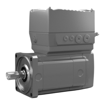
SEW-Eurodrive MOVIMOT CM3C DAC Series Product Manual (456 pages)
Drive Unit
Brand:
SEW-Eurodrive
| Category:
Industrial Equipment
| Size: 25 MB
Table of Contents
Table of Contents
3
General Information
7
About this Documentation
7
Other Applicable Documentation
7
Structure of the Safety Notes
7
Decimal Separator in Numerical Values
9
Rights to Claim under Limited Warranty
9
Recycling, Reprocessing, Reuse
9
Product Names and Trademarks
9
Copyright Notice
9
Safety Notes for MOVIMOT Performance
10
Preliminary Information
10
Duties of the User
10
Target Group
11
Security
11
Designated Use
12
Functional Safety Technology
13
Transportation/Storage
13
Creating a Safe Working Environment
15
Installation/Assembly
17
Protective Separation
17
Electrical Installation
17
Startup/Operation
17
Magnetic Fields
18
Product Description
19
System Overview of MOVI-C for Decentralized Installation
19
MOVIMOT ® Performance Drive Units at a Glance
27
Motor Assignment of MOVIMOT
29
Performance
29
Technical Data
30
General Information
30
General Technical Data of MOVIMOT Performance
31
Environmental Conditions
32
Technical Data MOVIMOT Performance
34
Electronics Data
43
Encoder
46
Interfaces
46
Technical Data - Functional Safety
48
TSM Memory Module
50
Cbg
51
USM21A Interface Adapter
58
Brake Control
59
Braking Resistors
63
Mounting Kit for Braking Resistor BW
77
Line Choke
80
Technical Data of the Brake
81
Dynastop® Torques
82
Torque Characteristic Curves
83
Surface Protection
88
Screw Fittings
90
Guard Bracket
92
Connection Cables
93
Overhung Loads
95
Mounting Positions
95
Dimension Drawings of the Drive Unit
96
Dimension Drawings of Connectors at the Electronics Cover
101
Dimension Drawings of Connectors in the Connection Box
103
Dimension Drawing of Guard Bracket
107
Project Planning for the Drive Unit
108
Preliminary Information
108
SEW-Workbench
108
Data for Drive Selection/Designation
108
Schematic Workflow for Project Planning
111
Control Mode
112
FCB Concept
117
Recommendations for Motor and Inverter Selection
125
Motor/Inverter Characteristic Curves
128
Selecting an Inverter
128
Selecting the Braking Resistor
132
Supply System Cables and Motor Cables
137
EMC-Compliant Installation According to en 61800-3
138
Line Components
138
Supply Voltage Selection
139
Energy-Saving Functions
140
MOVIMOT ® Performance
140
Dynastop - the Electrodynamic Retarding Function
153
UL-Compliant Installation
154
Project Planning for Functional Safety
156
Definitions
156
Underlying Standards
156
Integrated Safety Technology
156
Safety Requirements
161
Response Times
168
Device Structure
169
MOVIMOT® Performance Drive Unit
169
Cable Entry Position
171
Nameplate Position
173
Example Nameplate and Type Designation of the Drive Unit
174
Example of the Optional Nameplate "Electrical Regulations UL/CE
177
Examples for the Optional Nameplate "Connector Positions
177
Electronics
179
Example Nameplate and Type Designation of Electronics
183
Example Nameplate and Type Designation of Connection Unit
185
Markings
187
FS Logo Description
188
Mechanical Installation
189
Installation Notes
189
Required Tools and Resources
189
Installation Tolerances for Motor Shaft Ends
189
Tolerances for Torque Ratings
190
Installation Requirements
190
Setting up the Drive Unit
191
Tightening Torques
195
Electrical Installation
197
Installation Planning Taking EMC Aspects into Account
197
Equipotential Bonding at the Connection Box
200
Installation Instructions
201
Installation Topologies
210
MOVIMOT® Performance DAC Terminal Assignment
211
Electrical Installation - Functional Safety
215
MOVIMOT ® Performance DAC Wiring Diagram
230
Cable Routing and Cable Shielding
231
EMC Cable Glands
234
Connectors
235
Optional Connector Assignment
249
Connector Assignment at the Electronics Cover
283
PC Connection
284
Startup
292
Startup Notes
292
Startup Requirements
296
Parameterization Mode
297
Control Elements
298
DIP Switches
303
Startup with "Ex Works Parameters
307
Startup of Motors with the MOVILINK
307
DDI Interface
307
Application-Related Startup
308
Startup with MOVISUITE Engineering Software
313
10.10 Startup with the CBG21A Keypad
314
10.11 Startup with the CBG11A Keypad
317
10.12 Process Data Configuration
319
Deactivating Dynastop ® for the Startup Procedure
322
Configuring the Drive Behavior at Standstill (FCB 02, FCB 13, FCB 14)
323
Operation
324
Manual Mode with CBG22A Local Keypad
324
Manual Mode with MOVISUITE
327
Drive Unit Behavior in Case of a Voltage Failure
329
Dynastop
330
Function "Release Brake/Deactivate Dynastop
331
With FCB01
331
Dynastop® in Conjunction with STO
333
Mechanical Brake in Conjunction with STO
337
Safety
337
Service
338
Failures of the Mechanical Drive
338
Evaluating Fault Messages
340
Resetting Fault Messages
341
Fault Responses
341
Fault Messages with Parameterizable Response
342
Responses to Fault Acknowledgement
344
Description of Status and Operating Displays
346
Fault Description
352
Device Replacement
424
12.10 SEW-EURODRIVE Service
429
12.11 Shutdown
429
12.12 Storage
430
12.13 Extended Storage
430
12.14 IT Security Guidelines for Secure Waste Disposal
432
Waste Disposal
433
Inspection and Maintenance
434
Determining the Operating Hours
434
Inspection and Maintenance Intervals
435
Inspection and Maintenance Work
436
Contacting SEW-EURODRIVE
446
Index
447
Advertisement
SEW-Eurodrive MOVIMOT CM3C DAC Series Operating Instructions Manual (100 pages)
Drive Unit
Brand:
SEW-Eurodrive
| Category:
Industrial Equipment
| Size: 8 MB
Table of Contents
Table of Contents
3
General Information
5
Structure of the Safety Notes
5
Safety Notes for MOVIMOT Performance
6
Target Group
6
Designated Use
6
Functional Safety Technology
7
Transportation/Storage
8
Creating a Safe Working Environment
9
Installation/Assembly
11
Protective Separation
11
Electrical Installation
11
Startup/Operation
11
Magnetic Fields
12
Device Structure
13
Example Nameplate and Type Designation of the Drive Unit
13
Electronics
15
Example Nameplate and Type Designation of Electronics
16
Markings
18
Mechanical Installation
20
Installation Notes
20
Tolerances for Torque Ratings
20
Installation Requirements
20
Setting up the Drive Unit
21
Tightening Torques
25
Electrical Installation
27
Installation Instructions
27
MOVIMOT ® Performance DAC Terminal Assignment
36
STO Bridging Plug (3-Phase)
40
MOVIMOT ® Performance DAC Wiring Diagram
41
Cable Routing and Cable Shielding
42
EMC Cable Glands
45
Plug Connectors
46
PC Connection
53
Startup
54
Startup Notes
54
Startup Requirements
56
Parameterization Mode
57
Control Elements
58
DIP Switches
61
Startup Procedure
65
Startup with CBG22A On-Site Keypad
66
Process Data Configuration
67
Deactivating Dynastop for the Startup Procedure
70
Configuring the Drive Behavior at Standstill (FCB 02, FCB 13, FCB 14)
71
Operation
72
Drive Unit Behavior in Case of a Voltage Failure
72
Dynastop
72
Service
73
Failures of the Mechanical Drive
73
Resetting Fault Messages
75
Description of Status and Operating Displays
75
Device Replacement
80
Shutdown
83
Inspection and Maintenance
85
Inspection and Maintenance Intervals
85
Inspection and Maintenance Work
86
Advertisement
Related Products
SEW-Eurodrive CM3C63-100
SEW-Eurodrive MOVIMOT CM3C100LM
SEW-Eurodrive CMS
Sew Eurodrive MOVIMOT MM D Series
SEW-Eurodrive MOVIMOT advanced DR2C DBC Series
SEW-Eurodrive MOVIMOT RX CM3C Series
SEW-Eurodrive MOVIMOT F CM3C Series
SEW-Eurodrive MOVIMOT K CM3C Series
SEW-Eurodrive MOVIMOT S CM3C Series
SEW-Eurodrive MOVIMOT W CM3C Series
SEW-Eurodrive Categories
DC Drives
Industrial Equipment
Controller
Inverter
Engine
More SEW-Eurodrive Manuals
Login
Sign In
OR
Sign in with Facebook
Sign in with Google
Upload manual
Upload from disk
Upload from URL