Eastron SDM630 Series, SDM630-MB, SDM630-MB-2T Manual
- User manual (27 pages) ,
- User manual (26 pages) ,
- User manual (23 pages)
Advertisement
Introduction
Product Introduction
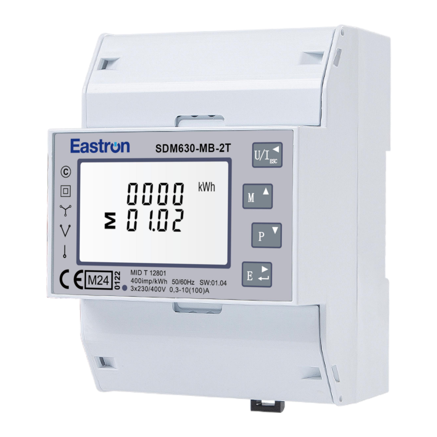
SDM630 Mbus series including models: SDM630-MB & SDM630-MB-2T.
The meter measures and displays the characteristics of single phase two wire (1p2w), three phase three wire (3p3w) and three phase four wire (3p4w) supplies, including voltage, frequency, current, power, active and reactive energy, imported or exported. Energy is measured in terms of kWh, kVArh. Maximum demand current can be measured over preset periods of up to 60 minutes.
These units are Max. 100A direct connected and do not need to connect with external current transformers(CT). An M-Bus communication port is available on the meters for remote data transmission. SDM630-MB-2T also offers a 2 tariff port for dual power source measurement.
Product Characteristics
- Bi-directional measurement IMP & EXP
- M-Bus EN13757-3
- Multi-parameters measurement
- LCD with white backlit, adjustable backlit time
Measurements:
- Phase voltage: V1, V2, V3
- Line voltage: V1-2, V2-3, V3-1
- Current: I1, I2, I3, IN
- Active power: P1, P2, P3, P_total (total active power)
- Reactive power: Q1, Q2, Q3, Q_total (total reactive power)
- Apparent power: S1, S2, S3, S_Total (total apparent power)
- Frequency: Hz
- Power factor: PF
- Active energy: Ep_imp (import active energy), Ep_exp (export active energy), Ep_total (total active energy)
- Reactive energy: Eq_imp (import reactive energy), Eq_exp (export reactive energy), Eq_total (total reactive energy)
- THD-I and THD-U
- Maximum demand: MD
Setup:
- M-Bus parameters
- Demand interval time
- Backlit time
- Supply system 1p2w, 3p3w, 3p4w
- Clear re-settable energy & demand info.
- Password modification
Technical Parameters
Technical Parameters
| Voltage AC (Un) | 3*230/400VAC |
| Voltage range | 100 - 277V AC( L-N ) |
| Voltage between phase | 100 to 480V AC ( L-L) |
| Current input | 0.3-10(100)A |
| Over current withstand | 30Imax for 0.01S |
| Frequency rating value | 50/60Hz |
| AC voltage withstand | 4KV/1min |
| Impulse voltage withstand | 6kV – 1.2/50µS waveform |
| Power consumption | ≤ 2W/10VA |
| Display | LCD with white backlit |
| Max. reading | 999999.99 kWh/kVArh |
Mechanical Characteristics
| Weight | ≈325g |
| IP Degree of Protection (IEC 60529) | IP51 front display IP20 whole meter |
| Dimensions (DxHxW) | 66*100*72mm |
| Mounting | DIN Rail 35mm |
| Material of Meter Case | Self-extinguishing UL 94 V-0 |
| Mechanical Environment | M1 |
Performance Criteria
| Operation humidity | ≤90% Non-condensing |
| Storage humidity | ≤95% Non-condensing |
| Operating temperature | -40℃~+70℃ |
| Storage temperature | -40℃~+80℃ |
| Pollution Degree | 2 |
| Altitude | ≤2000m |
| Vibration | 10Hz to 50Hz, IEC 60068-2-6 |
Electromagnetic Compatibility
| Electrostatic Discharge | IEC 61000-4-2 |
| Immunity to Radiated Fields | IEC 61000-4-3 |
| Immunity to Fast Transients | IEC 61000-4-4 |
| Immunity to Impulse Waves | IEC 61000-4-5 |
| Conducted Immunity | IEC 61000-4-6 |
| Immunity to Magnetic Fields | IEC 61000-4-8 |
| Immunity to Voltage Dips | IEC 61000-4-11 |
| Radiated Emissions | EN55032 Class B |
| Conducted Emissions | EN55032 Class B |
Safety
| Over-voltage Category | CAT III |
| Installation Category | CAT III |
| Insulating Encased Meter of Protective Class | II |
Accuracy
| Parameters | Accuracy | Resolution |
| Voltage | ±0.5% | 0.1V |
| Current | ±0.5% | 0.001A |
| Frequency | ±0.2% | 0.01Hz |
| Power Factor | ±0.01 | 0.001 |
| Active Power | ±1% | 0.001kW |
| Reactive Power | ±1% | 0.001kVAr |
| Apparent Power | ±1% | 0.001kVA |
| Active Energy | Class 1 or 0.5 IEC62053-21 Class B or C EN50470-3:2022 | 0.01kWh |
| Reactive Energy | Class 2 IEC 62053-23 | 0.01kVArh |
Outputs
M-bus Communication
The meter provides an M-Bus port for remote communication. The protocol fully comply with EN13757-3. The following communication parameters can be configured via M-bus communication:
| Baud rate | 0.6k, 1.2k, 2.4k(default), 4.8k, 9.6k bps |
| Parity | NONE/ ODD / EVEN(default) |
| Stop bits | 1 or 2 |
| M-Bus network primary address | 001 to 250 |
| M-Bus network secondary address | 00 00 00 00 to 99 99 99 99 (default: the last 8 digits of SN) |
Dual Source Measurement - 2 Tariffs
SDM630-MB-2T can measure energy from two different power supplies upon detection of a 230V voltage signal. For example, when public grid is power off and electric generator is on, the meter switches to tariff 2 measurement automatically.
The meter can also be used as a tariff meter. The tariff is controlled by an external time relay.
Pulse output
The meter is equipped with pulse output, which is fully isolated from the inside circuit. That generates pulses in proportion to the measured energy. The pulse output is polarity dependent, passive transistor output requiring an external voltage source for correct operation. For this external voltage source, the voltage shall be 5-27V DC, and the maximum input current shall be 27mA DC.
 ATTENTION: Pulse output must be fed as shown in the wiring diagram on the left.
Scrupulously respect polarities and the connection mode.
Opto-coupler with potential-free SPST-NO Contact.
Contact range: 5~27VDC
Max. current Input: 27mA DC

| Pulse outputs type | Two independent channels of optocoupler passive pulse outputs | |
| Pulse output 1 ( configurable ) | Type | kWh/kVArh ( total, imported, exported) Default: export kWh |
| Constant | dFt, 0.01, 0.1, 1, 10, 100, 1000 kWh/kVArh per imp Default: dFt = 0.0025 kWh/imp | |
| Width | 200, 100, 60mS Default: 200mS | |
| Pulse output 2 ( fixed ) | Type | Total kWh |
| Constant | 400imp/kWh | |
| Width | 100mS | |
Dimensions

Wiring Diagram
 |  |
| 3P4W | 3P3W |
 | |
| 1P2W(L+N) |
*230V/2T terminal for SDM630-MB-2T only
Terminal | Measurement Connection | Screw Connection |
| Strip Length | 12-13mm | |
| Screw | M5 | |
| Rigid/Supple | 4-25mm² | |
| Tightening Torque | 3.5Nm | |
| Model | PH2 | |
Terminal | Measurement Connection | Screw Connection |
| Strip Length | 6-7mm | |
| Screw | M2.5 | |
| Rigid/Supple | 0.5-1.5mm² (22 ~ 14AWG) | |
| Tightening Torque | 0.4Nm | |
| Model | PH0 |
Operation
Installation Display
 | The first screen lights up all display segments and can be used as a display check. |
 | The second screen and the third screen indicates the firmware installed in the unit. Note:the actual display might be different with the left on here. |
 | |
 | The interface performs a self-test and indicates the result if the test passes. |
Button Functions
| Button | Short click | Long press (3s) | ||
| Display mode | Setup mode | Display mode | Setup mode | |
 | V1 V2 V3 V1-2 V2-3 V3-1 I1 I2 I3 IN V %THD I %THD | Return to previous menu | ||
 | Hz PF PF1 PF2 PF3 MD of I1 I2 I3 MD of Power | Previous page or increase value | Primary address Second address Baud rate Parity bit Stop bit CRC All display segments | |
 | P1 P2 P3 Q1 Q2 Q3 S1 S2 S3 P-t Q-t S-t | Next page or decrease value | ||
 | Active E-t Reactive E-t Imp Active E Exp Active E Imp Reactive E Exp Reactive E | Move to right side | Enter setup mode | Confirm setting |
| Note: For tariff meters, the display is different. Please refer to the following content for detailed information. | ||||
Measurements
Voltage and current
Each successive pressing of the  button selects a new range:
 | Phase to neutral voltage (Not available under 3P3W) |
 | Phase to phase voltage (Not available under 1P2W) |
 | Current of each phase |
 | Neutral current (Not available under 3P3W &1P2W) |
 | Phase to neutral voltage THD% (Phase to phase voltage THD% under 3P3W) |
 | Phase current THD% |
Frequency, Power factor and Demand
Each successive pressing of the  button selects a new range:
 | Frequency and Power Factor (total) |
 | Power Factor of each phase (Not available under 3P3W &1P2W) |
 | Maximum current demand of each phase |
 | Maximum total power demand |
Power
Each successive pressing of the ![]() button select a new range:
button select a new range:
 | Instantaneous Active Power in kW (Not available under 3P3W &1P2W) |
 | Instantaneous Reactive Power in kVAr (Not available under 3P3W &1P2W) |
 | Instantaneous Volt-amps in kVA (Not available under 3P3W &1P2W) |
 | Total kW, kVAr, kVA |
Energy
Each successive pressing of the  button shows following measurements:
For SDM630-MB:
 | Total active energy in kWh |
 | Total reactive energy in kVArh |
 | Imported active energy in kWh |
 | Exported active energy in kWh |
 | Imported reactive energy in kVArh |
 | Exported reactive energy in kVArh |
For SDM630-Mbus-2T:
 | Total active energy in kWh |
 | Total reactive energy in kVArh |
 | T1 active energy in kWh (T1 run means under T1 calculation ) |
 | T2 active energy in kWh |
 | T1 active energy in kWh (T1 run means under T1 calculation ) |
 | T2 reactive energy in kVArh |
![]() SDM630-MB-2T shows tariff kWh/kVArh instead of imported and exported kWh/kVArh.
SDM630-MB-2T shows tariff kWh/kVArh instead of imported and exported kWh/kVArh.
Auxiliary Mode
Each successive Long pressing of the  button enter the auxiliary and each successive pressing of the
  button select a new range:
 | Primary Address |
 | Second Address |
 | Baud Rate |
 | Parity Bit |
 | Stop Bit |
 | CRC |
 | All display segments |
Setup Mode
The meter's settable parameters are password protected. Each successive Long pressing on the ![]() button to enter setup mode. Some menu items, such as password and CT, require a four-digit number entry while others, such as supply system, require selection from a number of menu options.
button to enter setup mode. Some menu items, such as password and CT, require a four-digit number entry while others, such as supply system, require selection from a number of menu options.
Menu Option Selection
- Use the
![]() and
and ![]() buttons to scroll through the different options of the set up menu.
buttons to scroll through the different options of the set up menu. - Long press
![]() to confirm your selection.
to confirm your selection. - If an item flashes, then it can be adjusted by the
![]() and
and ![]() buttons.
buttons. - Having selected an option from the current layer, long press
![]() to confirm your selection.
to confirm your selection. - Having completed a parameter setting, press
![]() to return to a higher menu level.
to return to a higher menu level.
You will be able to use the![]() and
and ![]() buttons for further menu selection.
buttons for further menu selection. - On completion of all setting-up, press
![]() repeatedly until the measurement screen is restored.
repeatedly until the measurement screen is restored.
 and
and  buttons to scroll through the different options of the set up menu.
 to confirm your selection.
 to return to a higher menu level.
Number Entry Procedure
When setting up the unit, some screens require the entering of a number. In particular, on entry to the setting up section, a password must be entered. Digits are set individually, from left to right.
The procedure is as follows:
- The current digit to be set flashes and is set using the
![]() buttons.
buttons. - Short press
![]() to confirm the digit setting and remove to the next.
to confirm the digit setting and remove to the next. - After setting the last digit, long press
![]() to confirm the setting.
to confirm the setting. - Press
![]() to return to a higher menu level.
to return to a higher menu level.
 buttons.
| Settings interface | Set status | Optional configuration |
 | Password Default: 1000 | |
 |  | Primary address setting Range: 001~250 Default: 001 |
 |  | Secondary address setting Range: 00000000 to 99999999 Default: the last 8 digits of SN |
 |  | Baud rate setting Option: 0.6k, 1.2k, 2.4k, 4.8k, 9.6k bps Default: 2.4k bps |
 |  | Parity bit setting Option: EVEN, ODD, NONE Default: EVEN |
 |  | Stop bit setting Option: 1, 2 Default: 1 |
 |  | Pulse output setting Option: kWh or kVArh (import, export, total) Default: export kWh |
 |  | Pulse rate setting Option: dFt, 0.01, 0.1, 1, 10, 100, 1000 kWh/kVArh per imp Default: dFt = 0.0025 kWh/kVArh per imp |
 |  | Pulse duration setting Option: 200, 100, 60mS Default: 100mS |
 |  | Demand interval time setting Option: 0, 5, 8, 10, 15, 20, 30, 60min Default: 60min |
 |  | Backlit time setting Option: on, off, 5, 10, 30, 60, 120 min Default: 60 min |
 |  | System type setting Option: 3P4W, 3P3W, 1P2W Default: 3P4W |
 |  | Clear Option: demand, energy |
 |  | Password setting Range: 0000~9999 Default: 1000 |
Risk Information
Information for Your Own Safety
This manual does not contain all of the safety measures operating the equipment (module, device) for different conditions and requirements. However, it does contain information which you must know for your own safety and to avoid damages. These information are highlighted by a warning triangle indicating the degree of potential danger.

This means that failure to observe the instruction can result in death, serious injury or considerable material damage.

This means hazard of electric shock and failure to take the necessary safety precautions will result in death, serious injury or considerable material damage.
Qualified personnel
Operation of the equipment (module, device) described in this manual may only be performed by qualified personnel. Qualified personnel in this manual means person who are authorized to commission, start up, ground and label devices, systems and circuits according to safety and Regulatory standards.
Proper handling
The prerequisites for perfect, reliable operation of the product are proper transport, proper storage, installation and proper operation and maintenance. When operating electrical equipment, parts of this equipment automatically carry dangerous voltages. Improper handling can therefore result in serious injuries or material damage.
- Use only insulating tools.
- Do not connect while circuit is live (hot).
- Place the meter only in dry surroundings.
- Do not mount the meter in an explosive area or expose the meter to dust, mildew and insects.
- Make sure the wires are suitable for the maximum current of this meter.
- Make sure the AC wires are connected correctly before activating the current/voltage to the meter.
- Do not touch the meter connecting clamps directly with metal, blank wire and your bare hands as you may get electrical shock.
- Make sure the protection cover is placed after installation.
- Installation, maintenance and reparation should only be done by qualified personnel.
- Never break the seals and open the front cover as this might influence the function of the meter, and will cause no warranty.
- Do not drop, or allow strong physical impact on the meter as the high precisely components inside may be damaged.
- Designed to be mounted inside of switchboards or cabinet on DIN rail.
- This device must have a suitable sized Circuit Breaker feeding the Multi Function Energy Meter so it does not exceed the maximum rated current.
- The supply wiring of this device shall be suitable sized cable to match the installed circuit breaker.
- A Disconnection Device (Circuit Breaker) should be installed close to the Multi Function Energy Meter.
- The Disconnection Device shall be marked as the Disconnection Device for the Multi Function Energy Meter.
Documents / ResourcesDownload manual
Here you can download full pdf version of manual, it may contain additional safety instructions, warranty information, FCC rules, etc.
Download Eastron SDM630 Series, SDM630-MB, SDM630-MB-2T Manual
Advertisement


Need help?
Do you have a question about the SDM630 Series and is the answer not in the manual?
Questions and answers