Advertisement
Introduction
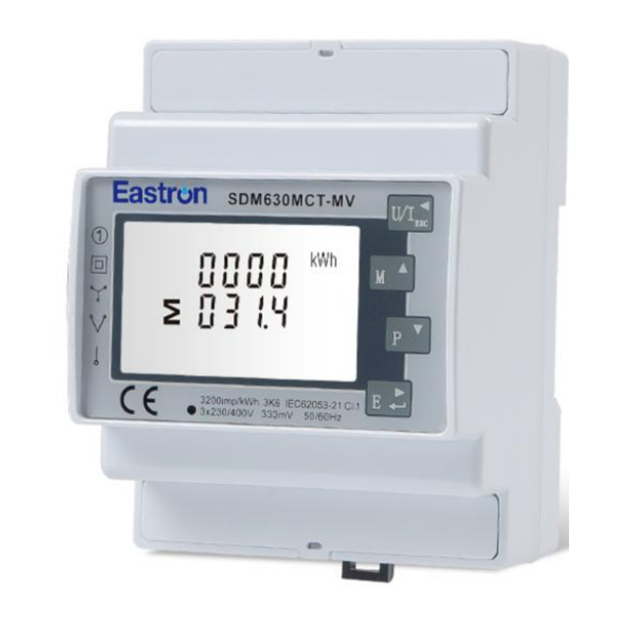
The SDM630MCT-MV measures and displays the characteristics of single phase two wire (1p2w), three phase three wire (3p3w,) and three phase four wire (3p4w) supplies, including voltage, frequency, current, power, active and reactive energy, imported or exported. Energy is measured in terms of kWh, kVArh. Maximum demand current can be measured over preset periods of up to 60 minutes. In order to measure energy, the unit requires voltage and current inputs in addition to the supply required to power the product. The requisite current input(s) are obtained via current transformers(CT).
SDM630MCT-MV can be configured to work with a wide range of CTs with 0.333V output, giving the unit a wide range of operation. Built-in interfaces provides pulse and RS485 Modbus RTU outputs. Configuration is password protected.
This unit can be powered from a separate auxiliary (AC or DC)supply. Alternatively it can be powered from the monitored supply, where appropriate.
Unit Characteristics
The Unit can measure and display:
- Line voltage and THD% (total harmonic distortion) of all phases
- Line Frequency
- Currents, Current demands and current THD% of all phases
- Power, maximum power demand and power factor
- Active energy imported and exported
- Reactive energy imported and exported
The unit has password-protected set-up screens for:
- Changing password
- Supply system selection 1p2w, 3p3w, 3p4w
- Demand Interval time
- Reset for demand measurements
- Pulse output duration
Two pulse output indicates real-time energy measurement. An RS485 output allows remote monitoring from another display or a computer.
Current Transformer Primary Current
The unit can be configured to operate with CT with 0.333V output. The secondary CT is fixed 0.333V, and the primary is optional.
RS485 Serial – Modbus RTU
This uses an RS485 serial port with Modbus RTU protocol to provide a means of remotely monitoring and controlling the Unit
Set-up screens are provided for setting up the RS485 port.
Pulse output
This provides two pulse outputs that clock up measured active and reactive energy. The constant for active energy is 3200imp/kWh (Terminals 11&12). The pulse width for pulse 1 (Terminals 9&10) can be set from the set-up menu.
Start Up Screens
| 1 |  | The first screen lights up all display segments and can be used as a display check. |
| 2 |  | The second screen indicates the firmware installed in the unit and its build number. |
| 3 |  | The interface performs a self-test and indicates the result if the test passes. |
* After a short delay, the screen will display active energy measurements.
Measurements
The buttons operate as follows:
| 1 |  | Selects the Voltage and Current display screens In Set-up Mode, this is the "Left" or "Back" button. |
| 2 |  | Select the Frequency and Power factor display screens In Set-up Mode, this is the "Up" button |
| 3 |  | Select the Power display screens In Set-up Mode, this is the "Down" button |
| 4 |  | Select the Energy display screens In Set-up mode, this is the "Enter" or "Right" button |
Voltage and Current
Each successive pressing of the  button selects a new range:
| 1-1 |  | Phase to neutral voltages (3p4w) |
| 1-2 |  | Phase to Phase voltages (3p3w) |
| 2 |  | Current on each phase |
| 2-1 |  | Neutral current |
| 3 |  | Phase to neutral voltage THD% (3p4w) |
| 4 |  | Current THD% for each phase |
Frequency and Power factor and Demand
Each successive pressing of the  button selects a new range:
| 1 |  | Frequency and Power Factor (total) |
| 2 |  | Power Factor of each phase |
| 3 |  | Maximum Current Demand |
| 4 |  | Maximum Power Demand |
Power
Each successive pressing of the  button select a new range:
| 1 |  | Instantaneous Active Power in kW |
| 2 |  | Instantaneous Reactive Power in kVAr |
| 3 |  | Instantaneous Volt-amps in KVA |
| 4 |  | Total W, VAr, VA |
Energy Measurements
Each successive pressing of the  button selects a new range:
| 1 |  | Total active energy in kWh |
| 2 |  | Total reactive energy in kVArh |
| 3 |  | Imported active energy in kWh |
| 4 |  | Exported active energy in kWh |
| 5 |  | Imported reactive energy in kVArh |
| 6 |  | Exported reactive energy in kVArh |
Setting Up
To enter set-up mode, pressing the  button for 3 seconds, until the password screen appears.

Setting up is password-protected so you must enter the correct password (default '1000') before processing.
If an incorrect password is entered, the display will show:
PASS
Err

To exit setting-up mode, press  repeatedly until the measurement screen is restored.
Set-up Entry Methods
Some menu items, such as password and CT, require a four-digit number entry while others, such as supply system, require selection from a number of menu options.
Menu Option Selection
- Use the
![]() and
and ![]() buttons to select the required item from the menu. Selection does not roll over between bottom and top of list
buttons to select the required item from the menu. Selection does not roll over between bottom and top of list - Press
![]() to confirm your selection
to confirm your selection - If an item flashes, then it can be adjusted by the
![]() and
and ![]() buttons. If not, there maybe a further layer.
buttons. If not, there maybe a further layer. - Having selected an option from the current layer, press
![]() to confirm your selection.
to confirm your selection. - Having completed a parameter setting, press
![]() to return to a higher menu level. You will be able to use the
to return to a higher menu level. You will be able to use the ![]() and
and ![]() buttons for further menu selection.
buttons for further menu selection. - On completion of all setting-up, press
![]() repeatedly until the measurement screen is restored.
repeatedly until the measurement screen is restored.
 and
and  buttons to select the required item from the menu. Selection does not roll over between bottom and top of list
 to confirm your selection
 and
and  buttons. If not, there maybe a further layer.
 to return to a higher menu level. You will be able to use the
 Number Entry Procedure
When setting up the unit, some screens require the entering of a number. In particular, on entry to the setting up section, a password must be entered. Digits are set individually, from left to right. The procedure is as follows:
- The current digit to be set flashes and is set using the
![]() and
and ![]() buttons
buttons - Press
![]() to confirm each digit setting.
to confirm each digit setting. - After setting the last digit, press
![]() to exit the number setting routine.
to exit the number setting routine.
Communication
There is a RS485 port can be used for communication using Modbus RTU protocol. For Modbus RTU, parameters are selected from front panel.
RS485 Address
(The range is from 001 to 247)

| 1 |  | From the Set-up menu, use  and and  buttons to select the Address ID buttons to select the Address ID |
| 2-1 |  | Press  button to enter the selection routine. The current setting will be flashing. button to enter the selection routine. The current setting will be flashing. |
| 2-2 |  | Use and buttons to choose Modbus Address (001 to 247) |
On completion of the entry procedure, press button to confirm the setting and press  button to return the main set-up menu. button to return the main set-up menu. | ||
Baud Rate
| 1 |  | From the Set-up menu, use and buttons to select the Baud Rate option. |
| 2-1 |  | Press  to enter the selection routine. The current setting will flash. to enter the selection routine. The current setting will flash. |
| 2-2 |  | Use  and and  buttons to choose Baud rate 2.4k. 4.8k, 9.6k, 19.2k, 38.4k buttons to choose Baud rate 2.4k. 4.8k, 9.6k, 19.2k, 38.4k |
On completion of the entry procedure, press to confirm the setting and press  to return to the main set up menu. to return to the main set up menu. | ||
Parity
| 1 |  | From the Set-up menu, use  and and  buttons to select the Parity option. buttons to select the Parity option. |
| 2-1 |  | Press  to enter the selection routine. The current setting will flash. to enter the selection routine. The current setting will flash. |
| 2-2 |  | Use  and buttons to choose Parity (EVEN / ODD/ NONE) Default is NONE. and buttons to choose Parity (EVEN / ODD/ NONE) Default is NONE. |
On completion of the entry procedure, press to confirm the setting and press  to return to the main set up menu. to return to the main set up menu. | ||
Stop bits
| 1 |  | From the Set-up menu, use and buttons to select the Stop Bit option. |
| 2-1 |  | Press  to enter the selection routine. The current setting will flash. to enter the selection routine. The current setting will flash. |
| 2-2 |  | Use and  buttons to choose Stop Bit (2 or 1) buttons to choose Stop Bit (2 or 1) |
On completion of the entry procedure, press  to confirm the setting and press to confirm the setting and press  to return to the main set up menu. to return to the main set up menu. | ||
Note: Default is 1, and only when the parity is NONE that the stop bit can be changed to 2.
CT
The CT option sets the primary current of the current transformer (CT) that wires to the meter. CT2 is fixed with 0.333V
| 1 |  | From the Set-up menu, use  and and  buttons to select the CT primary(CT1). buttons to select the CT primary(CT1).Its' default 5A,and ranged from 0005 to 9999. |
| 2 |  | Secondary CT(CT2) It's fixed 0.333V, and can not be set. |
PT
The PT option sets the secondary voltage (PT2 100 to 500V) of the Voltage transformer (PT) that wires to the meter.
| 1 |  | From the Set-up menu, use and buttons to select the PT option. The screen will show the voltage PT secondary voltage value. The default value is 400V |
| 2 |  | Secondary PT setting Press  to enter the PT secondary voltage selection routine. The range is from 100 to 500V. to enter the PT secondary voltage selection routine. The range is from 100 to 500V. |
| 3 |  | Set PT ratios value Press to enter the PT ratio screen.The range is from 0001 to 2000. |
| For example, if set the ratio to be 100, it means the primary voltage equals secondary voltage x 100 | ||
Pulse output
This option allows you to configure the pulse output. The output can be set to provide a pulse for a defined amount of energy active or reactive.
Use this section to set up the pulse output 1 — Units: Total kWh (default), Total kVArh
| 1 |  | From the Set-up menu, use  and buttons to select the Pulse output option. and buttons to select the Pulse output option. |
| 2 |  | Press  to enter the selection routine. The unit symbol will flash. to enter the selection routine. The unit symbol will flash. |
| 3 |  | Use  and buttons to choose kWh or kVArh. and buttons to choose kWh or kVArh. |
On completion of the entry procedure, press to confirm the setting and press  to return to the main set up menu. to return to the main set up menu. | ||
Pulse rate
Use this to set the energy represented by each pulse. Rate can be set to 1 pulse per 0.01kWh/0.1kWh/1kWh/10kWh/100kWh/1000kWh.

(It shows 1 impulse = 10kWh/kVArh)
| 1 | | From the Set-up menu, use and  buttons to select the Pulse Rate option. buttons to select the Pulse Rate option. |
| 2 |  | Press  to enter the selection routine. The current setting will flash. to enter the selection routine. The current setting will flash.0.01/0.1/1/10/100/1000kWh/kVArh per pulse |
Use and buttons to choose pulse rate. On Completion of the entry procedure, press  to confirm the setting and press to confirm the setting and press  to return to the main set up menu. to return to the main set up menu. | ||
Pulse Duration
The energy monitored can be active or reactive and the pulse width can be 200, 100 or 60ms.

(It shows pulse width of 200ms)
| 1-1 |  | From the Set-up menu, use and  buttons to select the Pulse width option. buttons to select the Pulse width option. |
| 1-2 |  | Press to enter the selection routine. The current setting will flash. Use and buttons to choose pulse width. |
| On completion of the entry procedure, press to confirm the setting and press to return to the main set up menu. | ||
DIT Demand Integration Time
This sets the period in minutes over which the current and power readings are integrated for maximum demand measurement. The options are: off (0), 5, 8, 10, 15,20, 30, 60 minutes
| 1 |  | From the set-up menu, use and buttons to select the DIT option. The screen will show the currently selected integration time. |
| 2-1 |  | Press to enter the selection routine. The current time interval will flash |
| 2-2 |  | Use and buttons to select the time required. |
| 2-3 |  | Press to confirm the selection. SET indicator will appear. |
| Press to exit the DIT selection routine and return to the menu. | ||
Backlit set-up
The meter provides a function to set the blue backlit lasting time.
| 1 |  | The backlit lasting time is settable Default lasting time is 60 minutes For example, if it's set as 5, the backlit will be off in 5minutes from the last time operation on the meter. Notes: If it's set as 0, the backlit will always be on. |
| 2 |  | Press to enter the selection routine. The current time interval will flash The options can be: 0/5/10/30/60/120 minutes |
| Use and buttons to select the time required. Then press to confirm the set-up. | ||
Supply System
Use this section to set the type of power supply being monitored.
| 1 |  | From the Set-up menu, use  and and  buttons to select the System option. The screen will show the currently selected power supply. buttons to select the System option. The screen will show the currently selected power supply. |
| 2 |  | Press  to enter the selection routine. The current selection will flash to enter the selection routine. The current selection will flash |
| 3-1 |  | Use and  buttons to select the required system option: 1P2(W),3P3(W),3P4(W) buttons to select the required system option: 1P2(W),3P3(W),3P4(W) |
| 3-2 |  | Press  to confirm the selection. SET indicator will appear. to confirm the selection. SET indicator will appear. |
Press  to exit the system selection routine and return to the menu. SET will disappear and you will be returned to the main Set-up Menu to exit the system selection routine and return to the menu. SET will disappear and you will be returned to the main Set-up Menu | ||
Change password
| 1 |  | Use the  and to choose the change password option and to choose the change password option |
| 2-1 |  | Press the  to enter the change password routine. The new password screen will appear with the first digit flashing to enter the change password routine. The new password screen will appear with the first digit flashing |
| 2-2 |  | Use  and and  to set the first digit and press to confirm your selection. The next digit will flash. to set the first digit and press to confirm your selection. The next digit will flash. |
| 2-3 |  | Repeat the procedure for the remaining three digits |
| 2-4 |  | After setting the last digit, SET will show. |
Press  to exit the number setting routine and return to the Set-up menu. SET will be removed to exit the number setting routine and return to the Set-up menu. SET will be removed | ||
CLR
The meter provides a function to reset the maximum demand value of current and power.
| 1 |  | From the Set-up menu, use and buttons to select the reset option. |
| 2 |  | Press to enter the selection routine. The MD will flash. |
| Press to confirm the setting and press to return to the main set up menu. | ||
Reverse connected current inputs correction set-up
| 1 |  | Use and buttons to select page "SET sys cont" |
| 2-1 |  | Press to  enter Phase A, the default is Frd (forward) enter Phase A, the default is Frd (forward) |
| 2-2 |  | Use and buttons to Phase B or C setting pages |
How to operate if phase A is reversely connected
| 1 |  | Go to phase A setting page |
| 2 |  | Press to enter the selection routine. The Frd will flash. Use button to change Frd to Rev. |
Press  to confirm the setting and press to confirm the setting and press  to return to the main set up menu. to return to the main set up menu. | ||
Specifications
Measured Parameters
The unit can monitor and display the following parameters of a single phase two wire (1p2w), three phase three wire (3p3w) or four phase four wire (3p4w) supply.
Voltage and Current
Phase to neutral voltages 100 to 289V a.c. (not for 3p3w supplies)
Voltages between phases 173 to 480V a.c. (3p supplies only)
Percentage total voltage harmonic distortion (THD%) for each phase to N ( not for 3p3w supplies)
Percentage voltage THD% between phases (three phase supplies only)
Current THD% for each phase
Power factor and Frequency and Max. Demand
Frequency in Hz
Instantaneous power:
- Power 0 to 3600 MW
- Reactive Power 0 to 3600 MVAr
- Volt-amps 0 to 3600 MVA
Maximum demanded power since last Demand reset Power factor
Maximum neutral demand current, since the last Demand reset (for three phase supplies only)
Energy Measurements
| 0 to 9999999.9 kWh |
| 0 to 9999999.9 kVArh |
| 0 to 9999999.9 kWh |
| 0 to 9999999.9 kVArh |
Measured Inputs
Voltage inputs through 4-way fixed connector with 2.5mm² stranded wire capacity. single phase two wire (1p2w), three phase three wire(3p3w) or four phase four wire (3p4w) unbalanced. Line frequency measured from L1 voltage or L3 voltage.
Three current inputs (six physical terminals) with 2.5mm² stranded wire capacity for connection of external CTs. Nominal rated input current 333mV a.c. Rms.
Maximum torque is 0.4Nm.
Accuracy
| Voltage | 0·5% of range maximum |
| Current | 0·5% of nominal |
| Frequency | 0·2% of mid-frequency |
| Power factor | 1% of unity (0.01) |
| Active power (W) | ±1% of range maximum |
| Reactive power (VAr) | ±1% of range maximum |
| Apparent power (VA) | ±1% of range maximum |
| Active energy (Wh) | Class 1 IEC 62053-21 |
| Reactive energy (VARh) | Class 2 IEC62053-23 |
| Total harmonic distortion | 1% up to 31st harmonic |
| Response time to step input | 1s, typical, to >99% of final reading, at 50 Hz. |
*Auxiliary Supply
Two-way fixed connector with 2·5mm2 stranded wire capacity.
85 to 275V a.c. 50/60Hz ±10% or 120V to 380V d.c. ±20%. Consumption < 10W.
Interfaces for External Monitoring
Three interfaces are provided: An RS485 communication channel that can be programmed for Modbus RTU protocol
- pulse output indicating real-time measured energy.(configurable)
- pulse output 3200imp/kWh (not configurable)
- The Modbus configuration (Baud rate etc.) and the pulse output assignments (kWh/kVArh) are configured through the Set-up screens.
Pulse Output
The unit provides two pulse outputs. Both pulse outputs are passive type.
Pulse output 1 is configurable. The pulse output can be set to generate pulses to represent total kWh or kVArh.
The pulse constant can be set to generate 1 pulse per:
0.01 = 10 Wh/VArh
0.1 = 100 Wh/VArh
1 = 1 kWh/kVArh
10 = 10 kWh/kVArh
100 = 100 kWh/kVArh
1000=1000 kWh/kVArh
Pulse width: 200/100(default)/60ms
Pulse output 2 is non-configurable. It is fixed up with total kWh. The constant is 3200imp/kWh.
RS485 Output for Modbus RTU
For Modbus RTU, the following RS485 communication parameters can be configured from the Set-up menu:
- Baud rate 2400, 4800, 9600, 19200, 38400
- Parity none (default)/odd/even
- Stop bits 1 or 2
- RS485 network address nnn – 3-digit number, 001 to 247
- Modbus™ Word order Hi/Lo byte order is set automatically to normal or reverse. It cannot be configured from the set-up menu.
Reference Conditions of Influence Quantities
Influence Quantities are variables that affect measurement errors to a minor degree. Accuracy is verified under nominal value (within the specified tolerance) of these conditions.
| Ambient temperature | 23°C ±1°C |
| Input frequency | 50 or 60Hz ±2% |
| Input waveform | Sinusoidal (distortion factor < 0·005) |
| Auxiliary supply voltage | Nominal ±1% |
| Auxiliary supply frequency | Nominal ±1% |
| Auxiliary supply waveform (if AC) | Sinusoidal (distortion factor < 0·05) |
| Magnetic field of external origin | Terrestrial flux |
Dimensions

Wiring Diagram
Three phase four wire

Three phase three wire

Single phase two wire

If you have any question, please feel free to contact our sales team.
Zhejiang Eastron Electronic Co., Ltd.
No.52 Dongjin Rd. Nanhu, Jiaxing, Zhejiang, 314001, China
Tel: +86-573-83698881
Email: sales@eastrongroup.com
www.eastrongroup.com
Documents / Resources
References
Download manual
Here you can download full pdf version of manual, it may contain additional safety instructions, warranty information, FCC rules, etc.
Advertisement


Need help?
Do you have a question about the SDM630MCT-MV and is the answer not in the manual?
Questions and answers