Advertisement
- 1 Introduction
- 2 Start Up Screens
- 3 Measurements
- 4 Set Up
- 5 Specifications
- 6 Dimensions
- 7 Installation
- 8 Videos
- 9 Documents / Resources
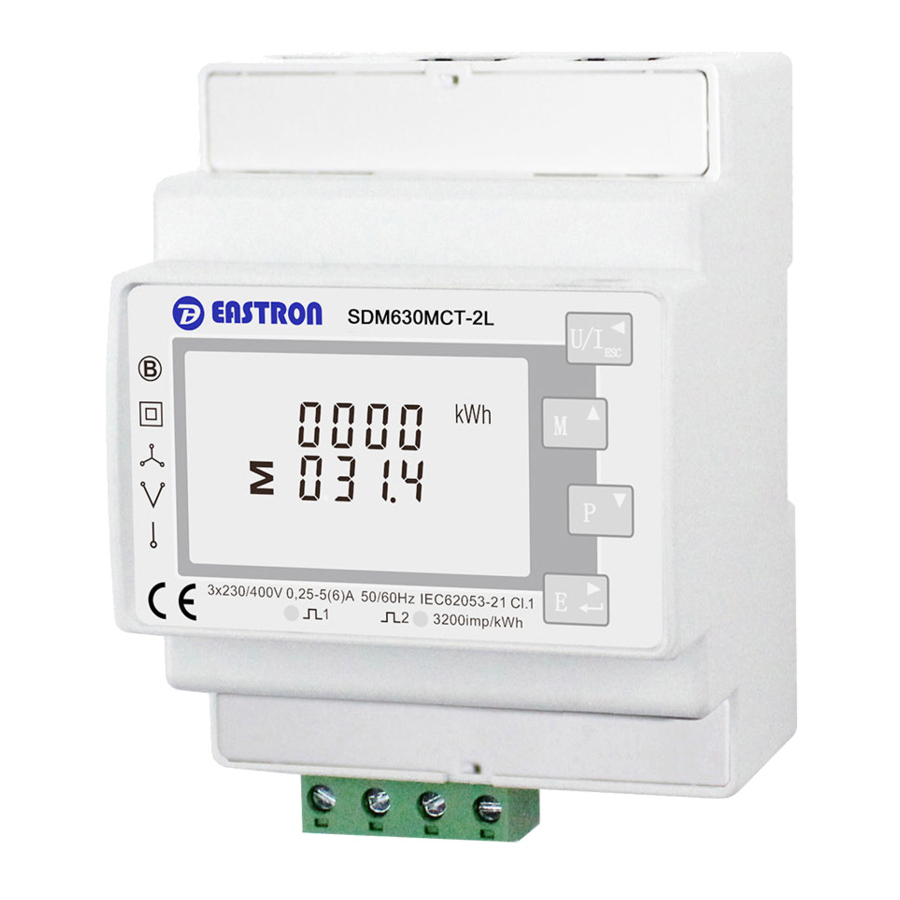
Introduction
This document provides operating, maintenance and installation instructions. This unit measures and displays the characteristics of Single Phase Two Wire (1P2W) and 2 x (C1 & C2) Three Phase Four Wire (3P4W) networks. The measuring parameters include Voltage (V), Current (A), Frequency (Hz), Power (kW/KVA/KVAr), Power Factor (PF), Imported, Exported and Total Energy (kWh/kVArh). The unit also measures Maximum Demand Current and Power, this is measured over preset periods of up to 60 minutes.
This particular model accommodates 100mA Current Transformers and can be configured to work with a wide range of CTs. It also comes with a complete comms capability with built in RS485 Modbus RTU outputs, configuration is password protected.
This unit can be powered from a separate auxiliary supply (AC or DC). Alternatively, it can be powered from the monitored supply by linking the voltage reference and neutral reference in to terminals 5 & 6 (Please refer to wiring diagram).
Unit Characteristics
The SDM630MCT-2Lcan measure and display 2 x Three Phase circuits (C1 & C2):
- Phase to Neutral Voltage and THD% (Total Harmonic Distortion) of all Phases
- Line Frequency
- Current, Maximum Demand Current and Current THD% of all Phases
- Power, Maximum Power Demand and Power Factor
- Imported, Exported & Total Active Energy
- Imported, Exported & Total Reactive Energy
The unit has a Password-Protected set up menu for:
- Changing the Password
- System Configuration - 1P2W & 3P4W.
- Demand Interval Time
- Reset for Demand Measurements
Current Transformer Primary Current
This unit requires configuring to operate with the appropriate curren transformer(s), thesecondary current is 0.1A. It is programmed by inputting the ratio (CT Primary). It can be used on primary currents up to 6000A.
RS485 Serial – Modbus RTU
This unit is compatible with remote monitoring through RS485 Modbus RTU. Set-up screens are provided for configuring the RS485 port. Refers to the "Set backlight Display" section.
Start Up Screens

*After a short delay, the screen will display active energy measurements.
Measurements
The buttons operate as follows:

Switching Three Phase Circuit Display

Voltage and Current
Each successive press of the  ESC button selects a new parameter:

Frequency and Power Factor and Demand
Each successive press of the  button selects a new range:

Power
Each successive press of the  button select a new range:

Energy Measurements
Each successive press of the  button selects a new range:


Please note the register is 9999999.9 display over two lines.
Set Up
Set up Entry Methods
Some menu items, such as Password and CT, require a fourdigit number entry while others, such as supply system, require selection from a number of menu options.
Menu Option Selection
- Use the
![]() and
and ![]() buttons to scroll through the different options of the set up menu.
buttons to scroll through the different options of the set up menu. - Hold the
![]() button for 3 seconds to confirm your selection.
button for 3 seconds to confirm your selection. - If an item flashes, then it can be adjusted by the
![]() and
and ![]() buttons.
buttons. - Having selected an option from the current layer, hold the
![]() button for 3 seconds to confirm your selection.
button for 3 seconds to confirm your selection. - Having completed a parameter setting, hold the
![]() button for 3 seconds to return to a higher menu level.
button for 3 seconds to return to a higher menu level. - On completion of all setting-up, hold the
![]() button for 3 seconds, the measurement screen will then be restored.
button for 3 seconds, the measurement screen will then be restored.
 and
and  button for 3 seconds to confirm your selection.
 and
and  buttons.
 button for 3 seconds to confirm your selection.
Number Entry Procedure
When setting up the unit, some screens require the entering of a number. In particular, on entry to the setting up section, a password must be entered. Digits are set individually, from left to right. The procedure is as follows:
- The current digit to be set flashes and then can be adjusted using the
![]() and
and ![]() buttons.
buttons. - Press the
![]() button to more right to the next digit.
button to more right to the next digit. - After setting the last digit, hold the
![]() button for 3 seconds to save your selection.
button for 3 seconds to save your selection.
 and
and Communication
The RS485 port can be used for communication using Modbus RTU Protocol. To configure the Modbus settings, such as Address and Baud Rate, this is also done within the Password-protected set up menu.
RS485 Address

Use the  and
and  buttons to choose the necessary number, then press the
  button to move along to the next number. To save the new setting, hold the button for 3 seconds until the selection stops flashing.
Baud Rate

On completion of the entry procedure, hold the button to confirm the setting.
Parity

On completion of the entry procedure, hold the button for 3 seconds until the selection stops flashing.
Stop bits

On completion of the entry procedure, hold the button for 3 seconds until the selection stops flashing.
CT Configuration
This unit is CT Operated, the primary (CT1) and secondary (CT2) of the current transformer need to be programmed correctly for the meter to scale the inputs accordingly.

The CT Rate is the primary rate/ratio of the CT.
For Example: 200/100mA Current Transformers, so the CT Rate would be 0200 and the CT2 would be 0.1A.
PT
The PT option sets the Secondary Voltage (PT2 100-500V) of the Voltage Transformer (PT) that may be connected to the meter.

The PT Rate is the PT Primary divided by the PT Secondary. For Example: Voltage Transformer - 11000÷110=100, so the PT Rate would be 0100 and the PT2 would be 110.
DIT (Demand Integration Time)
This sets the period (in minutes) in which the Current and Power readings are integrated for maximum demand measurement. The options are off; 5; 10; 15; 30 or 60 minutes.

Hold the button for 3 seconds to exit the set up menu.
Set backlight Display
The meter provides a function to set how long you want the display screen back light to be active

Hold the button to confirm the setting and press  to return to the main set up menu.
Supply System
The unit has a default setting of 3 Phase 4 Wire (3P4W).
Use this section to set the type of electrical system. button for 3 seconds to exit the set up menu.

Hold the button to confirm your adjustment. Hold the  button for 3 seconds to exit the set up menu.
CLR
The meter provides a function to reset the maximum demand value of current and power.

Hold the button to confirm the setting and press  to return to the main set up menu.
Change Password

Hold the  button for 3 seconds to exit the set up menu.
P1 & P2 Reversal
If P1 is facing the load not the supply you need to reverse the flow direction though the "Set System Continued" menu:

Hold the  button for 3 seconds to exit the set up menu
System Phase Sequence
The system sequence option sets the phase sequence with the voltage V1,V2 & V3 of the meter

Specifications
Measured Parameters
The unit can monitor and display the following parameters of a Single Phase Two Wire (1P2W) or Three Phase Four Wire (3P4W) system.
Voltage and Current
- Phase to Neutral Voltages 100-289V AC
(not for 3P3W supplies). - Phase to Phase Voltages 173-500V AC
(3 Phase supplies only). - Percentage Total Voltage Harmonic Distortion (V %THD) for each Phase to Neutral (not for 3P3W supplies).
- Percentage Total Voltage Harmonic Distortion (V% THD) between Phases (3 Phase supplies only).
- Current %THD for each Phase.
Power factor and Frequency and Max. Demand
- Frequency in Hz• Instantaneous power:
- Power 0-3600 MW
- Reactive power 0-3600 MVAr
- Volt-amps 0-3600 MVA
- Maximum Demand Power since last reset
- Power factor
- Maximum Neutral Demand Current, since the last reset (for Three Phase supplies only)
Energy Measurements
| 0 to 9999999.9 kWh |
| 0 to 9999999.9 kVArh |
| 0 to 9999999.9 kWh |
| 0 to 9999999.9 kVArh |
Measured Inputs
Voltage inputs through 4-way fixed connector with 2.5mm² stranded wire capacity. Single Phase Two Wire (1P2W)OR Three Phase Four Wire (3P4W) unbalanced. Line frequency measured from L1 Voltage or L3 Voltage. Three current inputs (six physical terminals) with 2.5mm² stranded wire capacity for connection of external CTs. Nominal rated input current 0.1A AC RMS.
Accuracy
| 0·5% of range maximum |
| 0·5% of nominal |
| 0·2% of mid-frequency |
| 1% of unity (0.01) |
| ±1% of range maximum |
| ±1% of range maximum |
| ±1% of range maximum |
| Class 1 IEC 62053-21 |
| ±1% of range maximum |
| 1% up to 31st harmonic |
| 1s, typical, to >99% of final reading, at 50 Hz. |
Auxiliary Supply
This unit does not require a separate auxiliary supply; the unit is self supplied it draws the necessary power from the voltage input connections. If a three phase supply is connected, and the phase that is powering the unit fails, it will change the phase supply to avoid shutting down.
Interfaces for External Monitoring
Three interfaces are provided:
- RS485 communication channel that can be programmed for Modbus RTU protocol
The Modbus configuration (baud rate etc.) and the pulse relay output assignments (kW/kVArh) are configured through the set-up screens.
RS485 Output for Modbus RTU
For Modbus RTU, the following RS485 communication parameters can be configured from the set-up menu:
Baud rate: 2400, 4800, 9600, 19200, 38400
Parity: none (default) / odd / even
Stop bits: 1 or 2
RS485 Network Address: 3 digit number - 001-247
Modbus™ Word order Hi/Lo byte order is set automatically to normal or reverse. It cannot be configured from the set-up menu.
Reference Conditions of Influence Quantities
Influence Quantities are variables that affect measurement errors to a minor degree. Accuracy is verified under nominal value (within the specified tolerance) of these conditions.
| 23°C ±1°C |
| 50 or 60Hz ±2% |
| Sinusoidal (distortion factor < 0·005) |
| Nominal ±1% |
| Nominal ±1% |
| Sinusoidal (distortion factor < 0·05) |
| Terrestrial flux |
Environment
| -25°C to +55°C* |
| -40°C to +70°C* |
| 0 to 95%, non-condensing |
| Up to 3000m |
| 1 minute |
| 10Hz to 50Hz, IEC 60068-2-6, 2g |
| 30g in 3 planes |
*Maximum operating and storage temperatures are in the context of typical daily and seasonal variation.
Mechanics
| 72 x 94.5 mm (WxH) per DIN 43880 |
| DIN rail (DIN 43880) |
| IP51 indoor |
| Self-extinguishing UL 94 V-0 |
Dimensions

Installation
Wiring Three Phase Four Wire

CT Orientation
With this meter the CT can be installed one of four ways depending in which way, will determine on the phase sequence of the meter
Option1 Default
")
Option 2
Requires phase sequence, change L3 to L1 and L1 to L3, please refer to the "System Phase Sequence" section.

Option 3
Requires flow reversal, please refer to the "P1 & P2 Reversal" section

Option 4
Requires phase sequence change L3 to L1 and L1 to L3 please refer to the "System Phase Sequence" section and CT reversal, please refer to the "P1 & P2 Reversal" section


VideosEastron Easy Click SDM630MCT-2L Video by Eastron Europe Ltd
Documents / ResourcesDownload manual
Here you can download full pdf version of manual, it may contain additional safety instructions, warranty information, FCC rules, etc.
Advertisement


Need help?
Do you have a question about the SDM630MCT-2L and is the answer not in the manual?
Questions and answers