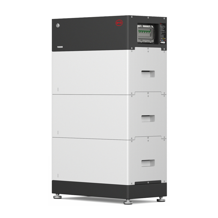
BYD HVS 5.1, HVS 7.7, HVS 10.2, HVS 12.8 Manual
- Quick start manual (62 pages) ,
- Operating manual (60 pages) ,
- Manual (16 pages)
Advertisement
- 1 GENERAL STEPS
-
2
ERROR ANALYSIS
- 2.1 BCU shows no reaction / No LED
- 2.2 BCU switch cannot be flipped up / LED remains on
- 2.3 Problem with the Firmware Update / App Configuration / Battery Wi-Fi
- 2.4 Battery inverter communication / no charging or discharging
- 2.5 SOC & charging logic
- 2.6 Unexpected shutdown
- 2.7 Module Extension / Parallel connection
- 2.8 Be Connect Plus (BCP)
- 2.9 LED event code (EC)
- 2.10 Voltage measurement and undervoltage
- 2.11 Identifying a faulty module / Module exclusion method
- 3 SERVICE TASKS
- 4 Documents / Resources
GENERAL STEPS
Always make sure to use the latest version of this service document, available at: www.bydbatterybox.com
Please proceed first with the installation steps by:
| No. | Name | Description |
| 1 | Con figuration | Check if the configuration is correct. Refer to the latest "BYD Battery-Box Premium HVS & HVM Compatible Inverter List" (V2.19 or above) available at: www.bydbatterybox.com Make sure the inverter is configured correctly. |
| 2 | Only HVS or HVM | Do not mix up HVS-modules ("I") with HVM-modules ("II"). |
| 3 | External connections | 
|
| 4 | Latest firmware | Always install / update the latest firmware (also use the latest app version). Note: If not stated otherwise, the default Wi-Fi password is BYDB-Box. |
| 5 | App configuration | To complete the commissioning, the configuration of the battery via "BYD Be Connect 2.0" app or "BYD Be Connect Plus" (BCP) tool for PC is mandatory. |
| 6 | Proper restart | NOTE: It is important that the battery is switched on before the inverter! Else, the BCU might not start and not show any reaction (no LED, no Wi-Fi). Defined restart (mind the sequence)
|
| 7 | Check the correct operation | The system runs properly if:
|
ERROR ANALYSIS
BCU shows no reaction / No LED
LED does not light up, although the system is switched on.
| No. | Name | Description |
| 8 | Module quantity | Check if the module quantity fulfills the minimum requirement (HVS: 2, HVM: 3 modules) and check the "Compatible Inverter List" for inverter requirements. |
| 9 | Voltage measurement | ( Make sure the voltage of the battery tower is higher than 120V.) |
| 10 | Follow the sequence correctly | NOTE: It is important that the battery is switched on before the inverter! Else, the BCU might not start and not show any reaction (no LED, no Wi-Fi). See following:
|
| 11 | Only LED off? | Check if there is a Wi-Fi access point of the Battery-Box. If so, only the external LED is inactive, but commissioning could still work. In that case make sure that the internal cable of the LED is connected properly. |
| 12 | BCU exchange | Only if voltage looks good: Test another BCU, if available. |
BCU switch cannot be flipped up / LED remains on
The system switches off immediately (within 5 seconds) / LED remains on even though the system switch is off.
| No. | Name | Description |
| 13 | Switch was flipped down by hand | If the switch was flipped down manually, then it cannot be flipped up again within 10 10 minutes. ( Please refer to the manual for the correct switch-off procedure.) |
| 14 | Steady blue LED? EC102? (1 xwhite, 2 xblue) | Try to properly shut down the BCU ( press the LED button for more than 5 seconds ).
|
| 15 | BCU exchange | Only if the voltage looks good: Test another BCU, if available. |
Problem with the Firmware Update / App Configuration / Battery Wi-Fi
The BCU consists of two components: the BMU and the BMS. The firmware update from the app will update the BMU, which will then update the BMS. The BMS will only be updated once there is communication between the battery and the inverter or immediately after the app configuration. It can take up to 20 minutes for the firmware to be updated on the BMS .
| No | Name | Description |
| 16 | Correct app and firmware | Make sure to have the latest app version (> 2.3.16) and battery firmware ( downloadable in the app) on your mobile device before connecting the app with the battery Wi-Fi. If the app cannot be installed, or if other general problems occur with the app:
|
| 17 | Wi-Fi cannot be found / Wi-Fi unstable | The battery Wi-Fi turns off 5 hours after the battery is activated. To reactivate the Wi-Fi, press the LED button about 1 second or restart the system. To reset the Wi-Fi, press the LED button three times 1 second within 6 seconds. If the problem remains:
|
| 18 | BMS version not updated | The app will only update the BMU. The BMU will automatically update the BMS, once the BMU is updated and the inverter communication is established correctly or right after the configuration is done. The BMS update can take about 20 minutes. If the BMS version is not updated after 20 minutes with stable inverter communication, follow the process below:
|
Battery <> inverter communication / no charging or discharging
| No. | Name | Description |
| 19 | Configuration | Check if the configuration is correct. Refer to the latest "BYD Battery-Box Premium HVS &HVM Compatible Inverter List" (V2.19 or above) available at: www.bydbatterybox.com Make sure the inverter is configured correctly. |
| 20 | App configuration and firmware | Please check if the app configuration has successfully done and the firmware is the most recent one. If there are problems, please refer to Problem with the Firmware Update / App Configuration / Battery Wi-Fi Section |
| 21 | Check terminal resistor | If only one tower is installed, a terminal resistor should be plugged into the "IN" port. If two or three towers are connected in parallel, a terminal resistor should be plugged into the "IN" port of the last slave tower. |
| 22 | Communication connection | Does the inverter properly detect the battery? Check if the inverter detects the battery parameters (e.g., SOC, battery temperature) correctly. If not, check the cabling:
|
| 23 | Grounding | Connect Battery-Box directly to the ground bus of the house (do not connect it over the inverter casing or other devices). Proper grounding of the battery is essential for trouble-free and secure data transmission. |
| 24 | Battery relay closed? / output voltage available? | Once communication has been established between battery and inverter, the BCU is supposed to close the relay. Only then there will be output voltage. Therefore please check if output voltage is present. You can check this either by Be Connect 2.0 app / Be Connect Plus tool or by checking if the inverter correctly shows the battery voltage. |
| 25 | Restart the system | Defined restart (mind the sequence)
|
SOC & charging logic
| No | Name | Description |
| 26 | SOC at commissioning | New HVS / HVM modules are delivered with a 30% SOC, while a new BCU might show a different SOC at the beginning (mostly 50% / 30% / 0%). The latter one should be understood as a placeholder value, since a new BCU cannot measure the SOC of modules. As soon as the system starts to run (charging/discharging) the SOC detection will be gradually corrected. The SOC calibration is completed at the latest after a full cycle. |
| 27 | SOC jumps | The SOC of an LFP battery cannot be measured; it is a calculated value. In general, the state of charge (SOC) of a battery is calculated using the voltage, but other factors such as temperature, current flow and charging behavior also play a role. The calculation of the SOC is generally more precise when the battery regularly undergoes full cycles. Every now and then an SOC correction / calibration may occur. If there are other questions, please contact the service team. |
Unexpected shutdown
The system has been successfully commissioned in the past and has run for some time. Later on an unexpected shutdown occurred.
| No | Name | Description |
| 28 | Inverter communication | The battery only works with a compatible external inverter. If, for any reason, the communication between the battery and inverter is lost, the battery will shut down automatically within 30 minutes. Therefore, check which one shut down first (battery or inverter) and check if inverter is properly detecting battery (e.g,. showing correct SOC or temperature). If communication problem remains |
| 29 | Battery logs / History data | Sporadic alarms are hard to detect as they only occur sometimes. Therefore, it is very important to download and provide all the historic battery log files in order to identify the root cause. |
| 30 | Inverter warning & monitoring | An unexpected shutdown can be caused by overall system settings. Therefore, it is necessary to evaluate inverter data as well.
|
Module Extension / Parallel connection
| No | Name | Description |
| 31 | Extension | Note: It is important that all modules of a storage tower have a similar SOC (tolerance: 5%). Within 5 days before extension, it is recommended to fully charge the existing battery system to 100% SOC at least once. New modules have about 30% SOC. Therefore, please ensure that the SOC of the original system is between 25% and 35% before adding a new module. Don't forget to adjust the number of modules in the configuration if necessary. If the 30% SOC rule is not followed, temporary capacity loss and SOC jumps might occur. In such cases, a charger may be required to align the SOC of the modules. Please contact your local service provider for assistance. |
| 32 | Parallel connection | Cabling / installation (including parallel connection) is described in the short installation guide. Here are some notes:
|


Be Connect Plus (BCP)
Be Connect Plus is a PC tool. With Be Connect Plus (BCP) you can:
- Read battery information
- Configure the battery system
- Update BMU & BMS firmware
- Export / download battery logs
BCP is constantly being improved and updated. Make sure to use the latest program version. You can download the latest version of the tool at www.bydbatterybox.com / www.eft-systems.de / www.alpspower.com.au .
For analysis, please download and provide the data/logs as described in the program instructions (see PDF manual included).
Note: You need a computer with Windows that will be connected to the battery Wi-Fi.
Log in as Installer to Be Connect Plus. The default password for the battery Wi-Fi is the same: BYDB-Box
")
LED event code (EC)
A steady white LED indicates standby mode, while a blinking white LED means charging or discharging.
During battery initialization, the LED will flash white and blue with an interval time of 0.5 seconds (normal during startup). When the LED flashes blue with an interval time of 1 second, it indicates an event code. Please start to count when the white LED begins to flash, and then record how many times white and blue LED flashes (also refer to the manual for details). Examples:
1xwhite, 3xblue → EC 103
1xwhite, 11xblue → EC 111
3xwhite, 3xblue → EC 303
Most errors are caused by faulty communication, incorrect app configuration or a missing battery restart after the app or BCP configuration.
Note: If the battery is not correctly configured with the app, the event code (EC) might be misleading.
| Event Code (EC) | Measure | ||
| EC 101 | DC cable reverse connection / DC short-circuit
| ||
| EC 102 | Abnormal shutdown / PreCharge failure/ Module failure
| ||
| EC 103 | Voltage Sensor Failure / BIC Communication Failure
| ||
| EC 104 | Faulty temperature sensor
| ||
| EC 105 | Pack Voltage Sensor Failure
If the problem remains:
| ||
| EC 203 EC 303 EC 403 EC 503 EC 603 EC 703 EC 803 | Incorrect module quantity / Module not detected
| ||
| EC 106 | Current Sensor Failure
If the problem remains:
| ||
| EC 107 | Cell failure or voltage difference alarm(level 3)
| ||
| EC 108 | PreCharge Fault
If the problem remains:
| ||
| EC 109 | BIC balancing failed Make sure that the latest firmware is installed and that the battery has been properly restarted. If the problem remains: it is probably caused by a module. Follow the "Module exclusion method". | ||
| EC 110 | Low voltage The system needs to be charged very soon and should not be further discharged.
| ||
| EC 111 | Normal when the battery has just started.
Please also make sure the terminal resistor is plugged in a correct position. Refer to the Manual. If EC111 remains even after the inverter detects battery and even after redoing app configuration, test another BCU if available. | ||
| EC 112 | No communication with inverter. Check inverter communication | ||
Voltage measurement and undervoltage
 ATTENTION: High voltage!
You can see the max. and min. cell voltage in the Be Connect 2.0 app. You can also get the detailed module and cell voltage in the BCP Program or measure it manually according to the description below:
Measurement of Tower Voltage
Remove the BCU and measure the tower voltage on the topmost module as shown below.
Note: The nominal voltage should be the module quantity times 100V (for HVS) or the module quantity times 50V (for HVM ).


Undervoltage
A module in which one of the 32 (HVS) / 16 (HVM) cells has a voltage of <1.5 V is considered to be in undervoltage (check with BCP / Be C onnect 2.0 if possible).
A HVS module with >90 V and a HVM module with >45 V should be fine, and you can continue to check other items according to this service guideline. Always make sure the firmware is the latest. If the module voltage is <90V (HVS) / <45V (HVM) but the single cell voltage is >1.5V, the battery needs to be charged quickly(follow the instructions of EC110 in ).
- If only one module is in undervoltage: Remove that one and try to start the system without it (if the remaining modules still comply with the minimum quantity requirement). Otherwise, avoid further discharge (e.g., remove the BCU)
- If one or all modules are in undervoltage: Contact the service team as stated below and make sure to avoid any further discharge of the battery (e.g remove BCU from the system)
When contacting the service team, make sure to fill out the service checklist completely and provide the following information:
- Serial Numbers (of the BCU and all affected modules)
- Tower voltage and individual module voltages of all modules (related to serial number)
- What was the status of the system switch on the BCU when the undervoltage (UV) happened? (tripped or not) - If possible: Logs from the battery using BCP and screenshots showing the cell voltages
- Initial firmware version of the battery when the undervoltage happened (BMU and BMS)
- Inform if the BCU could shut down normally by pressing the LED button. (Note: if you have updated the firmware version after undervoltage, write down whether the battery could be switched off manually before the firmware update.)
- Detailed description of how and why the system reached undervoltage if known. Include the information of when the system was installed and commissioned and in which circumstance and when the undervoltage happened. If the battery was never running before: Why did it never work before, and what was the battery's status when the battery
was left (on / off / LED) - Inverter model, serial number and inverter logs
- Access to the inverter portal (addinfo@eft-systems.de and provide the name of the system in the portal)
Identifying a faulty module / Module exclusion method
The module quantity must be adjusted in the app whenever the number of modules is changed!
- Install the Battery-Box system complying with the minimum quantity requirement (HVS: 2 modules, HVM: 3 modules).
- Check System. If Okay , add one module at a time, adjust the module number in the app and check again
![]()
![]()


SERVICE TASKS
Please go through the general steps beforehand.
BCU replacement
Have you detected a faulty BCU?
After replacing the BCU, please remember to redo the configuration and firmware-update with the app or BCP.
Module Replacement
Have you detected a faulty module?
In the meantime, you can continue to use the battery system with the remaining modules and a correspondingly reduced capacity (taking into account the minimum number of modules).
Please note: It is important that all modules of a battery tower have a similar state of charge (SOC) with a tolerance of 5%. New modules have about 30 % SOC. If the remaining modules have not yet been put into operation (not charged / discharged), the new module can be easily added. Otherwise, it is basically a module extension. In this case, please add the new module to the system only when the SOC of the system is between
25% and 35% ( see extension process in the O perating M anual). Make sure to configure c orrectly after any change to the module quantity.

Documents / Resources
References
![www.bydbatterybox.com]() BYD Battery-Box – BYD Battery-Box
BYD Battery-Box – BYD Battery-BoxEft-Systems
![www.alpspower.com.au]() ALPS POWER PTY LTD – BYD Battery-Box Australia Authorized Partner
ALPS POWER PTY LTD – BYD Battery-Box Australia Authorized Partner

Download manual
Here you can download full pdf version of manual, it may contain additional safety instructions, warranty information, FCC rules, etc.
Advertisement


Need help?
Do you have a question about the HVS 5.1 and is the answer not in the manual?
Questions and answers