Table of Contents
Advertisement
Quick Links
Advertisement
Table of Contents

Related Manuals for BYD HVS 5.1


Summary of Contents for BYD HVS 5.1
-
Page 2: Legal Provisions
Shenzhen BYD Electronic Co., LTD Legal Provisions Legal Provisions All the information in this document is the property of Shenzhen BYD Electronic Co., LTD. No part of this document could be reproduced in any way for business use. Internal use is allowed. -
Page 3: Table Of Contents
Contents Legal Provisions ............................1 Information on this Document ......................5 1.1. Validity ............................5 1.2. Target Group ..........................5 1.3. Content and Structure of this Document ................5 1.4. Declaration of Conformity ..................... 5 1.5. Levels of Warning Messages ....................5 1.6. - Page 4 5.1.3. Safety Gear ........................18 5.1.4. Additionally Required Installation Material ............18 5.2. Installation ..........................19 Electrical Connection ........................21 6.1. Overview of the Connection Area ..................21 6.2. Connection Diagram ......................23 6.2.1. One Battery System ....................23 6.2.2. Two Battery Systems ....................24 6.2.3.
- Page 5 11.1. Battery System Behavior under Fault Conditions ............41 11.2. LED Light Designation for Errors ..................41 12. Maintenance and Storage ....................... 43 13. Disposal of the Battery System ...................... 44 14. Technical Data ..........................45 15. Contact Information ........................47 Appendix Connection Options with Inverters ..................
-
Page 6: Information On This Document
1 Information on this Document 1. Information on this Document 1.1. Validity This document is valid for the Battery-Box Premium HVS 5.1, 7.7, 10.2, 12.8, and HVM 8.3, 11.0, 13.8, 16.6, 19.3, 22.1 from firmware version BMU 3.16, BMS 3.24. 1.2. Target Group... -
Page 7: Symbols In The Document
1 Information on this Document Shenzhen BYD Electronic Co., LTD CAUTION Indicates a hazardous situation which, could result in minor or moderate injury. NOTICE Indicates a situation which, if not avoided, can result in property damage. 1.6. Symbols in the Document Sections describing activities to be performed by qualified persons only. -
Page 8: Safety
Alterations to the battery system, e.g., changes or modifications are not allowed unless the written permission of BYD is achieved. Unauthorized alterations will void the guarantee and warranty claims. BYD shall not be held liable for any damage caused by such changes. The type label should always be attached to the battery system. -
Page 9: Firefighting Measures
2 Safety Shenzhen BYD Electronic Co., LTD 2.2.2. Firefighting Measures The battery modules may catch fire when it is put into the fire. In case of a fire, please make sure that an ABC or carbon dioxide extinguisher is nearby. Water cannot be used to extinguish the fire. -
Page 10: Warning Of Electric Shock
Shenzhen BYD Electronic Co., LTD 2 Safety 2.2.4. Warning of Electric Shock DANGER Danger to life due to electric shock when live components or DC cables are touched The DC cables connected to an inverter may be live. Touching live DC cables results in death or serious injury due to electric shock. -
Page 11: Notice Of Property Damage
NOTICE Damage to the battery system due to under voltages If the battery system doesn`t start at all, please contact BYD local after-sales • service within 48 hours. Otherwise, the battery could be permanently damaged. HVS&HVM Operating Manual... -
Page 12: Scope Of Delivery
Shenzhen BYD Electronic Co., LTD 3 Scope of Delivery 3. Scope of Delivery BCU and Base Package M4x14 Countersunk Screw Base Hanger (PDU Part) Documents Hanger (Wall Part) M5 Screw M6 Bolt and Nut Battery Module Package M4x14 Countersunk Screw... -
Page 13: Battery System Overview
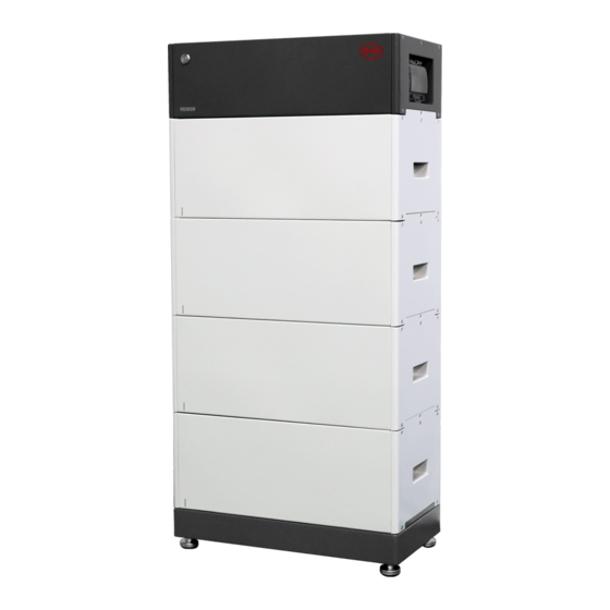
4 Battery System Overview Shenzhen BYD Electronic Co., LTD 4. Battery System Overview 4.1. Battery System Description The Battery-Box Premium HVS&HVM is used as a connected battery for the intermediate storage of excess PV energy in an inverter system. Battery Module... -
Page 14: Interface
Shenzhen BYD Electronic Co., LTD 4 Battery System Overview ≤ ≤5 ≤ ≤8 Maximum three battery systems could be connected in parallel. (This restriction does not apply for parallel connection with SMA Sunny Boy Storage 3.7-6.0. Please check the inverter operation manual on how to connect up to three batteries.) -
Page 15: Symbols On The System
Internet, it will join the Be Connect Monitoring. Be Connect Monitoring is a platform that BYD service could diagnose the battery system and update firmware remotely for customers. It is highly recommended you to make the Internet connection available to have a better service. - Page 16 Shenzhen BYD Electronic Co., LTD 4 Battery System Overview Beware of electrical voltage . Beware of a danger zone This symbol indicates that the system must be additionally grounded if additional grounding or equipotential bonding is required at the installation site.
-
Page 17: Led Signals
4 Battery System Overview Shenzhen BYD Electronic Co., LTD 4.4. LED Signals Flashing white 0.5S White 0.5S The battery system and blue is initiating. Blue alternatively Idle (the battery White system is neither Static white charging nor Blue discharging). White... -
Page 18: Installation
Shenzhen BYD Electronic Co., LTD 5 Installation 5. Installation 5.1. Requirements for Installation 5.1.1. Requirements for Installation Location A solid support surface must be available (e.g., concrete or masonry). b) The installation location must be inaccessible to children. The installation location must be suitable for the weight and dimensions of the battery system. -
Page 19: Tools
5 Installation Shenzhen BYD Electronic Co., LTD 5.1.2. Tools The tools in the following table could be needed during the installation. Torque Wrench Network Wire Clamp Phillips Screwdriver Bit Flat-Head Screwdriver Wire Stripper Crimping Pliers Wrench Tape Measure Drill Hair Dryer Cylinder Screwdriver 5.1.3. -
Page 20: Installation
Shenzhen BYD Electronic Co., LTD 5 Installation 5.2. Installation DANGER Danger to life from electric shock due to live DC cables or connectors at the battery system The DC cables connected to the battery system may be live. Touching the DC conductors or the live components leads to lethal electric shocks. - Page 21 5 Installation Shenzhen BYD Electronic Co., LTD Install the hanger (BCU part) to the BCU. To do this, insert the screws (M5x14) through the hole on the BCU using a cylinder screwdriver (8 mm) and tighten them (torque: 5.5 Nm).
-
Page 22: Electrical Connection
Shenzhen BYD Electronic Co., LTD 6 Electrical Connection 6. Electrical Connection 6.1. Overview of the Connection Area Exterior view Gland for Ethernet cable Gland for data cable(s) to connect to an inverter and another battery system Gland for PE Gland for DC+ (P+) - Page 23 6 Electrical Connection Shenzhen BYD Electronic Co., LTD PE connecting point Panel open sensor Dip switch for the CAN protocol circuit with inverter Dip switch for the RS485 protocol circuit with inverter Dip switch for the CAN protocol circuit with other system(s) 8 pin terminal blocks for connecting an inverter`s data cable.(CAN or RS485...
-
Page 24: Connection Diagram
Shenzhen BYD Electronic Co., LTD 6 Electrical Connection 6.2. Connection Diagram 6.2.1. One Battery System (Except for Kostal Piko MP plus) INVERTER HVS&HVM Operating Manual... -
Page 25: Two Battery Systems
2.The length of the power cables to the combiner box should be same. 3.If the BYD combiner box is not used, the parallel connection device should meet the following requirements. a) No less than IP 55 for the outdoor use. -
Page 26: Connecting The Grounding Conductor
Shenzhen BYD Electronic Co., LTD 6 Electrical Connection 6.3. Connecting the Grounding Conductor Additionally required mounting material (not included in the scope of delivery): Conductor SC10-5 b) Grounding cable cross-section: 10 mm² Procedure: Make sure the air switch of BCU is off. -
Page 27: The Data Cable Connection To An Inverter
6 Electrical Connection Shenzhen BYD Electronic Co., LTD 13. Take the original nut on the grounding point off, then fix the PE conductor, using the same nut, with a cylinder screwdriver 8 mm, and tighten it (torque, 4 Nm). 6.4. The Data Cable Connection to an Inverter 5.5Nm... -
Page 28: Connecting The Data Cable To Other Battery System(S)
Shenzhen BYD Electronic Co., LTD 6 Electrical Connection Plug the cable to RJ45 port or to the 8 pin terminal block. Swipe the corresponding dip switch (CAN Inver or RS485 Inver) to the ACT. position (left side, this is not applicable for Kostal MP Plenticore). (Choosing CAN Inver or RS485 Inver depends on the protocol that the inverter adapted to communicate with the battery system.) - Page 29 6 Electrical Connection Shenzhen BYD Electronic Co., LTD The connection diagram of two battery systems could be read below. NOTICE Parallel connection is not applicable to SMA Sunny Boy Storage 3.7-6.0. Please check the inverter Operating Cat5,Cable Length 20 m ≤...
- Page 30 Shenzhen BYD Electronic Co., LTD 6 Electrical Connection Additionally required material (not included in the scope of delivery): • One to two data cables Data cable requirements: The cable length and quality affect the quality of the signal. Observe the following cable requirements.
-
Page 31: Connecting The Network Cables
6 Electrical Connection Shenzhen BYD Electronic Co., LTD 6.6. Connecting the Network Cables DANGER Danger to life due to electric shock in case of overvoltages and if surge protection is missing Overvoltages (e. g. in the event of a flash of lightning) can be further conducted into the building and to other connected devices in the same network via the network cables or other data cables if there is no surge protection. -
Page 32: Dc Connection
Shenzhen BYD Electronic Co., LTD 6 Electrical Connection 6.7. DC Connection DANGER Danger to life from electric shock due to live DC cables or conductors at the battery system The DC cables connected to the battery system may be live. Touching the DC conductors or the live components leads to lethal electric shocks. -
Page 33: Close Up
6 Electrical Connection Shenzhen BYD Electronic Co., LTD 6.8. Close up Procedure: Leave a small gap between the BCU and Operating Panel, so that one hand could hold data cables there. Hold data cables between the BCU and Operating Panel with one hand, and tighten the nuts on gland a and b with another hand. -
Page 34: Commissioning
Shenzhen BYD Electronic Co., LTD 7 Commissioning 7. Commissioning 7.1. Switch on the Battery System Requirements: The power cable connection between the battery system and the inverter is switched off. • The inverter must be correctly mounted. • All cables must be correctly connected. -
Page 35: Configure The Battery System
4. After the firmware downloaded, press the button “Check WIFI Connect the Battery WiFi to Continue (Password:BYDB-Box) Check WIFI Settings Settings” to connect the battery WLAN, which begins with “BYD-”, and the full name could be found at the BCU label near the Air Switch. BYD 069D Battery-Box CONFIGURATION 5. - Page 36 Quantity of Battery Module In Each Tower: Application: On Grid Single Phase Phase: Conflguration was done according to BYD Battery-Box Conflguration/ Compatible Inverter List and Operating Manual. Next Restart the Be Connect if it was stuck somewhere. Please note that the SOC of the battery may not be accurate before a full charge and discharge after the configuration.
-
Page 37: Switch On And Commission The Inverter
7 Commissioning Shenzhen BYD Electronic Co., LTD 7.3. Switch on and Commission the Inverter Procedure: 1. Mount and connect the inverter according to the inverter manufacturer`s instruction. 2. Commission and configure the inverter according to the inverter manufacturer`s instruction. If the battery information could be read correctly, it means the connection between the battery system and the inverter is all right. -
Page 38: Operation
Shenzhen BYD Electronic Co., LTD 8 Operation 8. Operation 8.1. Switch on the Battery System To make sure the battery system can work well with the inverter, please follow the right procedure to start them. The procedure is: 1) turn on the switch between the inverter and battery if there is any;... -
Page 39: Safety Design
8 Operation Shenzhen BYD Electronic Co., LTD 8.3. Safety Design The battery system cannot be turned on when the Operating Panel is removed. The system will switch off automatically if there is no communication with an inverter for 30 minutes or there is an error for 10 minutes. -
Page 40: Decommissioning
Shenzhen BYD Electronic Co., LTD 9 Decommissioning 9. Decommissioning DANGER Danger to life from electric shock due to live DC cables or conductors at the battery system The DC cables connected to the battery system may be live. Touching the DC conductors or the live components leads to lethal electric shocks. -
Page 41: Extension
10 Extension Shenzhen BYD Electronic Co., LTD Extension The SOC of the existing system and the module to be added should be similar before the module adding on the existing system. Procedure: Charge or discharge the existing system to an SOC of around 30%. Note: new modules have an SOC of around 30% Shut off the inverter. -
Page 42: Troubleshooting
So when it happens, check the communication with the inverter first. Except the LED light, you can also get the faulty messages of the battery through Be Connect 2.0 and BCP. BYD service can also read them through the remote server Be Connect Monitoring. NOTICE... - Page 43 11 Troubleshooting Shenzhen BYD Electronic Co., LTD Blue LED is flashing twelve times Inverter communication failure Blue LED is flashing thirteen times Address registration failed Blue LED is flashing fourteen times System initiating failed HVS&HVM Operating Manual...
-
Page 44: Maintenance And Storage
Shenzhen BYD Electronic Co., LTD 12 Maintenance and Storage Maintenance and Storage Cleaning It is recommended that the battery system be cleaned periodically. If the enclosure is dirty, please use a soft, dry brush or a dust collector to remove the dust. Liquids such as solvents, abrasives, or corrosive liquids should not be used to clean the enclosure. -
Page 45: Disposal Of The Battery System
• Avoid exposing the batteries to high temperatures or direct sunlight. • Avoid exposing the batteries to high humidity or corrosive atmospheres. • For more information or arrange a collection please contact BYD Service Partner (see contact details at the bottom of this document). -
Page 46: Technical Data
Shenzhen BYD Electronic Co., LTD 14 Technical Data Technical Data HVS 5.1 HVS 7.7 HVS 10.2 HVS 12.8 Battery Module HVS (2.56 kWh, 102.4 V, 38 kg) Number of Modules Usable Energy [1] 5.12 kWh 7.68 kWh 10.24 kWh 12.8 kWh... - Page 47 [1] DC Usable Energy, test conditions: 100% DOD, 0.2C charge & discharge at +25°C. System Usable Energy may vary with different inverter brands. [2] Charge derating will occur between -10°C and +5°C. [3] Refer to BYD Battery-Box Premium Limited Warranty. HVS&HVM Operating Manual...
-
Page 48: Contact Information
Shenzhen BYD Electronic Co., LTD 15 Contact Information Contact Information Note: Please also see the Battery-Box Premium HVS/HVM Service Guideline and Checklist for troubleshooting. The latest version is available at our website www.bydbatterybox.com. BYD Global Service bboxservice@byd.com Social media link Telephone: +86 755 89888888-47175 https://www.facebook.com/BatteryBoxBYD/... -
Page 49: Appendix Connection Options With Inverters
Appendix Connection Options with Inverters Shenzhen BYD Electronic Co., LTD Appendix Connection Options with Inverters Please first check if the planned configuration is already released according to the latest Battery-Box Premium HVS/HVM Compatible Inverter List, before the installation. NOTICE Battery-Box SMA... - Page 50 Shenzhen BYD Electronic Co., LTD Appendix Connection Options with Inverters SMA STR5.0-10.0 SE Option a Battery-Box 1 2 3 4 5 6 7 8 BMS/CAN PVA1 PVB1 PVB2 & & DIG I O DIG I O 1 3 5 7 9 11 13 15 17...
- Page 51 Appendix Connection Options with Inverters Shenzhen BYD Electronic Co., LTD Battery-Box KOSTAL Battery-Box 1 2 3 4 5 6 7 8 KOSTAL PLENTICORE ≤ Cable Length 20 m Battery-Box KOSTAL 1 2 3 4 5 6 7 8 KOSTAL PLENTICORE ≤...
- Page 52 Shenzhen BYD Electronic Co., LTD Appendix Connection Options with Inverters Battery-Box Battery-Box KOSTAL 1 2 3 4 5 6 7 8 Cable Length 20 m ≤ KOSTAL Smart Energy Meter Kostal PIKO BA Battery-Box KOSTAL Battery-Box 1 2 3 4 5 6 7 8 Cable Length 20 m ≤...
- Page 53 Appendix Connection Options with Inverters Shenzhen BYD Electronic Co., LTD Kaco blueplanet hybrid 6.0 - 10.0 TL3 Kaco 1 2 3 4 5 6 7 8 1 2 3 4 5 6 7 8 Kaco BMS hy-switch LAN Battery-Box ≤...
- Page 54 Shenzhen BYD Electronic Co., LTD Appendix Connection Options with Inverters 1 2 3 4 5 6 7 8 GoodWe Viessmann ≤ Cable Length 20 m SUNGROW Battery-Box 1 2 3 4 5 6 7 8 Battery-Box SUNGROW ≤ Cable Length 20 m...
- Page 55 Appendix Connection Options with Inverters Shenzhen BYD Electronic Co., LTD SUNGROW 1 2 3 4 5 6 7 8 Battery-Box SUNGROW ≤ Cable Length 20 m Battery-Box SUNGROW COM2 Meter R 485 Enable A2 B2 EN_H EN_G 8 7 6 5 4 3 2 1...
- Page 56 Shenzhen BYD Electronic Co., LTD Appendix Connection Options with Inverters 1 2 3 4 5 6 7 8 SUNGROW COM2 Meter R 485 Enable A2 B2 EN_H EN_G 8 7 6 5 4 3 2 1 NC NC C R D4/8 D3/7 D2/6 D1/5...
- Page 57 Appendix Connection Options with Inverters Shenzhen BYD Electronic Co., LTD Battery-Box Fronius 1 2 3 4 5 6 7 8 ≤ Cable Length 20 m Fronius Smart Meter HVS&HVM Operating Manual...
- Page 58 Shenzhen BYD Electronic Co., LTD Appendix Connection Options with Inverters 1 2 3 4 5 6 7 8 Ingeteam CAN H CAN L Cable Length 20 m ≤ HVS&HVM Operating Manual...
- Page 59 Appendix Connection Options with Inverters Shenzhen BYD Electronic Co., LTD 1 2 3 4 5 6 7 8 Ingeteam CAN H CAN L Cable Length 20 m ≤ 1 2 3 4 5 6 7 8 Solis ≤ Cable Length 20 m...
- Page 60 Shenzhen BYD Electronic Co., LTD Appendix Connection Options with Inverters 1 2 3 4 5 6 7 8 Solis ≤ Cable Length 20 m HVS&HVM Operating Manual...
Need help?
Do you have a question about the HVS 5.1 and is the answer not in the manual?
Questions and answers