
Related Manuals for BYD B-Box H6.4


Summary of Contents for BYD B-Box H6.4
- Page 1 B-Box HV Installation Manual B-Box H 6.4~11.5 Installation Guidance Rev.1_Aug.2017 1 / 35...
-
Page 2: Table Of Contents
WITCH OFF THE ATTERY ............................................. 35 8.4 S WITCH ON THE NVERTER 8.5 S ..........................35 WITCH ON THE AIR SWITCH OF THE BATTERY AND THE SYSTEM CAN WORK NORMALLY 9 SYSTEM SHUTDOWN ............................................35 Website of installation video:http://www.byd.com/energy/b-box-25.htm 2 / 35... -
Page 3: Safety
B-Box HV Installation Manual Safety Warning When disassembling the system, avoid touching the battery terminal with any metal objects or human body. All work relating to electrical connections of the system shall be carried out by qualified personnel only. All operations of B-Box H relating to electrical connection must be done by professionals. B-Box H provides a safe source of electric energy when operated as designed. -
Page 4: Product Overview
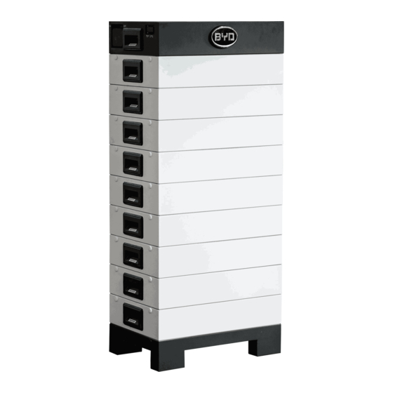
B-Box HV Installation Manual 1 Product Overview B-Box H is the abbreviation of high-voltage battery box, with the operating voltage range within 200~500V. It is applied to the household energy storage field and works together with high-voltage inverter to realize energy storage and release. Each set of battery of the system supports the serial connection of 5~9 battery modules, and parallel connection of 2~5 sets of systems 4 / 35... - Page 5 B-Box HV Installation Manual Position Designation Base B-Plus-H 5 / 35...
-
Page 6: Bcu Introduction
B-Box HV Installation Manual 2 BCU Introduction The battery management and control part, which contains BCU and charge-discharge relay, and connected to the battery modules underneath and to inverter or BMU above. Position Designation Left side terminals Ethernet CAN (Inverter) Grounded Position Designation... - Page 7 B-Box HV Installation Manual Definition of BCU Functional Interfaces Interface Name Description The system positive terminal, connected to the positive terminal of battery interface of inverter. The system negative terminal, connected to the negative terminal of battery interface of inverter. Grounding terminal, connected to the ground.
-
Page 8: Description Of B-Plus-H Interface And Terminal
B-Box HV Installation Manual 3 Description of B-Plus-H Interface and Terminal The battery module provides energy and sends the information about the cell voltage and cell temperature in the battery module to the upper-layer BCU. Pluggable terminal on the battery Side-lock, used to lock the upper and lower batteries. -
Page 9: Box Hv Inverter Configuration List
B-Box HV Installation Manual 4 B-Box HV Inverter Configuration List 4.1 B-Box HV Configuration List with SMA Sunny Boy Storage 1 Phase on Grid Inverter Type B-Plus-H quantity BCU quantity SBS 2.5 5 ~ 9 4.2 B-Box HV Configuration List with Kostal Piko 3 Phase on Grid B-Plus-H quantity BCU quantity... -
Page 10: Preparation
B-Box HV Installation Manual 5 Preparation 5.1 Installation Instructions a) Before installation, ensure that BCU manual switch is switch off. b) The battery shall be installed in a place away from heating source and avoid sparks. The safety distance is greater than 0.5m. c) The connecting cables for installing batteries shall be as short as possible, to prevent excessive voltage drop. -
Page 11: Structure Configuration List
B-Box HV Installation Manual 5.3 Structure Configuration List Type H6.4 H7.7 H9.0 H10.2 H11.5 BCU + base B-Plus-H User manual Installation Manual 5.4 Installation Tools Cross screwdriver Flat tip screwdriver Crimping pliers M3~M10 M3~M6 Adjustable wrench Diagonal cutters Inner hexagon spanner Impact drill 11 / 35... -
Page 12: Personal Protection Equipment
B-Box HV Installation Manual 5.5 Personal Protection Equipment 12 / 35... -
Page 13: Installation Of Single System
B-Box HV Installation Manual 6 Installation of Single System Step 1: open the battery package; Battery Pearl wool Pearl wool Plastic bag Carton 13 / 35... - Page 14 B-Box HV Installation Manual Step 2: Take out the BCU & Base, BCU & Base are locked and packed in the same box (the method is the same as the first step); unlock the lock with inner hexagon spanner, separate the BCU and the base. Tool: Inner hexagon spanner BCU &...
- Page 15 B-Box HV Installation Manual Step 3: adjust the support of the base; drill 4 holes on the wall with M6 expansion bolt (the distance between ground and the bottom holes depends on different module numbers, please refer to picture below; the distance between the bottom two holes and upper two holes is 80mm; the distance between the right two holes and left two holes is 200mm;...
- Page 16 B-Box HV Installation Manual Serial number Bottom hole height(mm) N 786.1 906.1 1026.1 1146.1 1266.1 16 / 35...
- Page 17 B-Box HV Installation Manual Step 4: Install the batteries (5pcs~9pcs), and lock the batteries with the base, ; then install BCU, and lock the batteries with BCU; the installation is completed. Tool: Inner hexagon spanner Stack up the B-Plus-H according to the actual quantity required, and lock the side lock tightly.
- Page 18 B-Box HV Installation Manual Fixing arch Install the Fixing plate BCU fixing Fit in the arch into the BCU, lock fixing plate. the side lock, installation finish. 18 / 35...
-
Page 19: Connecting With The Inverter
B-Box HV Installation Manual 7 Connecting with the Inverter Tools: Cross screwdriver, with torque force: 25± 2.5Nm. Open the top cover of the BCU. Connect the power cable: get the positive and negative cables through the PG head, connect them into BCU case, and then install them onto the positive and negative terminals respectively. - Page 20 B-Box HV Installation Manual Communication cable Ethernet cable 20 / 35...
- Page 21 B-Box HV Installation Manual Cable recommendation: Cable definition Cable diameter Sectional area Recommended (mm) (mm² ) cable type Φ4~Φ6.8 P+ connection cable 6~10 UL1015 10AWG- 8AWG Φ4~Φ6.8 P- connection cable 6~10 UL1015 10AWG- 8AWG Φ4~Φ6.8 Grounding cable 6~10 UL1015 10AWG- 8AWG Φ4~Φ6.8 Communication cable...
-
Page 22: System Boot
1. WIFI First, connect the computer to the system’s WIFI (name: BYD+ product serial number without the first three numbers (for example: product serial number is BYD100171708-00000, then WIFI name will be BYD171708-00000, password: 123456789); then enter the IP: 192.168.5.1 in the browser, and enter the account number and password to log in. - Page 23 B-Box HV Installation Manual 23 / 35...
- Page 24 First set related parameters, mandatory parameters including sever IP (set as bboxhserver.byd.com.cn), installation latitude and longitude, array count (set as 1), number of B-Plus-H (according to actual modules of the system, 5~9pcs), inverter model (e.g SMA, KOSTAL etc.), timezone and tiem, other information is optional.
- Page 25 B-Box HV Installation Manual After clicking on “Apply” button, the system will set the parameters automatically, and please wait patiently, and ensure the system will not be powered off; otherwise, the setting might fail. After setting, the following interface will appear on the webpage: 25 / 35...
- Page 26 B-Box HV Installation Manual Note: After setting, the system will be restarted automatically. Ⅲ. Other functions of the webpage 1) View charging and discharging records Click the ‘Statistic information’ on the left, the user can check the total charging and discharging data, and the charging and discharging history as well. 26 / 35...
- Page 27 B-Box HV Installation Manual 2) View current alarm Click the ‘Current Alarm’ on the left, the user can check the current alarm of the system. 27 / 35...
- Page 28 B-Box HV Installation Manual 3) View history alarm Click the ‘History Alarm’ on the left, the user can check the history alarm. 28 / 35...
- Page 29 B-Box HV Installation Manual 4) View the run data Click the “Run Data” on the left, the user can view the run data of the system, including battery voltage, current and temperature etc. 29 / 35...
- Page 30 B-Box HV Installation Manual 5) Set the password Click the “Set Password” on the left, the user can set the new password. 30 / 35...
- Page 31 B-Box HV Installation Manual 6) Software update Click the ‘Upgrade’ on the left, click ‘Browse’ and upload the updating file, and then click ‘upgrade’ to finish the updating. NOTE: after updating, the system will restart automatically, please wait patiently. 31 / 35...
- Page 32 B-Box HV Installation Manual 7) Reset to default Click the ‘Reboot and Restore’ on the left, select ‘Restore’, and then press ‘Reboot’. NOTE: 1. Be cautious, all configuration settings will be lost after restore; 2. Press ‘Reboot’, system will restart automatically. 3.
- Page 33 B-Box HV Installation Manual 8) View the managing parameters Click the ‘Manage Parameter’ on the left, the user can view the managing parameters, including charge and discharge cut voltage, charge and discharge limit current, temperature and etc. 33 / 35...
- Page 34 B-Box HV Installation Manual 9) View the BMS parameters Click the ‘BMS Parameter’ on the left, the user can view the BMS parameters, including charging protection parameters, discharging protection parameters, temperature and etc. 34 / 35...
-
Page 35: Switch Off The Battery
B-Box HV Installation Manual 8.3 Switch off the system switch of the battery 8.4 Switch on the Inverter, set up the inverter parameter 8.5 Switch on the air switch of the battery, and the system can work normally 9 System Shutdown Note: Please power off the inverter before shutting down the system.
Need help?
Do you have a question about the B-Box H6.4 and is the answer not in the manual?
Questions and answers