BYD Battery-Box Premium Operating Instructions Manual
Hide thumbs
Also See for Battery-Box Premium:
- Operating manual (70 pages) ,
- Quick start manual (17 pages) ,
- Quick start manual (21 pages)
Table of Contents
Advertisement
Quick Links
Advertisement
Table of Contents

Related Manuals for BYD Battery-Box Premium


Summary of Contents for BYD Battery-Box Premium
-
Page 3: Legal Provisions
Legal Provisions Legal Provisions All the information in this document is the property of No part of this document could be reproduced in any way for business use. Internal use is allowed. makes no representations or warranties express or implied, with respect to this document or any of the equipment and/or software it may describe, including (with no limitation) any implied warranties of utility, merchantability, or fitness for any particular purpose. -
Page 4: Table Of Contents
Contents Legal Provisions ............................1 Information on this Document ......................5 1.1. Validity ............................5 1.2. Target Group ..........................5 1.3. Content and Structure of this Document ................5 1.4. Declaration of Conformity ..................... 5 1.5. Levels of Warning Messages ....................5 1.6. - Page 5 5.1.3. Safety Gear ........................18 5.1.4. Additionally Required Installation Material ............18 5.2. Installation..........................19 Electrical Connection ........................21 6.1. Overview of the Connection Area..................21 6.2. Connection Diagram ......................23 6.2.1. One Battery System ....................23 6.2.2. Two Battery Systems....................24 6.2.3. Three Battery Systems....................24 6.3. Connecting the Grounding Conductor................25 6.4.
- Page 6 Decommissioning ..........................41 10. Extension ............................42 11. Troubleshooting ..........................43 11.1. Battery System Behavior under Fault Conditions ............43 11.2. LED Light Designation for Errors ..................43 12. Maintenance and Storage ....................... 45 13. Disposal of the Battery System ...................... 46 14.
-
Page 7: Information On This Document
1 Information on this Document 1. Information on this Document 1.1. Validity This document is valid for the Battery-Box Premium HVS 5.1, 7.7, 10.2, 12.8, and HVM 8.3, 11.0, 13.8, 16.6, 19.3, 22.1 from firmware version BMU 3.16, BMS 3.24. 1.2. Target Group... -
Page 8: Symbols In The Document
Sections performed by qualified person 1.7. Designation in the Document Designation in this document Complete esignation attery ystem BYD Battery-Box Premium HVS&HVM Be Connect Plus Battery Control Unit Battery Information Collector Battery Management System Battery Management Unit State of Charge... -
Page 9: Safety
Section 5.1. The battery system must only be operated in connection with a compatible inverter. The list (BYD Battery-Box Premium HVS & HVM Compatible Inverter List) of these inverters could be found at www.bydbatterybox.com. The battery system is not suitable for supplying life-sustaining medical devices. Please ensure that no personal injury would due to the power outage of the battery system. -
Page 10: Firefighting Measures
2 Safety 2.2.2. Firefighting Measures The battery modules may catch fire when it is put into the fire. In case of a fire, please make sure that an ABC or carbon dioxide extinguisher is nearby. Water cannot be used to extinguish the fire. -
Page 11: Warning Of Electric Shock
2 Safety 2.2.4. Warning of Electric Shock DANGER Danger to life due to electric shock when live components or DC cables are touched The DC cables connected to an inverter may be live. Touching live DC cables results in death or serious injury due to electric shock. Disconnect the battery system and inverter from voltage sources and make sure it cannot be reconnected before working on the device. -
Page 12: Notice Of Property Damage
NOTICE Damage to the battery system due to under voltages If the battery system doesn t start at all, please contact BYD local after-sales service within 48 hours. Otherwise, the battery could be permanently damaged. HVS&HVM Operating Manual... -
Page 13: Scope Of Delivery
3 Scope of Delivery 3. Scope of Delivery BCU and Base Package Battery Module Package Base Battery odule Hanger (BCU part) Documents (Quick Start Guide, Compatible Inverter List, Service Guideline and Checklist ) Hanger (wall part) Screw to fix D on BCU Bolt to fix D and F Screw... -
Page 14: Battery System Overview
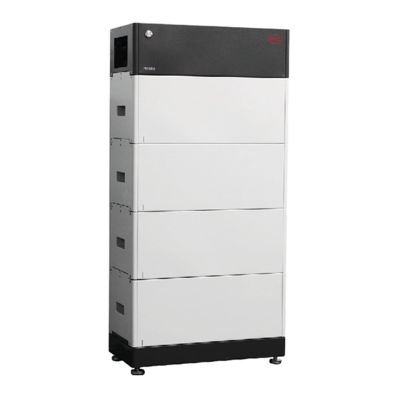
4 Battery System Overview 4. Battery System Overview 4.1. Battery System Description The Battery-Box Premium HVS&HVM is used as a connected battery for the intermediate storage of excess PV energy in an inverter system. Battery odule Base Operating anel LED utton Air witch There are two types of battery modules, HVM and HVS. -
Page 15: Interface
4 Battery System Overview Maximum three battery systems could be connected in parallel. (This restriction does not apply for parallel connection with SMA Sunny Boy Storage 3.7-6.0. Please check the inverter operation manual on how to connect up to three batter The HVS system cannot be connected with the HVM system. -
Page 16: Symbols On The System
Disposal Do not dispose of the system together with household waste lease contact BYD service partner (contact information at the end of this document) to dispose of it in accordance with regulations for electronic waste and used batteries. CE marking The system complies with the requirements of the applicable EU directives. - Page 17 4 Battery System Overview Beware of electrical Beware of danger zone This symbol indicates that the system must be additionally grounded if additional grounding or equipotential bonding is required at the installation site. Keep the battery modules away from children. RCM (Regulatory Compliance Mark), electrical equipment approvals in Australia...
-
Page 18: Led Signals
4 Battery System Overview 4.4. LED Signals white The battery system and blue is initiating. alternatively Idle (the battery system is neither white charging nor discharging). white The battery system slowly is charging. white The battery system quickly is discharging. The battery system is white discharging, and the... -
Page 19: Installation
5 Installation 5. Installation 5.1. Requirements for Installation 5.1.1. Requirements for Installation Location A solid support surface must be available (e.g., concrete or masonry). b) The installation location must be inaccessible to children. The installation location must be suitable for the weight and dimensions of the battery system. -
Page 20: Tools
5 Installation 5.1.2. Tools The tools in the following table could be needed during the installation. 5.1.3. Safety Gear Wear the following safety gear when dealing with the battery system. 5.1.4. Additionally Required Installation Material HVS&HVM Operating Manual... -
Page 21: Installation
5 Installation 5.2. Installation DANGER Danger to life electric shock live DC cables or connectors at the battery system The DC cables connected to the battery system may be live. Touching the DC conductors or the live components lead to lethal electric shocks. Do not touch non-insulated cable ends. - Page 22 5 Installation Install the hanger (BCU part) to the BCU screws (M5x14) using a cylinder screwdriver (8 mm) and tighten them (torque: 5.5 Nm). the BCU on top of the battery modules. ecommend to connect cables on the BCU first when five or more than five battery modules are needed to be installed in one tower.
-
Page 23: Electrical Connection
6 Electrical Connection 6. Electrical Connection 6.1. Overview of the Connection Area Exterior view Gland for Ethernet cable Gland for data cable(s) to connect to an inverter and another battery system Gland for PE Gland for DC+ (P+) Gland for DC- (P-) Interior View HVS&HVM Operating Manual... - Page 24 6 Electrical Connection PE connecting point Panel open sensor switch for CAN protocol switch for RS485 protocol switch for CAN protocol 8 pin terminal blocks for connecting an inverter s data cable.(CAN or RS485 protocol) RJ45 port for connecting an inverter s data cable (CAN protocol) RJ45 port for connecting an inverter s data cable (RS485 protocol) RJ45 port for connecting with other tower(s) (CAN protocol) RJ45 port for Ethernet cable connection...
-
Page 25: Connection Diagram
6 Electrical Connection 6.2. Connection Diagram 6.2.1. One Battery System HVS&HVM Operating Manual... -
Page 26: Two Battery Systems
2.The length of the power cables the combin er box should be same. .If the BYD combiner box is not used the parallel connection device should meet the following requirements. No less than IP55 for the outdoor use. Maximum perating oltage 1000 V DC .The total power cable length between each battery... -
Page 27: Connecting The Grounding Conductor
6 Electrical Connection 6.3. Connecting the Grounding Conductor Additionally required mounting material (not included in the scope of delivery): Conductor SC10-5 b) Grounding cable cross-section: 10 mm² Procedure: the air switch of BCU ake off the perating anel of BCU the plug cable gland c. -
Page 28: The Data Cable Connection To An Inverter
6 Electrical Connection 13. Take the nut on the grounding point off, the PE conductor with a cylinder screwdriver 8 mm (torque, 4 Nm). 6.4. The Data Cable Connection to an Inverter 6.4.1. Connection Options The connection options with different inverters could be read in the Appendix. 6.4.2. -
Page 29: Connecting The Data Cable To Other Battery System(S)
6 Electrical Connection Plug the cable to RJ45 port or to the 8 pin terminal block. the corresponding switch (CAN Inver or RS485 Inver) to the ACT. position (left side, is not applicable for Kostal MP Plenticore). (Choosing CAN Inver or RS485 Inver depends on the protocol that adapted to communicate with the... - Page 30 6 Electrical Connection The connection diagram of two battery systems could be read below. NOTICE Parallel connection is not applicable to SMA Sunny Boy Storage 3.7-6.0. Please check the inverter perating anual on how to connect up to three batter Except for Kostal Piko MP lus The connection diagram of three battery systems could be read below.
- Page 31 6 Electrical Connection Additionally required material (not included in the scope of delivery): One to two data cables Data cable requirements: The length and quality affect the quality of the signal. bserve the following cable requirements. Cable category: Cat5, Cat5e or higher Plug type: etal shielded RJ45 of Cat5, Cat5e or higher Shielding: es...
-
Page 32: Connecting The Network Cables
6 Electrical Connection 6.6. Connecting the Network Cables DANGER Danger to life due to electric shock in case of overvoltages and if surge protection is missing Overvoltages (e. g. in the event of a flash of lightning) can be further conducted into the building and to other connected devices in the same network via the network cables or other data cables if there is no surge protection. -
Page 33: Dc Connection
Y-Bridge connectors are needed to combine these cables. You can refer to Battery-Box Premium HV Combiner Box Basic Technical Requirement, which is available at our website. Please also follow the local, state, provincial, federal, or national laws, regulations, and instructions from the inverter manufacturer to choose the right junction box or Y-Bridge connectors. -
Page 34: Close Up
6 Electrical Connection 6.8. Close up Procedure: Leave a small gap between the BCU and perating anel, so that one hand could hold data cables there. Hold data cables between the BCU and perating anel with one hand, and tighten the nuts on gland a and b with another hand. -
Page 35: Commissioning
7 Commissioning 7. Commissioning 7.1. Switch on the Battery System Requirements: The power cable connection between the battery system and the inverter off. The inverter must be correctly mounted. All cables must be correctly connected. The perating anel is well fixed. 1. -
Page 36: Configure The Battery System
If there is no available, you can 4. After the firmware, the button Check WIFI Settings to connect the battery, which begins with BYD- , and the full name could be found at the BCU label near the ir witch. HVS&HVM Operating Manual... - Page 37 7 Commissioning 6. Choose the inverter brand the battery system 7. Choose the battery system model, HVM or HVS. (HVL is only available for the US market.) And then, set how many battery modules are installed per tower. Check the summary of the configuration information tick the sentence, and Restart the Be Connect if it...
-
Page 38: Switch On And Commission The Inverter
7 Commissioning 7.3. Switch on and Commission the Inverter 7.3.1. On rid Application Procedure: 1. Mount and connect the inverter according to the inverter manufacturer`s instruction. 2. Switch on the nverter. onfigure the inverter according to the inverter manufacturer instruction. If the battery information could be read correctly , it means the connection is all right. -
Page 39: Off Grid Applications
7 Commissioning 7.3.2. Off rid Applications Procedure: 1. Mount and connect the inverter according to the inverter manufacturer s instruction. 2. Switch on the inverter. 3. Black tart: ress the LED Button for 3 seconds on the BCU of the master System. onfigure the inverter according to the inverter manufacturer s instruction. -
Page 40: Switch On The Battery System
(if available) -
Page 41: Operation
8 Operation HVS&HVM Operating Manual... -
Page 42: Safety Design
8 Operation 8.3. Safety Design The battery system cannot be turned on when the perating anel is removed. The system will switch off automatically if there is no communication with an inverter for 30 minutes or there is an error for 10 minutes. 8.4. -
Page 43: Decommissioning
9 Decommissioning 9. Decommissioning DANGER Danger to life electric shock live DC cables or conductors at the battery system The DC cables connected to the battery system may be live. Touching the DC conductors or the live components lead to lethal electric shocks. Do not touch non-insulated cable ends. -
Page 44: Extension
10 Extension 10. Extension The SOC of the existing system and the module should be similar before module the existing system. Procedure: Voltage HVS&HVM Operating Manual... -
Page 45: Troubleshooting
NOTICE Damage to the battery system due to under voltages If the battery system doesn t start at all, please contact BYD local after-sales service within 48 hours. Otherwise, the battery could be permanently damaged. 11.2. LED Light Designation for Errors... - Page 46 11 Troubleshooting Blue LED is twelve times Inverter communication failure Blue LED is thirteen times Address registration failed Blue LED is fourteen times System initiating failed HVS&HVM Operating Manual...
-
Page 47: Maintenance And Storage
12 Maintenance and Maintenance and Storage Cleaning It is recommended that the battery system be cleaned periodically. If the enclosure is dirty, please use a soft, dry brush or a dust collector to remove the dust. Liquids such as solvents, abrasives, or corrosive liquids should not be used to clean the enclosure. -
Page 48: Disposal Of The Battery System
13 Disposal of the Battery System Disposal of the Battery System Disposal of the system must comply with the local applicable disposal regulations for electronic waste and used batteries. battery system with your household waste. Avoid exposing the batteries to high humidity or corrosive atmospheres. HVS&HVM Operating Manual... -
Page 49: Technical Data
14 Technical Data 14. Technical Data HVS&HVM Operating Manual... - Page 50 14 Technical Data HVS&HVM Operating Manual...
-
Page 51: Contact Information
15 Contact Information 15. Contact Information Note: Please also see the Battery-Box Premium HVS/HVM Service Guideline and Checklist for troubleshooting. The latest version is available at our website www.bydbatterybox.com. HVS&HVM Operating Manual... -
Page 52: Appendix Connection Options With Inverters
Appendix Connection Options with Inverters Appendix Connection Options with Inverters lease first check if the planned configuration is already released according to the latest Battery-Box Premium HVS/HVM Compatible Inverter List. NOTICE Parallel connection is not applicable to SMA Sunny Boy Storage 3.7-6.0. Please... - Page 53 Appendix Connection Options with Inverters SMA ST 5.0-10.0 SE Option a SMA ST 5.0-10.0 HVS&HVM Operating Manual...
- Page 54 Appendix Connection Options with Inverters HVS&HVM Operating Manual...
- Page 55 Appendix Connection Options with Inverters Kostal P HVS&HVM Operating Manual...
- Page 56 Appendix Connection Options with Inverters Kaco blueplanet hybrid 6.0-10.0 TL3 GRID Terminal-1 Terminal-2 Terminal-3 LO AD Terminal-4 Terminal-1 Terminal-2 Terminal-3 Terminal-4 HVS&HVM Operating Manual...
- Page 57 Appendix Connection Options with Inverters GRID Terminal-1 Terminal-2 Terminal-3 LO AD Terminal-4 HVS&HVM Operating Manual...
- Page 58 Appendix Connection Options with Inverters HVS&HVM Operating Manual...
- Page 59 Appendix Connection Options with Inverters HVS&HVM Operating Manual...
- Page 60 Appendix Connection Options with Inverters HVS&HVM Operating Manual...
- Page 61 Appendix Connection Options with Inverters HVS&HVM Operating Manual...
- Page 62 Appendix Connection Options with Inverters HVS&HVM Operating Manual...
- Page 63 Appendix Connection Options with Inverters HVS&HVM Operating Manual...
- Page 64 Appendix Connection Options with Inverters Deye HVS&HVM Operating Manual...
- Page 65 Appendix Connection Options with Inverters HVS&HVM Operating Manual...
- Page 66 Appendix Connection Options with Inverters GRID Terminal-1 Terminal-2 Terminal-3 LO AD Terminal-4 Terminal-1 Terminal-2 Terminal-3 Terminal-4 HVS&HVM Operating Manual...
- Page 67 Appendix Connection Options with Inverters GRID Terminal-1 Terminal-2 Terminal-3 LO AD Terminal-4 HVS&HVM Operating Manual...
- Page 68 Appendix Connection Options with Inverters HVS&HVM Operating Manual...
- Page 69 Appendix Connection Options with Inverters HVS&HVM Operating Manual...
- Page 70 Appendix Connection Options with Inverters Canadian Solar GoodWe/ Viessmann/ Canadian Solar HVS&HVM Operating Manual...
- Page 71 Appendix Connection Options with Inverters Canadian Solar GoodWe/ Viessmann/ Canadian Solar HVS&HVM Operating Manual...
Need help?
Do you have a question about the Battery-Box Premium and is the answer not in the manual?
Questions and answers
What happens after power outage
The BYD Battery-Box Premium is not suitable for supplying life-sustaining medical devices. Users must ensure that no personal injury occurs due to a power outage. If the battery system does not start at all after a power outage, the user must contact BYD customer service or an authorized service partner within 48 hours. Failure to do so may result in permanent battery damage.
This answer is automatically generated