
Related Manuals for BYD HV Series


Summary of Contents for BYD HV Series
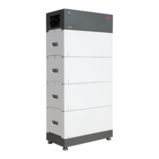
- Page 2 HV SERIES 3 x HVS 12.8 10.2 12.8 38.4Kwh Ø Min. 2 x module, Max. 5 x modules per tower Ø Max. 38.4kWh (15 modules) in parallel...
- Page 3 HV SERIES 3 x HVM 22.1 66.2Kwh 11.0 13.8 16.6 19.3 22.1 Ø Min. 3 x module, Max. 8 x modules per tower Ø Max. 66.2kWh (24 modules) in parallel...
- Page 4 LV SERIES LV Flex Lite 12.0 16.0 16 x LVS 16.0 20.0 24.0 Ø Max. 4 modules per tower when parallel; Ø Max. 256kWh (64 modules) in parallel Ø Min. 1 x module, Max. 6 x modules per tower...
- Page 5 LV SERIES LV Flex Lite Ø Max. 983kWh (64 modules) in parallel 2 x LVL 64 x LVL 15.4 15.4 15.4 983Kwh...
- Page 6 LV SERIES LV Flex Lite LV Flex Lite LV Flex Lite LV Flex Lite LV Flex Lite Ø Max. 320kWh (64 modules) in parallel 10.0 15.0 20.0...
- Page 7 LV SERIES 2 x LVL 64 x LVL 15.4 15.4 15.4 BMU - LVL/LVS/LV Flex Lite 16 x LVS 16.0 12.0 16.0 20.0 24.0 LV Flex Lite LV Flex Lite LV Flex Lite LV Flex Lite 64 x LV FLEX LITE 5.0 10.0 15.0 20.0...
- Page 8 FD-LV.5.0 Is Coming...
- Page 9 FD-LV5.0...
- Page 10 FD-LV5.0 Affordable Compact Flexibile...
- Page 11 FD-LV5.0...
- Page 12 FD-LV5.0 Floor Installation Space-Saving...
- Page 13 FD-LV5.0 Connection Extension...
- Page 14 FD-LV5.0 Configurate Automatically LED Signal Code...
- Page 15 FD-LV5.0 Switch Off Switch On Inverter Switch Battery Battery Inverter Switch...
- Page 16 FD-LV 5.0 More FD Series will be availble soon More inverters are under test...
- Page 18 BYD+FD SERIES (204-512V) HVS 5.1 10.2 HVS 12.8 x HVS 12.8 = 38.4kWh IP55 Outdoors (153-409V) HVM 8.3 11.0 13.8 16.6 19.3 HVM 22.1 x HVM 22.1 = 66.2kWh (51.2V) LVS 4.0 12.0 16.0 20.0 LVS 24.0 16 x LVS 16.0 = 256kWh (51.2V)
- Page 19 Q&A...
- Page 20 Installation Guideline...
- Page 21 HVS/M: Installation Documents Minimum Configuration List https://www.bydbatterybox.com/...
- Page 22 HVS/M: Scope of Delivery...
- Page 23 HVS/M: Non- Scope of Delivery...
- Page 24 HVS/M: Tools Needed...
- Page 25 HVS/M: Installation Environment...
- Page 26 HVS/M...
- Page 27 HVS/M Installation...
- Page 28 HVS/M...
- Page 29 HVS/M...
- Page 30 HVS/M: Grounding...
- Page 31 HVS/M: Data Cable to Inverter...
- Page 32 HVS/M: Data Cable to Inverter RJ45 8 Pin Connector...
- Page 33 HVS/M Data Cable Between Battery:Two Towers...
- Page 34 HVS/M Data Cable Between Battery: Three Towers...
- Page 35 HVS/M: Data Cable to Network...
- Page 36 HVS/M: DC Cable Connection...
- Page 37 HVS/M: Single Tower Diagram...
- Page 38 HVS/M: Two Towers Diagram...
- Page 39 HVS/M: Three Towers Diagram...
- Page 40 HVS/M: WLAN Restart Press the LED button for three times (each time around one second) within six seconds could reset the BCU WLAN.
- Page 41 HVS/M Switch on Procedure: On Grid...
- Page 42 HVS/M Switch on Procedure: Off Grid Black Start: Press all LED Buttons for 3 seconds on the BCU starting from Master Master Slave 1 Slave 2...
- Page 43 HVS/M: Switch off Procedure...
- Page 44 HVS/M: Be Connect Configuration Assure the newest firmware When download firmware, please connect your home wifi or cellphone data; when upload or configurate please connect the BCU wifi.
- Page 45 HVS/M: Extension Reconfiguration after Extension...
- Page 46 HVS/M: Installation Video...
- Page 47 HVS/M: Installation Cases...
- Page 48 LVS: Installation Documents Minimum Configuration List https://www.bydbatterybox.com/...
- Page 49 LVS: Scope of Delivery...
- Page 50 LVS: Non- Scope of Delivery...
- Page 51 LVS: Tools Needed...
- Page 52 LVS: Installation Environment...
- Page 54 LVS Installation...
- Page 55 LVS: Grounding...
- Page 56 LVS: Data Cable Connection...
- Page 57 LVS: DC Cable Connection...
- Page 58 LVS: Switch on Procedure...
- Page 59 LVS: Switch off Procedure...
- Page 60 LVS: Single Tower Diagram...
- Page 61 LVS: Multi-tower Diagram Address 2 Address 3 Address 1...
- Page 62 LVS: Be Connect Configuration Assure the newest firmware When download firmware, please connect your home wifi or cellphone data; when upload or configurate please connect the BMU wifi.
- Page 63 LVS: Extension Reconfiguration after Extension...
- Page 64 LVS: Installation Video...
- Page 65 LVS: Installation Cases...
- Page 66 LVL: Installation Documents Minimum Configuration List https://www.bydbatterybox.com/...
- Page 67 LVL: Scope of Delivery...
- Page 68 LVL: Non- Scope of Delivery...
- Page 69 LVL: Tools Needed...
- Page 70 LVL: Installation Environment...
- Page 72 LVL: Single...
- Page 73 LVL: One Stack...
- Page 74 LVL: Cable Connection...
- Page 75 LVL: Single Battery Diagram...
- Page 76 LVL: Multi-Stack Diagram...
- Page 77 LVL: Switch on Procedure...
- Page 78 LVL: Switch off Procedure...
- Page 79 LVL: Be Connect Configuration Assure the newest firmware When download firmware, please connect your home wifi or cellphone data; when upload or configurate please connect the BMU wifi.
- Page 80 LVL: Installation Video...
- Page 81 LVL: Installation Cases...
- Page 82 LVL: Installation Cases 64 LVL ü Battery: 64 LVL—983kwh ü Application: 3 Phase Backup ü Inverter: 12 Victron Quattro 15000 ü Country: South Africa...
- Page 83 LVL: Installation Cases ü Battery: 26 LVL—400kwh ü Application: 3 Phase Backup ü Inverter: 12 Victron Quattro 15000 ü SA National Lottery...
- Page 84 LV Flex Lite: Installtion Documents Minimum Configuration List https://www.bydbatterybox.com/ Quick Start Guide Operating Manual...
- Page 85 LV Flex Lite: Scope of Delivery...
- Page 86 LV Flex Lite: Non- Scope of Delivery...
- Page 87 LV Flex Lite: Tools Needed...
- Page 88 LV Flex Lite (Without Cabinet)
- Page 89 LV Flex Lite: Installation Environment...
- Page 90 LV Flex Lite (Without Cabinet): DC Connection • Lead the terminals of the DC cable there. • Seal the cover with plastic rivets. • Open the cover of the DC connection port. • Tighten the bolts. (torque, 6±1N·m) • Get the bolts out. •...
- Page 91 LV Flex Lite (Without Cabinet): Data Cable Connection INVERTER ETHERNET...
- Page 92 LV Flex Lite (Without Cabinet): Connection Diagram...
- Page 93 LV Flex Lite (Without Cabinet): Switch on Procedure...
- Page 94 LV Flex Lite (Without Cabinet): Switch off Procedure...
- Page 95 LV Flex Lite (With Cabinet): Pre-wired...
- Page 96 LV Flex Lite (With Cabinet): Connection Diagram...
- Page 97 LV Flex Lite (With Cabinet):Connection Diagram...
- Page 98 LV Flex Lite (With Cabinet): Grounding...
- Page 99 LV Flex Lite (With Cabinet): DC Cable...
- Page 100 LV Flex Lite (With Cabinet): Data Cable...
- Page 101 LV Flex Lite (With Cabinet): Busbar...
- Page 102 LV Flex Lite (With Cabinet): Switch on Procedure...
- Page 103 LV Flex Lite (With Cabinet): Switch off Procedure...
- Page 104 LV Flex Lite: Be Connect Configuration When download firmware, please connect your home wifi or cellphone data; when upload or configurate Assure the newest firmware please connect the BMU wifi.
- Page 105 LV Flex Lite: Be Connect Configuration When download firmware, please connect your home wifi or cellphone data; when upload or configurate Assure the newest firmware please connect the BMU wifi.
- Page 106 LV Flex Lite: Extension How to Extend Capacity? 1. Switch off the system; 2. Add the new battery and connect the cables; 3. Switch on the battery system; 4. Reconfigurate the new battey system via Be Connect 5. Restart...
- Page 107 LV Flex Lite: Installation Cases...
-
Page 108: Social Media
Social Media https://www.linkedin.com/company/byd-battery-box https://twitter.com/BYD_BatteryBox https://www.facebook.com/BatteryBoxBYD Installation Video: https://www.youtube.com/watch?v=sLJKRbH3f90...
Need help?
Do you have a question about the HV Series and is the answer not in the manual?
Questions and answers