
Related Manuals for BYD Battery-Box Premium Series


Summary of Contents for BYD Battery-Box Premium Series
- Page 1 Battery-Box Premium Operating Manual HVS 5.1, 7.7, 10.2, 12.8 HVM 8.3, 11.0,13.8, 16.6, 19.3, 22.1 A High Voltage Battery System BYD Europe B.V. V1.0...
-
Page 2: Legal Provisions
Legal Provisions All the information in this document is the property of BYD Europe B.V. No part of this document could be reproduced in any way for business use. Internal use is allowed. BYD Europe B.V. makes no representations or warranties express or implied, with respect to this document or any of the equipment and/or software it may describe, including (with no limitation) any implied warranties of utility, merchantability, or fitness for any particular purpose. -
Page 3: Table Of Contents
Content Legal Provisions ..........................2 Information on this Document ....................5 1.1. Validity ..........................5 1.2. Target Group ........................5 1.3. Content and Structure of this Document ................5 1.4. Declaration of Conformity ....................5 1.5. Levels of Warning Messages ................... 5 1.6. - Page 4 Electrical Connection ....................... 20 6.1. Overview of the Connection Area ................... 20 6.2. Connection Diagram ...................... 22 6.2.1. One Battery System ....................22 6.2.2. Multiple Battery Systems .................... 23 6.3. Connecting the Grounding Conductor ................23 6.4. The Data Cable Connection to Inverter ................25 6.4.1.
-
Page 5: Information On This Document
1. Information on this Document 1.1. Validity This document is valid for the Battery-Box Premium HVS 5.1, 7.7, 10.2, 12.8, and HVM 8.3, 11.0, 13.8, 16.6, 19.3, 22.1. 1.2. Target Group The instructions in this document may only be performed by qualified persons who must have the following skills: •... -
Page 6: Symbols In The Document
Sections describing activities to be performed by qualified persons only. 1.7. Designation in the Document Designation in this document Complete designation battery system Battery-Box Premium HVS&HVM Battery Control Unit Battery Information Collector Battery Management System Battery Management Unit BYD Europe B.V. State of Charge... -
Page 7: Safety
The battery system is suitable for indoor and outdoor use under the conditions mentioned in Section 5.1. The battery system must only be operated in connection with a compatible inverter. The list (BYD Battery-Box Premium HVS & HVM Compatible Inverter List) of these inverters could be found at www.bydbatterybox.com. -
Page 8: Battery Modules Handling And Storage Guide
2.2.3. Battery Modules Handling and Storage Guide • The battery modules and its components should be protected from damage when transporting and handling. • Do not impact, pull, drag, or step on the battery modules. • Do not insert unrelated objects into any part of the battery modules. •... -
Page 9: Warning Of Overvoltages
Only open the BCU if the humidity is within the thresholds and the environment is free of • sand and dust. NOTICE Damage to the battery system due to under voltages If the battery system doesn't start at all, please contact BYD local after-sales service • within 48 hours. Otherwise, the battery could be permanently damaged. -
Page 10: Scope Of Delivery
3. Scope of Delivery M6X16 M4X14 M5X14 Battery module Hanger (BCU part) Base Documents (Quick Start Guide, Compatible Inverter List, Packing List) Hanger (wall part) Screw to fix the hanger on BCU Bolt to fix the BCU part and wall part hangers Foot Screw to fix the connection between modules, base, and BCU.(two pcs in the BCU package, and two pcs in each battery module package) -
Page 11: Battery System Overview
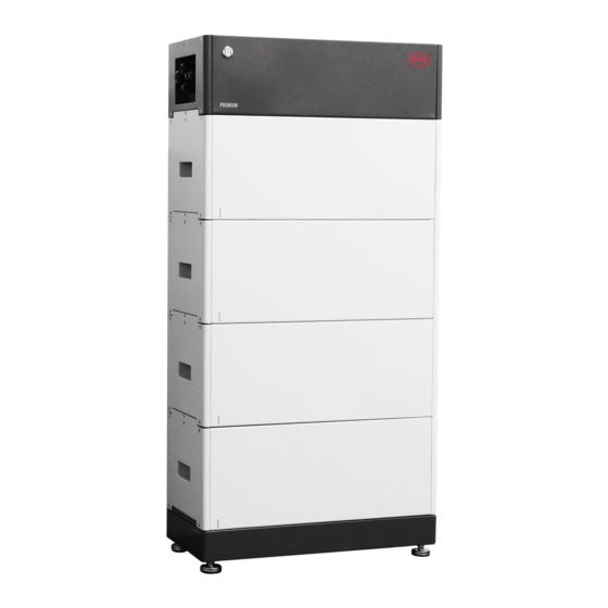
4. Battery System Overview 4.1. Battery System Description The Battery-Box Premium HVS&HVM is used as a connected battery for the intermediate storage of excess PV energy in an inverter system. Battery module Base Operating Panel Button with LED Air switch There are two types of battery modules, HVM and HVS. -
Page 12: Interface
Internet, it will join our Be Connect Monitoring. Be Connect Monitoring is a platform for BYD to provide remote service to customers. It can diagnose your battery system, and update the firmware. It is highly recommended you to connect the battery system to the Internet to have a better service. - Page 13 Keep the battery modules away from open flame or ignition sources. Beware of electrical voltage. Beware of a danger zone This symbol indicates that the system must be additionally grounded if additional grounding or equipotential bonding is required at the installation site.
-
Page 14: Led Signals
4.4. LED Signals Flashing white and The battery system blue alternatively is initiating. Idle (the battery system is neither Glowing white charging nor discharging). The battery system Flashing white slowly is charging. The battery system Flashing white quickly is discharging. The battery system Flashing white and is discharging, and... -
Page 15: Installation
5. Installation 5.1. Requirements for Installation 5.1.1. Requirements for Installation Location a) A solid support surface must be available (e.g., concrete or masonry). b) The installation location must be inaccessible to children. The installation location must be suitable for the weight and dimensions of the battery system. d) The installation location must not be exposed to direct solar irradiation. -
Page 16: Tools
Recommended Clearances: 5.1.2. Tools The tools in the following table could be needed during the installation. Pencil Flat-head screwdriver Scissor Phillips screwdriver bit Torque wrench Crimping plier Wire stripper Wrench Tape measure Drill Cylinder screwdriver bit Hair dryer... -
Page 17: Safety Gear
5.1.3. Safety Gear Wear the following safety gear when dealing with the battery system. Insulated gloves Safety goggles Safety shoes 5.1.4. Additionally Required Installation Material Metal shield RJ45 plug, 10mm Heat shrink tubing M8x40 SC10-5 DC power cable cat5 shield 5.2. - Page 18 Additionally required installation material (not included in the scope of delivery): Two screws suitable for the support surface (diameter: 8 mm) • Where necessary, two screw anchors suitable for the support surface and the screws. • Procedure: Take the base from the package out, and install the four feet with a wrench.
- Page 19 Hold the hanger (wall part) where it intends to be mounted on the wall and mark the position of the drill holes. Please pay attention that there may be power cables or other supply lines (e.g., gas or water) routed in the wall. Ensure that no lines are laid in the wall, which could be damaged when drilling holes.
-
Page 20: Electrical Connection
6. Electrical Connection 6.1. Overview of the Connection Area Exterior view Gland for Ethernet cable Gland for inverter and another battery system data cable Gland for PE Gland for DC+ (P+) Gland for DC- (P-) Interior View ACT. R 120Ω DEA. - Page 21 PE connecting point Panel open sensor Terminal resistor for the CAN protocol circuit with inverter Terminal resistor for the RS485 protocol circuit with inverter Terminal resistor for the CAN protocol circuit with other systems (s) 8 pin terminal blocks for connecting an inverter`s data cable. (CAN or RS485 protocol) RJ 45 port for connecting an inverter`s data cable.
-
Page 22: Connection Diagram
6.2. Connection Diagram 6.2.1. One Battery System INVERTER... -
Page 23: Multiple Battery Systems
6.2.2. Multiple Battery Systems INVERTER BATT COM L=length L1=L2=L3(red) L4=L5=L6(black) Master Slave1 Slave2 6.3. Connecting the Grounding Conductor Additionally required mounting material (not included in the scope of delivery): a) Conductor SC10-5 b) Grounding cable cross-section: 10 mm² Procedure: Make sure the air switch of BCU is off. Take off the Operating Panel of BCU, with a Phillips screwdriver PD2. - Page 24 Take out the plug on cable gland c. Take off the nut of the cable gland. Take off the cable support sleeve inside of the cable gland. Get the PE inside of the cable support sleeve. Lead the PE through cable gland c. Strip the grounding cable and make the length(L on the right drawing)stripped 2-3 mm longer than the tube of the conductor (E on the right drawing).
-
Page 25: The Data Cable Connection To Inverter
6.4. The Data Cable Connection to Inverter 6.4.1. Connection Options The connection options with different inverters could be read in the Appendix. 6.4.2. Connecting the Data Cable of the Inverter Additionally required mounting material (not included in the scope of delivery): One data cable Data cable requirements: The cable length and quality affect the quality of the signal. -
Page 26: Connecting The Data Cable For Other Battery System(S)
The method to plug the data cable into the 8 pin terminal block: 1. Strip the communication cable 50 mm. 2. Trim the cable shield to a length of 10 mm 6 mm and fold it over the cable sheath. 3. - Page 27 The connection diagram of three battery systems could be read below. Cat5 Cat5 Master Slave1 Slave2 Additionally required material (not included in the scope of delivery): • One to two data cables Data cable requirements: The cable length and quality affect the quality of the signal. Observe the following cable requirements.
-
Page 28: Connecting The Network Cables
WELL COVERED BY THE PLUG BEFORE FINISHING THE INSTALLATION. OTHERWISE, THE WATER HAS THE POSSIBILITY TO GET INSIDE OF BCU. Lead the data cable through cable gland b. Plug the cable to the corresponding RJ45 port. Swipe the terminal resistor (Parallel) according to the drawing. 6.6. -
Page 29: Dc Connection
Lead the network cable through cable gland a. Plug the cable to the corresponding RJ45 port. 6.7. DC Connection DANGER Danger to life from electric shock due to live DC cables or conductors at the battery system The DC cables connected to the battery system may be live. Touching the DC conductors or the live components leads to lethal electric shocks. -
Page 30: Close Up
6.8. Close up Procedure: Leave a small gap between the BCU and Operating Panel, so that one hand could hold data cables there. Hold data cables between the BCU and Operating Panel with one hand, and tighten the nuts on grand a and b with another hand. -
Page 31: Commissioning
7. Commissioning 7.1. Commission the Battery System Requirements: The power cable connection between the battery system and the inverter is switched off. • The inverter must be correctly mounted. • All cables must be correctly connected. • The Operating Panel is well fixed. •... - Page 32 4. Read the privacy policy and click the Confirm button to go to the next page. You can also download the full PDF document by Privacy Policy of clicking the Download button, which requires the Internet SHEN ZHEN BYD available on your device. ELECTRONIC CO,.LTD Responsible for data processing (controllers): Confirm...
- Page 33 Tower:xx Grid: xxxxxx There will be a prompt “Succeeded” when the configuration is Phase:xxxxxx completed. The system(s) has been configured according yo BYD Battery-Box Premium Compatible Inverter List or Minimum Configurea List Restart the Be Connect if it was stuck somewhere. Submit...
-
Page 34: Switch Off The Battery System
7.3. Switch off the Battery System Press the Button with LED for 5 seconds. Then the battery system will be switched off. If there are two or three battery systems are connected in parallel, only the Button on the master system needs to turn off. -
Page 35: Decommissioning
8. Decommissioning DANGER Danger to life from electric shock due to live DC cables or conductors at the battery system The DC cables connected to the battery system may be live. Touching the DC conductors or the live components leads to lethal electric shocks. •... -
Page 36: Extension
9. Extension The battery system could be extended at any time. The SOC of the existing system and the module to be added should be similar before the module adding on the existing system. Procedure: Get the SOC figure of the new battery module. Normally, the SOC of a new battery module before shipment is between 30~40%. -
Page 37: Troubleshooting
Troubleshooting 10.1. Overview The customer is not supposed to replace or change the parts. If the white LED flashes once for one second and then blue LED flashes several times (every time one second), that means an error happens. The times of blue LED flashes are the error codes. Contact our local after-sales service within 48 hours when you observe an error. -
Page 38: Maintenance And Storage
Maintenance and Storage Cleaning It is recommended that the battery system be cleaned periodically. If the enclosure is dirty, please use a soft, dry brush or a dust collector to remove the dust. Liquids such as solvents, abrasives, or corrosive liquids should not be used to clean the enclosure. Maintenance The battery module should be stored in an environment with a temperature range between -10°C~... -
Page 39: Disposal Of The Battery System
• Do not dispose of the battery system with your household waste. • Avoid exposing the batteries to high temperatures or direct sunlight. • Avoid exposing the batteries to high humidity or corrosive atmospheres. • For more information, please contact BYD. -
Page 40: Technical Data
Technical Data HVS 5.1 HVS 7.7 HVS 10.2 HVS 12.8 Battery Module HVS (2.56 kWh, 102.4 V, 38 kg) Number of Modules Usable Energy [1] 5.12 kWh 7.68 kWh 10.24 kWh 12.8 kWh Max Output Current [2] 25 A 25 A 25 A 25 A Peak Output Current [2]... - Page 41 [1] DC Usable Energy, Test conditions: 100% DOD, 0.2C charge & discharge at +25° C. System Usable Energy may vary with different inverter brands. [2] Charge derating will occur between -10° C and +5° C. [3] Refer to BYD Battery-Box Premium Limited Warranty.
-
Page 42: Contact Information
Contact Information BYD Global Service bboxservice@byd.com Social media link Telephone: +86 755 89888888-47175 https://www.facebook.com/BatteryBoxBYD/ Address:No.3009,BYD Road, https://twitter.com/BYD_BatteryBox Pingshan,Shenzhen,518118,P.R.China https://www.linkedin.com/company/byd-battery-box www.bydbatterybox.com Australia Alps Power Pty Ltd Europe EFT-Systems GmbH service @alpspower.com.au service@eft-systems.de Telephone: +61 2 8005 6688 Telephone +49 9352 8523999... -
Page 43: Appendix Connection Options With Inverters
Appendix Connection Options with Inverters 1 2 3 4 5 6 7 8 6 mm... - Page 44 1 2 3 4 5 6 7 8 6 mm...
- Page 45 1 2 3 4 5 6 7 8 KOSTAL KOSTAL 6 mm...
- Page 46 GoodWe 1 2 3 4 5 6 7 8 GoodWe GoodWe GoodWe GoodWe 6 mm...
- Page 47 1 2 3 4 5 6 7 8 UNGROW SUNGROW 6 mm...
- Page 48 1 2 3 4 5 6 7 8 6 mm...
- Page 49 1 2 3 4 5 6 7 8 Fronius Fronius 6 mm...
Need help?
Do you have a question about the Battery-Box Premium Series and is the answer not in the manual?
Questions and answers