
Related Manuals for BYD HVL 12.0


Summary of Contents for BYD HVL 12.0
- Page 1 Battery-Box Premium Operating Manual HVL 12.0, 16.0, 20.0, 24.0, 28.0, 32.0 A High-Voltage Battery System BYD AMERICA LLC V1.3 Be Connect 2.0...
-
Page 2: Legal Provisions
Legal Provisions All the information in this document is the intellectual property of BYD and it contains BYD’s proprietary trade secrets - infringement, misappropriation or misuse is strictly forbidden. No part of this document could be copied or reproduced in any way for use by another competing business. -
Page 3: Table Of Contents
Content Legal Provisions..............................1 Information on this Document........................5 1.1. Validity.............................. 5 1.2. Target Group........................... 5 1.3. Content and Structure of this Document.................. 5 1.4. Declaration of Conformity......................5 1.5. Levels of Warning Messages......................5 1.6. Symbols in the Document......................6 1.7. - Page 4 5.1.4. Safety Gear.........................18 5.1.5. Additionally Required Installation Materials............... 18 5.2. Installation............................. 19 Electrical Connection..........................22 6.1. Overview of the Connection Area..................... 22 6.2. Connection Diagram........................24 6.2.1. One Battery System......................24 6.2.2. Two Battey System......................25 6.2.3. Three Battey System......................25 6.3. PE and DC Cables Connection....................26 6.4.
- Page 5 Maintenance and Storage......................43 Disposal of the Battery System..................... 44 Technical Data...........................45 Contact Information........................46 Appendix Connection Options with Inverters....................47...
-
Page 6: Information On This Document
1. Information on this Document 1.1. Validity This document is valid for the Battery-Box Premium HVL 12.0, 16.0, 20.0, 24.0, 28.0 and 32.0 from firmware version BMU 3.16 and BMS 3.24. 1.2. Target Group The instructions in this document may only be performed by a qualified person who must have the following skills: •... -
Page 7: Symbols In The Document
1.7. Designation in the Document Designation in this Document Complete Designation Battery system Battery-Box Premium HVL Battery Control Unit Battery Information Collector Battery Management System Battery Management Unit BYD America LLC State of Charge... -
Page 8: Safety
Alterations to the battery system, e.g., changes or modifications are not allowed unless the written permission of BYD is granted. Unauthorized alterations will void the guarantee and warranty claims. BYD shall not be held liable for any damage caused by such changes. The type label should always be attached to the battery system. -
Page 9: Firefighting Measures
2.2.2. Firefighting Measures The battery modules may catch fire when it is put into the fire. In case of a fire, please make sure that an ABC or carbon dioxide extinguisher is nearby. Water cannot be used to extinguish the fire. Full protective clothing and self-contained breathing apparatus are required for the firefighters to extinguish the fire. -
Page 10: Warning Of Electric Shock
2.2.4. Warning of Electric Shock DANGER Danger to life due to electric shock when live components or DC cables are touched The DC cables connected to an inverter may be live. Touching live DC cables results in death or serious injury due to electric shock. •... -
Page 11: Notice Of Property Damage
• sand and dust. NOTICE Damage to the battery system due to under voltages If the battery system doesn't start at all, please contact BYD's local after-sales service team • within 48 hours. Otherwise, the battery could be permanently damaged. -
Page 12: Scope Of Delivery
3. Scope of Delivery BCU and Base Package Battery Module Package Base Battery Module Hanger (BCU Part Left) Hanger (BCU Part Right) Documents (Quick Start Guide, Compatible Inverter List, Packing List) Hanger (wall part) M5 screw to fix D/E on BCU M6 bolt and nut to fix D and G M4 x 14 countersunk screw for fixing the modules, base and BCU together... -
Page 13: Battery System Overview
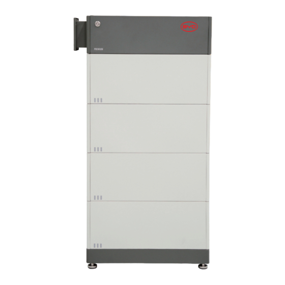
4. Battery System Overview 4.1. Battery System Description The Battery-Box Premium HVL is used as a connected battery for the intermediate storage of excess PV energy in an inverter system. Battery module Base Operating panel LED button Air switch There are three stripes printed on the module. -
Page 14: Interface
The battery system is equipped with an "Ethernet" port as a standard. When your battery accesses the internet, it will join the Be Connect Monitoring, which is a platform that BYD's service team could diagnose the battery system and update firmware remotely for customers. -
Page 15: Symbols On The System
Disposal Do not dispose of the system together with household waste. Please contact BYD's Service (contact information at the end of this document) to dispose of it in accordance with regulations for electronic waste and used batteries. FCC marking The system complies with the requirements of the applicable FCC Rules. -
Page 16: Led Signals
North America Listed Mark from SGS. Do not short-circuit. 4.4. LED Signals Blinking white and blue White 0.5s The battery system is 0.5s alternatively initiating. Blue Idle (the battery White system is neither Solid white charging nor Blue discharging). White The battery system is Blinking white slowly charging. -
Page 17: Installation
5. Installation 5.1. Requirements for Installation 5.1.1. Requirements for Installation Location A solid support surface must be available (e.g., concrete or masonry). b) The installation location must be inaccessible to children. The installation location must be suitable for the weight and dimensions of the battery system. -
Page 18: Requirements For Installation Space
5.1.2. Requirements for Installation Space For multiple towers installation, a minimum of 305 mm (12 in.) should be reserved between per battery tower or openings (e.g. windows, doors, HVAC inlets or other operable openings), and a minimum of 508 mm (20 in.) should be reserved in the front of the battery towers. Other clearances, please refer to following figure. -
Page 19: Tools
5.1.3. Tools The tools in the following table could be needed during the installation. Network Wire Clamp Phillips Screwdriver Bit Flat-Head Screwdriver Torque Wrench Wire Stripper Crimping Plier Wrench Tape Measure Drill Hair dryer Cylinder Screwdriver 5.1.4. Safety Gear Wear the following safety gear when dealing with the battery system. Insulated gloves Safety goggles Safety shoes... -
Page 20: Installation
5.2. Installation DANGER Danger to life due to electric shock resulting from live DC cables or connectors at the battery system The DC cables connected to the battery system may be live. Touching the DC conductors or the live components leads to lethal electric shocks. •... - Page 21 4. Put the installed base and feet along the wall , and keep a distance of 12~19 mm (15/32 to 3/4 in) between the wall and the base. 5. Take a battery module out of the package and mount it on the base. Pay attention to the direction of the module.
- Page 22 10. Hold the hanger (wall part) where it intends to be mounted on the wall and mark the position of the drill holes. Please pay attention that there may be power cables or other supply lines (e.g., gas or water) routed in the wall. Ensure that no lines are laid in the wall, which could be damaged when drilling holes.
-
Page 23: Electrical Connection
6. Electrical Connection 6.1. Overview of the Connection Area Exterior view Recommended for communication cable connection with an inverter Recommended for Ethernet cable connection with a router Recommend for power cable and PE connection Interior View... - Page 24 Panel open sensor Dip switch for communication with the inverter (CAN protocol) Dip switch for communication with the inverter (RS485 protocol) Dip switch reserved for parallel connection 8-pin terminal block for connecting an inverter’s data cable. (CAN or RS485 protocol) RJ45 port for connecting an inverter's data cable.
-
Page 25: Connection Diagram
6.2. Connection Diagram 6.2.1. One Battery System INVERTER... -
Page 26: Two Battey System
6.2.2. Two Battery Systems INVERTER Cable Length≤ 20 m Master Slave 6.2.3. Three Battery Systems INVERTER Cable Length≤ 20m Master Slave 1 Slave 2... -
Page 27: Pe And Dc Cables Connection
6.3. PE and DC Cables Connection DANGER Danger to life due to electric shock resulting from live DC cables or connectors at the battery system The DC cables connected to the battery system may be live. Touching the DC conductors or the live components leads to lethal electric shocks. - Page 28 Remove the original plastic cover from the bottom hole. Get the cables through the conduit, and fix it on the BCU. Loose the nut on the grounding post, put the PE terminal through it, and fix the nut again with a cylinder screwdriver (8 mm) (5/16 in), and tighten it (torque, 4 Nm/ 35.4 lbf⋅...
-
Page 29: The Data Cable Connection To Inverter
6.4. The Data Cable Connection to an Inverter 6.4.1. Connection Options The connection options with different inverters could be read in the Appendix. 6.4.2. Connecting the Data Cable of the Inverter Additionally required mounting materials (not included in the scope of delivery): One data cable b) Rigid Conduit (3/4"... -
Page 30: Connecting The Data Cable To Other Battery System(S)
The method to plug the data cable into the 8-pin terminal block: 1. Strip the communication cable by 50 mm (2 in) . Trim the cable shield to a length of 10 mm (25/64 in) and fold it over the cable sheath. -
Page 31: Connecting The Network Cables
The connection diagram of three battery systems could be read below. Master Slave1 Slave2 6.6. Connecting the Network Cables DANGER Danger to life due to electric shock in case of overvoltages and if surge protection is missing Overvoltages (e. g. in the event of a flash of lightning) can be further conducted into the building and to other connected devices in the same network via the network cables or other data cables if there is no surge protection. -
Page 32: Close Up
Data cable requirements: The length and quality of the cable will affect the quality of the signal. Please observe the following cable requirements. Cable category: Cat5, Cat5e or higher • Plug type: metal shielded RJ45 of Cat5, Cat5e or higher •... -
Page 33: Commissioning
7. Commissioning 7.1. Switch on the Battery System Requirements: The power cable connection between the battery system and the inverter must be off. • The inverter must be correctly mounted. • All cables must be correctly connected. • The operating panel is well fixed. •... -
Page 34: Configure The Battery System
4. After downloading the firmware, tap the button "Check WIFI Settings" to connect Wi-Fi of the battery, which Connect the Battery WiFi to Continue (Password:BYDB-Box) begins with "BYD-", and the full name could be found at Check WIFI Settings the BCU label near the air switch. - Page 35 5. The app will update the firmware automatically. After BYD-XXXX that, a notice will pop up. Tap "Yes" if you need to Battery-Box configure the battery system, and then tap "Next" on the CONFIGURATION "Time Confirm" page. Notice TIME INVERTER SYSTEM GRID Do you want to configure the...
- Page 36 Quantity of Battery Module In Each Tower: Application: On Grid Single Phase Phase: Configuration was done according to BYD Battery-Box Configuration/ Compatible Inverter List and Operating Manual. Next Note: 1. Restart the Be Connect 2.0 if it is stuck somewhere.
-
Page 37: Switch On And Commission The Inverter
7.3. Switch on the Inverter and Commissioning Procedure: 1. Mount and connect the inverter according to the inverter manufacturer's instruction. 2. Switch on the inverter. 3. Configure the inverter and do the commissioning according to the inverter manufacturer's instruction. If the battery information could be read correctly at the inverter, it means the connection is all right. -
Page 38: Operation
8. Operation 8.1. Switch on the Battery System To make sure the battery system can work well with the inverter, please follow the right procedure to start them. The procedure is: 1) Switch on the air switch between the inverter and battery if there is any;... -
Page 39: Safety Design
8.3. Safety Design The battery system cannot be turned on when the operating panel is removed. The system will switch off automatically if there is no communication with an inverter for 30 minutes or there is an error for 10 minutes. 8.4. -
Page 40: Decommissioning
9. Decommissioning To decommission the inverter completion of its service life, proceed as described in this section. CAUTION Risk of injury due to the weight of battery module Injuries may occur if the product is lifted incorrectly or dropped while being transported or attaching it to or removing it from the wall mounting bracket. -
Page 41: Extension
10. Extension The SOC of the existing battery system and the new battery module should be similar before the new battery module is added to the existing system. Procedure: Measure the voltage (X) of the new battery module with a multimeter, get a value (X). Refer to the following table to find out the SOC (Y) corresponding to the X. -
Page 42: Troubleshooting
Be Connect Plus or Be Connect 2.0. (refer to 4.2 of this document) BYD US service can also get the error messages of the battery system through the remote server Be Connect Monitoring. It is highly recommend to connect the battery system to the internet. -
Page 43: Led Light Designation For Errors
11.2. LED Light Designation for Errors Blue LED is blinking once DC cable connection incorrect Blue LED is blinking twice Precharge transistor or relay Faulty Blue LED is blinking three times BIC communication failed Blue LED is blinking four times Fault Temperature sensor Blue LED is blinking five times Fault voltage sensor... -
Page 44: Maintenance And Storage
Above 122 °F Not allowed NOTICE Damage to the battery system due to under voltages If the battery system doesn`t start at all, please contact BYD local after-sales service • within 48 hours. Otherwise, the battery could be permanently damaged. -
Page 45: Disposal Of The Battery System
• Avoid exposing the batteries to high temperatures or direct sunlight. • Avoid exposing the batteries to high humidity or corrosive atmospheres. • For more information, please contact BYD US servie (see contact detailed information at the bottom of this document). -
Page 46: Technical Data
[1] DC Usable Energy, Test conditions: 100 % DOD, 0.2 C charge & discharge at 77 °F. System Usable Energy may vary with different inverter brands. [2] Charge derating will occur between14 °F and 41 °F. [3] Condition apply. Refer to BYD Battery-Box Premium HVL Limited Warranty. -
Page 47: Contact Information
626-491-2333 Telephone 888 E Walnut St. Suite 200A, Pasadena, CA 91101, USA Address BYD Global Service Email bboxservice@byd.com Telephone +86 755 89888888-47175 Address No.3009, BYD Road, Pingshan, Shenzhen, 5118118, P. R. China Website www.bydbatterybox.com https://www.facebook.com/BatteryBoxBYD Social Media Link https://twitter.com/BYD_BatteryBox https://www.linkedin.com/company/byd-battey-box... -
Page 48: Appendix Connection Options With Inverters
Appendix Connection Options with Inverters Before the installation, please check if the planned configuration is already released according to the latest BYD Battery-Box Premium HVL Compatible Inverter List. GoodWe Option a Battery-Box 1 2 3 4 5 6 7 8... - Page 49 SMA Option a Battery-Box Battery-Box SMA 1 2 3 4 5 6 7 8 1 2 3 4 5 6 7 8 SMA Option b Battery-Box Battery-Box SMA...
- Page 50 Solis Option a 11 12 13 14 15 16 Battery-Box 1 2 3 4 5 6 7 8 11 12 13 14 15 16 Battery-Box Solis BMS_CAN_H BMS_CAN_L Solis Option b Battery-Box 11 12 13 14 15 16 Battery-Box Solis 11 12 13 14 15 16 BMS_CAN_H BMS_CAN_L...
Need help?
Do you have a question about the HVL 12.0 and is the answer not in the manual?
Questions and answers