Crestron TSW-770 / TSW-1070 Series, TSW-770-MSMK-ANG, TSW-1070-MSMK-ANG Manual
- Quick start manual (8 pages) ,
- Product manual (226 pages) ,
- Getting started (2 pages)
Advertisement
The TSW-770/1070-MSMK-ANG multisurface mount kit provides a versatile mounting solution for a TSW-770, TSS-770, TSW-1070, or TSS-1070 touch screen. Using the kit, the touch screen can be mounted directly to glass, granite, marble, wood paneling, plaster, smooth masonry, or virtually any other flat surface. The touch screen can also be mounted into a wall or supported electrical boxes. When installed, the touch screen is angled upwards at a 20° tilt.
In the Box
1 TSW-770/1070-MSMK-ANG, Multisurface Mount Kit
Additional Items
2 Screw, 6-32 x 3/8 in., Phillips (2013475)
4 Screw, 6-32 x 1/2 in., Phillips (2007240)
2 Screw, 6-32 x 3/4 in., Phillips (2033247)
4 Screw, 6-32 x 1 in., Phillips (2007251)
4 Screw, M3 x 25 mm, Phillips (2049589)
2 Screw, M3.5 x 25 mm, Phillips (2049591)
4 Washer, #6 (2007663)
TSW-770/1070-MSMK-ANG-B-S Only
1 Bracket, Angle MSMK, with Adhesive, Black (4537884)
1 Faceplate, Front, Black (2056894)
1 Faceplate, Rear, Black (2056896)
1 Label, Polycarbonate, Black (4532843)
TSW-770/1070-MSMK-ANG-W-S Only
1 Bracket, Angle MSMK, with Adhesive, White (4537883)
1 Faceplate, Front, White (2056893)
1 Faceplate, Rear, White (2056895)
1 Label, Polycarbonate, White (4532842)
Install the MSMK
The TSW-770/1070-MSMK-ANG can be installed over an electrical box, into drywall, or onto a flat, smooth surface. Procedures for each installation are provided in the sections that follow.
Electrical Box Mounting
 NOTE: For U.S.-style installations, use a #2 Phillips screwdriver. For European and U.K.-style installations, use a #1 Phillips screwdriver or equivalent.
- Route all necessary cables through the rear of the electrical box.
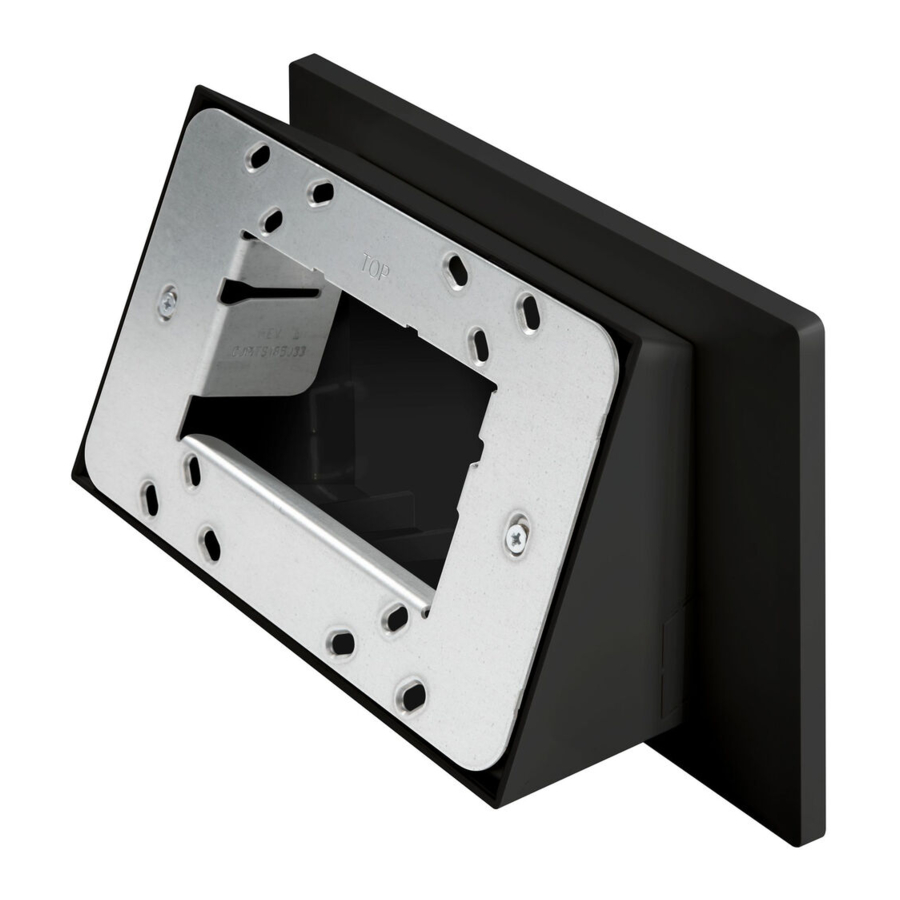
- Attach the rear faceplate to the wall:
NOTE: Ensure that the rear faceplate is oriented so that the "TOP" machined text is facing upward prior to installation. Also ensure that the faceplate is level after installation.
- For U.S.-style installations, use the four provided 6-32 x 1 in. screws to install the rear faceplate over a 2-gang, or 3-gang U.S. electrical box (as shown in the following illustration).
- For European-style installations, use the four provided M3 x 25 mm screws to install the rear faceplate over a 2-gang European electrical box.
Multisurface Mount Kit for TSW-770 and TSW-1070 Series, Angled
- For U.K.-style installations, use the two provided M3.5 x 25 mm l screws to install the rear faceplate over a 2-gang U.K. electrical box.

![information]() NOTE: Four washers are provided to secure the faceplate to the electrical box if the mounting holes are too large for the included screws.
NOTE: Four washers are provided to secure the faceplate to the electrical box if the mounting holes are too large for the included screws.

- Press the front faceplate into the rear faceplate until it snaps into place.
NOTE: Ensure that the front faceplate is oriented so that the "TOP" machined text is facing upward prior to installation. Also ensure that the faceplate is level after installation.

l For U.K.-style installations, use the two provided M3.5 x 25 mm 3. Press the front faceplate into the rear faceplate until it snaps into screws to install the rear faceplate over a 2-gang U.K. electrical place. box.
NOTE: If the front faceplate needs to be removed, insert the tip of a flathead screwdriver (or similar tool) into the machined notches on the bottom of the faceplate, and then carefully push against the faceplate to pop it off. Refer to the following image for the location of the notches. |
- Attach the angled bracket to the front faceplate using the four provided 6-32 x 1/2 in. screws.


- Attach the TSW-770/1070 mounting bracket (provided with the touch screen) to the angled bracket using the two provided 6-32 x 3/8 in. screws. Ensure the bracket is level after installation.
NOTE: If installing a TSW-770-LB or TSW-1070-LB light bar as part of the MSMK installation, the light bar must be placed in between the TSW-770/1070 mounting bracket and the MSMK angled bracket during this stage of the installation. The two provided 6-32 x 3/4 in. screws must also be used in place of the 6-32 x 3/8 in. screws. For more information on installing the light bar, refer to the TSW-770-LB and TSW-1070-LB Quick Start.

- Route all cables out of the center openings in the faceplates and brackets and connect them to the rear of the touch screen.
- After all connections have been made, hold the touch screen over the mounting plate and place it gently in position so that it attaches securely to the plate.
For more information on connecting the touch screen, refer to the TSW-570, TSW-770, and TSW-1070 Product Manual or the TSS-770 and TSS-1070 Product Manual.
Drywall Mounting
- Create a cutout in the drywall where the touch screen will be installed for routing cables.
- Route all necessary cables through the drywall cutout.
- Attach the angled bracket to the drywall surface using four standard drywall anchors and 6-AB x 1 in. drywall screws (not included).
NOTE: Ensure the angled bracket is level after installation.
- Attach the TSW-770/1070 mounting bracket (provided with the touch screen) to the angled bracket using the two provided 6-32 x 3/8 in. screws. Ensure the bracket is level after installation.
NOTE: If installing a TSW-770-LB or TSW-1070-LB light bar as part of the MSMK installation, the light bar must be placed in between the TSW-770/1070 mounting bracket and the MSMK angled bracket during this stage of the installation. The two provided 6-32 x 3/4 in. screws must also be used in place of the 6-32 x 3/8 in. screws. For more information on installing the light bar, refer to the TSW-770-LB and TSW-1070-LB Quick Start.
- Route all cables out of the center opening in the angled bracket and connect them to the rear of the touch screen.
- After all connections have been made, hold the touch screen over the mounting plate and place it gently in position so that it attaches securely to the plate.
Surface Mounting
Use the following procedures to mount the MSMK onto a flat pane of glass or a similar smooth surface (such as granite, marble, plaster, or smooth stone and masonry). The included adhesive pad attaches permanently to the surface.
The following is required for this installation: a level, masking tape, a Phillips screwdriver, and isopropyl alcohol (minimum 70%).

Observe the following points to ensure the MSMK properly bonds to the mounting surface. Failure to properly bond the MSMK to the mounting surface could cause the MSMK to detach after installation.
- Use isopropyl alcohol (minimum 70%) to clean the mounting surface. Other surface cleaning products can leave a film that will prevent the adhesive from properly bonding to the mounting surface.
- Use a new, clean nonlinting cloth to apply the isopropyl alcohol. The cloth should not have been used with any other cleaning product to ensure that it does not leave a film on the mounting surface.
- Allow the isopropyl alcohol to air dry on the mounting surface for at least one minute before applying adhesive. Do not dry the surface with a cloth prior to applying adhesive.
- Do not apply adhesive to the mounting surface in temperatures below 65°F (19°C).
- When mounting on glass surface, make sure the glass does not have any coating or film application.
Attach the Angled Bracket to the Mounting Surface
- Select a mounting location for the MSMK and determine whether raceway (not included) will be entering the MSMK from the top, bottom, left, or right cutout.
- Use pliers (or a similar tool) to break away the appropriate knockout on the left, right, or bottom of the angled bracket for running cables to the touch screen.
- Clean and dry the mounting surface thoroughly. Refer to the caution statements at the beginning of the "Surface Mounting" section for important cleaning and drying notes.
- Using the level, tape a horizontal reference line on the glass surface that aligns with the lower edge of the angled bracket. Ensure the reference line is level before proceeding.
- Remove the protective backing from the adhesive pad attached to the angled bracket.
- Hold the angled bracket at a 45-degree angle to the glass surface, and then align the lower edge of the bracket with the taped reference line. Do not allow the adhesive to come in contact with the glass surface yet.
- Once the angled bracket is level and aligned with the taped reference line, press the bracket to the mounting surface firmly to ensure proper adhesion and to eliminate any trapped air bubbles. Press and hold the outer edges and interior surfaces of the bracket against the surface for at least 30 seconds to ensure the adhesive bonds to the surface.
NOTE: All air bubbles must be smoothed out and eliminated to ensure a complete bond to the surface.

Allow a minimum of 24 hours for the adhesive to cure to the surface before installing the TSW-770/1070 Mounting Bracket. Failure to properly cure the bracket to the mounting surface could cause the MSMK to detach after installation.
Attach the TSW-770/1070 Mounting Bracket
- Remove any existing tape guides and install any raceway (not included) to conceal cables running to the desired knockout on the angled bracket.
NOTE: To ensure the raceway fits into the knockout, Crestron recommends using raceway with the following dimensions: 0.45 H x 0.77 in. W (11 x 20 mm).
- Attach the TSW-770/1070 mounting bracket (provided with the touch screen) to the angled bracket using the two provided 6-32 x 3/8 in. screws. Ensure the bracket is level after installation.
NOTE: If installing a TSW-770-LB or TSW-1070-LB light bar as part of the MSMK installation, the light bar must be placed in between the TSW-770/1070 mounting bracket and the MSMK angled bracket during this stage of the installation. The two provided 6-32 x 3/4 in. screws must also be used in place of the 6-32 x 3/8 in. screws. For more information on installing the light bar, refer to the TSW-770-LB and TSW-1070-LB Quick Start.

Attach the Touch Screen 5.
- Route all cables through the chosen knockout and out of the center opening in the angled bracket, and then connect them to the rear of the touch screen.
- After all connections have been made, hold the touch screen over the mounting plate and place it gently in position so that it attaches securely to the plate.
Attach the Label (Optional)
To provide a finished appearance for installations on glass or other transparent surfaces, install the included polycarbonate label on the opposite side of the surface behind the MSMK. To install the label:
- Clean and dry the rear of the mounting surface thoroughly. Refer to the caution statements at the beginning of the "Surface Mounting" section for important cleaning and drying notes.
- Using the level, tape a horizontal reference line on the glass surface that aligns with the lower edge of the angled bracket on the opposite side. Ensure the reference line is level before proceeding.
- Remove the protective liner from the rear of the label.
The adhesive on the rear of the label is high-strength bond. Once the adhesive comes in contact with a surface, it cannot be removed easily.
- Hold the label at a 45-degree angle to the angled bracket, and then align the lower edge of the label with the lower edge of the bracket. Do not allow the label adhesive to come in contact with the surface.
- Once the label is level and aligned with the angled bracket, attach the label to the mounting surface carefully. Press and hold the label against the surface for at least 30 seconds to ensure the adhesive bonds to the surface.
NOTE: All air bubbles must be smoothed out and eliminated to ensure a complete bond to the surface.

Visit the Product Page
Scan the QR code to visit the product page.
TSW-770/1070-MSMK-ANG

www.crestron.com/model/6511786
Additional Information
Original Instructions
The U.S. English version of this document is the original instructions. All other languages are a translation of the original instructions.
Crestron product development software is licensed to Crestron dealers and Crestron Service Providers (CSPs) under a limited nonexclusive, nontransferable Software Development Tools License Agreement. Crestron product operating system software is licensed to Crestron dealers, CSPs, and end-users under a separate End-User License Agreement. Both of these Agreements can be found on the Crestron website at www.crestron.com/legal/software_license_agreement.
The product warranty can be found at www.crestron.com/warranty.
The specific patents that cover Crestron products are listed at www.crestron.com/legal/patents.
Certain Crestron products contain open source software. For specific information, visit www.crestron.com/opensource.
Documents / Resources
References
![www.crestron.com]() TSW-770/1070-MSMK-ANG-B-S [Crestron Electronics, Inc.]
TSW-770/1070-MSMK-ANG-B-S [Crestron Electronics, Inc.]![www.crestron.com]() TSW-770-B-S [Crestron Electronics, Inc.]
TSW-770-B-S [Crestron Electronics, Inc.]![www.crestron.com]() TSS-770-B-S [Crestron Electronics, Inc.]
TSS-770-B-S [Crestron Electronics, Inc.]![www.crestron.com]() TSW-1070-B-S [Crestron Electronics, Inc.]
TSW-1070-B-S [Crestron Electronics, Inc.]![www.crestron.com]() TSS-1070-B-S [Crestron Electronics, Inc.]
TSS-1070-B-S [Crestron Electronics, Inc.]![www.crestron.com]() Software License Agreements (Embedded Software and Software Tools) [Crestron Electronics, Inc.]
Software License Agreements (Embedded Software and Software Tools) [Crestron Electronics, Inc.]![www.crestron.com]() Standard Terms & Conditions and Warranties [Crestron Electronics, Inc.]
Standard Terms & Conditions and Warranties [Crestron Electronics, Inc.]![www.crestron.com]() Patents [Crestron Electronics, Inc.]
Patents [Crestron Electronics, Inc.]![www.crestron.com]() Open Source Software [Crestron Electronics, Inc.]
Open Source Software [Crestron Electronics, Inc.]
Download manual
Here you can download full pdf version of manual, it may contain additional safety instructions, warranty information, FCC rules, etc.
Download Crestron TSW-770 / TSW-1070 Series, TSW-770-MSMK-ANG, TSW-1070-MSMK-ANG Manual
Advertisement


Need help?
Do you have a question about the TSW-770 Series and is the answer not in the manual?
Questions and answers