
Related Manuals for Ruijie Reyee RG-EST450G


Summary of Contents for Ruijie Reyee RG-EST450G
- Page 1 Ruijie Reyee RG-EST450G Wireless Bridge Installation Guide Document Version: V1.1 Date: March 28, 2025 Copyright © 2025 Ruijie Networks...
- Page 2 All rights are reserved in this document and this statement. Any reproduction, excerption, backup, modification, transmission, translation or commercial use of this document or any portion of this document, in any form or by any means, without the prior written consent of Ruijie Networks is prohibited.
-
Page 3: Preface
Preface Audience This document is intended for: Network engineers Technical support and servicing engineers Network administrators Technical Support Official Website of Ruijie Reyee: https://reyee.ruijie.com Technical Support Website: https://reyee.ruijie.com/en-global/support Case Portal: https://www.ruijienetworks.com/support/caseportal Community: https://community.ruijienetworks.com ... - Page 4 Note An alert that contains additional or supplementary information that if not understood or followed will not lead to serious consequences. Specification An alert that contains a description of product or version support. Note This document provides the installation steps, troubleshooting, technical specifications, as well as the specifications and use guidelines of cables and connectors.
-
Page 5: Table Of Contents
Contents Preface ..............................I 1 Product Introduction ........................... 1 1.1 Overview ............................ 1 1.2 Package Contents........................1 1.3 Appearance ..........................2 1.3.1 Appearance ........................2 1.3.2 Ports, Buttons and LEDs ....................4 1.4 Technical Specifications ......................6 1.5 Power Supply Technical Specifications ..................8 2 Preparing for Installation ........................ - Page 6 3.2 Before You Begin ........................13 3.3 Safety Precautions During Installation ..................14 3.4 Mounting the Device ........................ 14 3.4.1 Wall Mounting ......................14 3.4.2 Pole Mounting ......................15 3.5 Connecting Cables........................16 3.6 Verifying the Installation ......................18 4 Debugging ............................19 4.1 Power-On ..........................
-
Page 7: Product Introduction
Product Introduction Overview The RG-EST450G wireless bridge is launched by Ruijie Reyee. It utilizes the IEEE 802.11ac standard for efficient and reliable communication. Operating in the 5 GHz band and supporting 2x2 MIMO technology, this product delivers a maximum wireless rate of 867 Mbps for bridging services, ensuring more than sufficient bandwidth for delivering point to point (PTP) and point to multi-point (PTMP) services. -
Page 8: Appearance
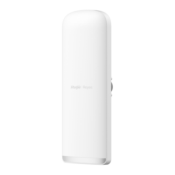
Installation Guide Product Introduction Appearance 1.3.1 Appearance Figure 1-1 Appearance of the RG-EST450G Wireless Bridge Front view Back view... - Page 9 Installation Guide Product Introduction Note The label is located on the back of the device.
-
Page 10: Ports, Buttons And Leds
Installation Guide Product Introduction 1.3.2 Ports, Buttons and LEDs Figure 1-2 Ports, Buttons and LEDs of the RG-EST450G Wireless Bridge Table 1-2 Ports, Buttons and LEDs of the RG-EST450G Wireless Bridge Mark Item Description 7 status LEDs, including 1 x system LED, 3 x port LEDs and Status LEDs 3 x signal LEDs 12 V DC connector... - Page 11 Installation Guide Product Introduction Mark Item Description Press and hold the button for less than 2s: The wireless bridge pairs with another wireless bridge (the LED blinks during pairing). Reset/One-Touch Pairing Press and hold the button for 2s to 10s: No action is button triggered.
-
Page 12: Technical Specifications
Installation Guide Product Introduction Status Description LED 1 on The RSSI is above –75 dBm. LED 1 on, LED 2 blinking The RSSI is above –73 dBm. The RSSI is above –71 dBm. LEDs 1 and 2 on The RSSI is above –68 dBm. LEDs 1 and 2 on, LED 3 blinking The RSSI is above –64 dBm. - Page 13 Installation Guide Product Introduction Model RG-EST450G Data Rate 2.4 GHz: 150 Mbps 5 GHz: 867 Mbps Modulation OFDM: BPSK@6/9 Mbps, QPSK@12/18 Mbps, 16-QAM@24/36 Mbps, 64-QAM@48/54 Mbps Technology MIMO-OFDM: BPSK, QPSK, 16-QAM, 64-QAM, 256-QAM Receive Sensitivity 11a: -89 dBm (6 Mbps), –80 dBm (24 Mbps), –76 dBm (36 Mbps), – 71dBm (54 Mbps) 11n: –83 dBm@MCS0, –65 dBm@MCS7, –83 dBm@MCS8, –...
-
Page 14: Power Supply Technical Specifications
Installation Guide Product Introduction Warning Operation of this equipment in a residential environment could cause radio interference. Note The weight refers to the weight of the main unit. Power Supply Technical Specifications The RG-EST450G can be powered by 12 V/1.2 A DC power supply, 24 V passive PoE power supply, and IEEE 802.3at/af-compliant PoE power supply. -
Page 15: Preparing For Installation
Installation Guide Preparing for Installation Preparing for Installation Safety Precautions Note To prevent device damage and physical injury, please read carefully the safety precautions described in this chapter. The following safety precautions do not cover all possible dangers. 2.1.1 General Safety Precautions ... -
Page 16: Installation Environment Requirements
Installation Guide Preparing for Installation Installation Environment Requirements To ensure normal operation and a prolonged service life of the device, the installation site must meet the following requirements. 2.2.1 Environment Install the device in a well-ventilated environment. If it is installed in a closed room, make sure there is a good cooling system. -
Page 17: Surge Protection
Installation Guide Preparing for Installation Distance Between Base Station Recommended Installation Bridge Type and Customer Premises Height (Above the Obstacle) Equipment (CPE) 500 m (1640.42 ft.) 4 m (13.12 ft.) 2.2.2 Surge Protection When the connection cable between the main grounding conductor and local equipotential earthing terminal board (LEB) on each floor is short, use a stranded copper wire with a sectional area not less than 1.318 mm2 (16 AWG) for the connection cable. -
Page 18: Tools
Installation Guide Preparing for Installation devices. Tools Table 2-2 Tools Common Marker, Phillips screwdriver, hammer drill, power cords, Ethernet cables, and diagonal plier Tools Anti-ESD gloves, wire stripper, crimping plier, RJ45 crimping plier, wire cutter, and Special Tools waterproof adhesive tape Meters Multimeter Relevant... -
Page 19: Installation
Installation Guide Installation Installation Caution Before installing the device, make sure that you have carefully read the requirements described in Chapter 2. Installation Procedure Before You Begin Carefully plan and arrange the installation location, networking mode, power supply, and cabling of the device before installation. -
Page 20: Safety Precautions During Installation
Installation Guide Installation Safety Precautions During Installation To ensure minimal interference when installing multiple wireless bridges in close proximity, maintain a horizontal installation distance of at least 2 meters (6.56 ft), or a vertical installation distance of at least 0.5 meters (1.64 ft) between each wireless bridge. -
Page 21: Pole Mounting
Installation Guide Installation 3.4.2 Pole Mounting (1) Install the device to the mounting bracket. (2) Secure the mounting bracket to the pole by threading a clamp through the mounting bracket. (3) Adjust the orientation. -
Page 22: Connecting Cables
Installation Guide Installation Connecting Cables (1) Select or make an Ethernet cable suitable for the distance between the bridge and the power source equipment. (The bridge supports Cat5e or higher cables up to 100 meters (328.08 ft) for PoE power supply.) (2) Connect one end of the Ethernet cable to the PoE port of the 1000 Mbps passive PoE injector, and the other end to the LAN1/PoE port on the bridge. - Page 23 Installation Guide Installation Figure 3-2 Connect the Ethernet cable to a solar panel Solar Panel Solar panels convert light energy from sunlight into electrical energy. The EST350G requires a solar power panel with an output specification of 12V/1.2A DC. Notes for Installing the Solar Panel Because the sun’s position differs between the Northern and Southern Hemispheres, the solar panel should face south in the Northern Hemisphere and north in the Southern Hemisphere to achieve optimal power output.
-
Page 24: Verifying The Installation
Installation Guide Installation Do not use other models of PoE injectors or switches for power supply as it may lead to irreparable damage to the device. Verifying the Installation (1) Check the device Verify that the external power supply matches the specification. ... -
Page 25: Debugging
Method 1: Configure the bridge through Ruijie Reyee App (1) The power cord is properly connected. (2) Scan the QR code on this page or on the device to download and install Ruijie Reyee App. (3) Log in to Ruijie Reyee App. -
Page 26: Monitoring And Maintenance
Installation Guide Monitoring and Maintenance Monitoring and Maintenance Monitoring You can observe the LED status to monitor the device in operation. Hardware Maintenance If the hardware is faulty, please contact Ruijie Networks technical support for assistance. -
Page 27: Common Troubleshooting
Hardware Installation and Reference Guide Common Troubleshooting Common Troubleshooting Troubleshooting Flowchart... -
Page 28: Appendix
Hardware Installation and Reference Guide Appendix Appendix Connectors and Media 1000BASE-T/100BASE-TX/10BASE-T Port The 1000BASE-T/100BASE-TX/10BASE-T port is a 10/100/1000 Mbps auto-negotiation port that supports auto MDI/MDIX Crossover. Compliant with IEEE 802.3ab, the 1000BASE-T port requires Category 5e 100-ohm UTP or STP (recommended) with a maximum distance of 100 meters (328 feet). - Page 29 Hardware Installation and Reference Guide Appendix The following figure shows feasible connections of the straight-through and crossover twisted pair cables for a 100BASE-TX/10BASE-T port. Figure 7-2 100BASE-TX/10BASE-T Twisted Pair Connections St raight -Through Cr ossover Switch Adapter Switch Switch...
Need help?
Do you have a question about the Reyee RG-EST450G and is the answer not in the manual?
Questions and answers