
Related Manuals for Ruijie Reyee RG-EG105G-V3


Summary of Contents for Ruijie Reyee RG-EG105G-V3
- Page 1 Ruijie Reyee RG-EG105G-V3 Router Hardware Installation and Reference Guide Document Version: V1.0 Date: March 29, 2024 Copyright © 2024 Ruijie Networks...
- Page 2 Due to product version upgrades or other reasons, the content of this document will be updated from time to time. Ruijie Networks reserves the right to modify the content of the document without any notice or prompt. This manual is for reference only. Ruijie Networks endeavors to ensure content accuracy and will not shoulder...
-
Page 3: Preface
Intended Audience This document is intended for: Network engineers Technical support and servicing engineers Network administrators Technical Support Official website of Ruijie Reyee: https://reyee.ruijie.com Technical Support Website: https://reyee.ruijie.com/en-global/support Case Portal: https://www.ruijienetworks.com/support/caseportal Community: https://community.ruijienetworks.com ... - Page 4 Note This manual provides the device installation steps, hardware troubleshooting, module technical specifications, and specifications and usage guidelines for cables and connectors. It is intended for the users who have some experience in installing and maintaining network hardware. At the same time, it is assumed that the users are already familiar with the related terms and concepts.
-
Page 5: Table Of Contents
Contents Preface ..............................I 1 Product Overview ..........................1 1.1 Specifications ..........................1 1.2 Appearance ..........................2 1.3 Power Supply ..........................3 1.4 Heat Dissipation ......................... 4 1.5 Port ............................. 4 1.6 LED Indicator ..........................4 2 Preparing for Installation ........................5 2.1 Safety Precautions ........................ - Page 6 3.1 Installation Procedure ......................10 3.2 Preparing..........................11 3.3 Precautions ..........................11 3.4 Installing the Device ......................... 11 3.4.1 Mounting the Router to a Workbench ................11 3.4.2 Mounting the Device on the Wall ................. 12 3.5 Connecting the Power Supply ....................13 3.6 Connecting Cables........................
- Page 7 6 Appendix ............................19 6.1 Connectors and Connection Media ..................19 6.2 Cabling Recommendations in Installation ................20 6.2.1 Requirement for the minimum cable bend radius ............20 6.2.2 Requirement for the minimum fiber bend radius ............20 6.2.3 Precautions for Bundling up Cables ................21...
-
Page 8: Product Overview
Product Overview Featured with global-leading semiconductor technologies and communication control technologies, Ruijie RG- EG105G-V3 router is a data communication product developed by Ruijie Networks with independent intellectual property right. The RG-EG105G-V3 router is designed according to international standards, similar to the mainstream router products in the international market. -
Page 9: Appearance
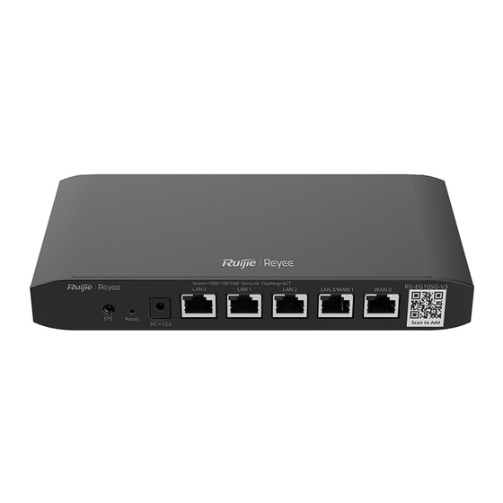
206.5 mm x 28 mm x 108.5 mm (8.13 in. x 1.1 in. x 4.27 in.) (W x H x D) Weight 0.55kg Warning Operation of this equipment in a residential environment could cause radio interference. Caution Use the power adapter provided by Ruijie. Appearance Figure 1-1 Appearance of RG-EG105G-V3... -
Page 10: Power Supply
Hardware Installation and Reference Guide Product Overview Figure 1-2 Front Panel of RG-EG105G-V3 Mark Item Mark Item System status LED LAN ports Reset button LAN/WAN port Power supply WAN port Caution Reset button: Press the button for less than 2 seconds, the system will restart; press for more than 5 seconds until the system status LED blinks, the system will restore the factory settings and restart. -
Page 11: Heat Dissipation
System LED Blinking green (0.5Hz): The device is not connected to Ruijie Cloud. Solid green: The device has started up, and is connected to Ruijie Cloud. Blinking green (10Hz): The device is restoring the factory settings or starting up. Solid green: The port is up. -
Page 12: Preparing For Installation
Hardware Installation and Reference Guide Preparing for Installation Preparing for Installation Safety Precautions Note ● To avoid personal injury and equipment damage, please carefully read the safety suggestions before you install the RG-EG105G-V3 router. ● The following safety precautions may not cover all possible dangers. 2.1.1 Installation ... -
Page 13: Static Discharge Damage Prevention
Hardware Installation and Reference Guide Preparing for Installation greater than twice of the theoretical maximum leakage current of all the power supplies in the system. For example, if a system is equipped with eight identical power supplies, the leakage current of each power supply is equal to or less than 3.5 mA, and the leakage current of the system totals 56 mA. -
Page 14: Ventilation
Hardware Installation and Reference Guide Preparing for Installation 2.2.2 Ventilation For the router, a sufficient space (at least 10 cm distances from both sides and the back plane of the workbench) should be reserved at the ventilation openings to ensure the normal ventilation. After various cables have been connected, they should be arranged into bundles or placed on the cabling rack to avoid blocking the air inlets. -
Page 15: Emi
Hardware Installation and Reference Guide Preparing for Installation Table 2-1 Requirements for the Dust Content and Granularity in the Equipment Room Dust Unit Density Diameter ≥ 0.5 μ m ≤ 3.5 × 10 Particles/m Diameter ≥ 5 μ m ≤ 3 × 10 Particles/m Apart from dust, the salt, acid and sulfide in the air in the equipment room must also meet strict requirements, as such poisonous substances may accelerate the corrosion of the metal and the aging of some parts. -
Page 16: Mounting
Hardware Installation and Reference Guide Preparing for Installation Measures must be taken to shield static electricity. 2.2.6 Mounting The router supports wall mounting. The recommended screws and wall anchors are listed in the following table. Type Specification Quantity Pan-head self-tapping screw with cross recess ST4.2*20PWA-9mm Plastic wall anchor 4*20 wall anchor for self-tapping screw... -
Page 17: Installing The Router
Hardware Installation and Reference Guide Installing the Router Installing the Router Caution Ensure that requirements in Chapter 2 are all met. Installation Procedure The installation steps are shown in the following figure. Figure 3-1 Installation Procedure Prepare for installation Read precautions Install the device Ground the device Connect the power supply... -
Page 18: Preparing
Hardware Installation and Reference Guide Installing the Router Preparing Carefully plan and arrange the installation position, networking mode, power supply and cabling before installation. Confirm the following requirements before installation: The installation site provides sufficient space for heat dissipation. ... -
Page 19: Mounting The Device On The Wall
Hardware Installation and Reference Guide Installing the Router 3.4.2 Mounting the Device on the Wall RG-EG105G-V3 can be mounted on the wall. (Mounting screws and wall anchors are customer-supplied.) In actual installation, users need to determine the size and depth of the two mounting holes on the wall based on the sizes of wall anchors and screws. -
Page 20: Connecting The Power Supply
Hardware Installation and Reference Guide Installing the Router Figure 3-2 Mounting the Router on the Wall Caution The device can be mounted only on the concrete or other non-combustible walls. Connecting the Power Supply RG-EG105G-V3 router uses 2-conductor power cables. You are suggested to use a single-phase 2-conductor outlet or a multifunction microcomputer outlet with neutral connector. -
Page 21: Connecting Cables
Hardware Installation and Reference Guide Installing the Router Caution ● Please use the power supply adapter delivered with the device to prevent accidents. ● The maintenance personnel should check whether the AC socket is reliably connected to the protection ground of the building. If not, the maintenance personnel should use a protection ground wire to connect the protection ground terminal of the AC socket to the protection ground of the building. - Page 22 Hardware Installation and Reference Guide Installing the Router...
-
Page 23: System Debugging
Connect the PC to the LAN port of the router, and configure the PC to obtain an IP address automatically. Or connect the cable of AP to the LAN port of the router. After the AP is powered on, it will broadcast the SSID starting with @Ruijie-m. You can connect to the SSID for configuration. Figure 4-1... -
Page 24: Log In To The Web Interface
Hardware Installation and Reference Guide System Debugging Log In to the Web Interface (1) Start up the PC and configure the local connection attribute on the PC. Change the static IP address of the PC to 192.168.110.XXX (1–255, excluding 1). Figure 4-2 Change the IP Address of the PC (2) Open a browser, enter 192.168.110.1 into the address bar of the browser, and press Enter. -
Page 25: Maintenance And Troubleshooting
Hardware Installation and Reference Guide Maintenance and Troubleshooting Maintenance and Troubleshooting General Troubleshooting Procedure Troubleshooting Common Faults Symptom Possible Causes Solution Press the Reset Button for more than password manually Forgetting the login password 5 seconds to restore the default configured but it is forgotten. -
Page 26: Appendix
Hardware Installation and Reference Guide Appendix Appendix Connectors and Connection Media 1000BASE-T/100BASE-TX/10BASE-T Ports The 1000BASE-T/100BASE-TX/10BASE-T is a port that supports adaptation of three rates, and automatic MDI/MDIX Crossover at these three rates. The 1000BASE-T complies with IEEE 802.3ab, and uses the cable of 100-ohm Category-5 or Supper Category- 5 UTP or STP, which can be up to 100 m. -
Page 27: Cabling Recommendations In Installation
Hardware Installation and Reference Guide Appendix Figure A-3 Connections of the Twisted Pairs of the 100BASE-TX/10BASE-T Optical Fiber Connection For the optical fiber ports, select single-mode or multiple-mode optical fibers for connection according to the fiber module connected. The connection schematic diagram is shown in Figure A-4: Figure A-4 Optical Fiber Connections Cabling Recommendations in Installation When the device is installed in standard 19-inch cabinets, the cables are tied in the binding rack on the cabinet... -
Page 28: Precautions For Bundling Up Cables
Hardware Installation and Reference Guide Appendix diameter of the fiber. 6.2.3 Precautions for Bundling up Cables Before bundling cables, correctly mark labels and stick the labels to cables where appropriate. Cables should be neatly and properly bundled, as shown in Figure B-1. Figure B-1 Bundling Up Cables (1) ... - Page 29 Hardware Installation and Reference Guide Appendix Figure B-2 Bundling Up Cables (2) When cables need to bend, you should first bundle them up. However, the buckle cannot be bundled within the bend area. Otherwise, significant stress may be generated in cables, breaking cable cores. As shown in Figure B-3.
- Page 30 Hardware Installation and Reference Guide Appendix Figure B-4 Cable Fastening The hard power cable should be fastened by the terminal connection area to prevent stress. Do not use self-tapping screws to fasten terminals. Power cables of the same type and in the same cabling direction should be bundled up into cable bunches, with cables in cable bunches clean and straight.
Need help?
Do you have a question about the Reyee RG-EG105G-V3 and is the answer not in the manual?
Questions and answers