
Related Manuals for Mountup MU6012A


Summary of Contents for Mountup MU6012A
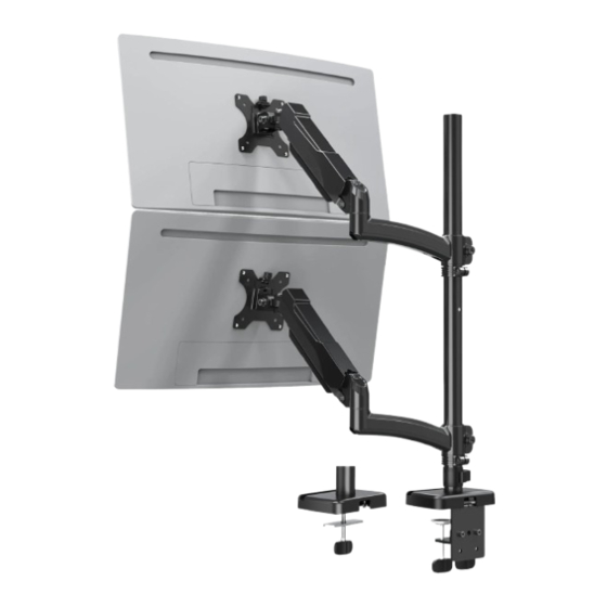
- Page 1 Dual Monitor Desk Mount Instruction Manual Each Monitor: 75×75mm 4.4 Ibs ~ 19.8 Ibs Load 100×100mm Capacity (2kg ~ 9kg) AHP-D42H-13_US2.0 If you have any questions, please feel free to contact our customer support before returning.
-
Page 2: Safety Caution
Safety Caution BEFORE ASSEMBLY ● Layout all components and hardware. Check all parts are included and undamaged. ● Should anybody intends to install or use this mount, please read and understand this manual carefully. ● If you do not understand these instructions or have any doubt about the safety instructions, assembly or use of this product, please contact our customer service. -
Page 3: Assembly Steps
ASSEMBLY STEPS STEP 1: Apply Pads to the Base Bottom Apply the pads (E) onto the bottom of lower pole (3A) to avoid desk scratches. STEP 2: Clamp Installation or Grommet Base Installation OPTION A : Clamp Installation 1. Connect the base of lower pole (3A) and the L plate (06) by using the screws (A). 2. - Page 4 STEP 2: Continued Fix the decorative cover (04) to the base of lower pole (3A) and fix the bracket on the table by tightening the clamp (07). 0.39~3.15" (10~80mm) OPTION B: Grommet Base Installation Detach the bolt (7-3) from the clamp (07). Use the bolt (7-3) through the hole on support plate (05) to fix the lower pole (3A) and the table board together.
-
Page 5: Step 3: Pole Installation
STEP 3: Pole Installation Assemble the lower pole (3A) and the upper pole (3B) together. Secure the pole assembly with the preassembled screw (I) and Allen key (D3). Tighten... -
Page 6: Step 4: Arm Installation
STEP 4: Arm Installation Install the cable clip (G), fixator (H) and arm (1A) to the pole as shown below. Then fasten the bolts with Allen key (D1, D2). - Page 7 STEP 5: Attach Monitor OPTION A: Flat Back Monitor Attach the VESA plate (02) to back of monitor Please make sure you don’t tighten and secure it with screws and waswhers by the screws much excessively or it may cause your monitor damage. using Allen key (D1).
- Page 8 STEP 6: Hang Monitor Slide the monitor onto the head of arm (1A), then install the security bolts (F). Make sure the security bolts (F) is installed before you rotate the monitor. Attention: The initial pressure value of the gas spring is set to a minimum value.
-
Page 9: Step 7: Tension Adjustment
STEP 7: Tension Adjustment For intended functioning of the mount, you will need to adjust the tension of arm in accordance with your monitor weight by 6mm Allen key (D2). Note: If the bolt is covered over, please hold the upper arm and press it down to maintain a horizontal position, and then you can see the adjustment screw at the joint. -
Page 10: Step 8: Cable Management
STEP 8: Cable Management Run cables through the cable cover. Upper Arm Run cables through the cable cover (1B), then insert the cable cover into the upper arm. Lower Arm 1.Remove the bottom cable cover by using a Allen key (D1). 2.Run cables through the cable cover. - Page 11 Adjust as Desired Adjust monitor position and rotation. Store Allen keys in cable clip for future use. Tilt Swivel Rotation Height DESK DESK Please do not move stand outside desk for safety! Note: To ensure stability, the tightness of the rotating axis has been preset, so it would be kind of difficult to rotate the VESA plate.
-
Page 12: Product Dimensions
Product Dimensions ±90° 11.4" (290mm) MAX: 36.3" (922mm)
Need help?
Do you have a question about the MU6012A and is the answer not in the manual?
Questions and answers