Table of Contents
Advertisement
Quick Links
Advertisement
Table of Contents

Related Manuals for Mountup MU0021


Summary of Contents for Mountup MU0021
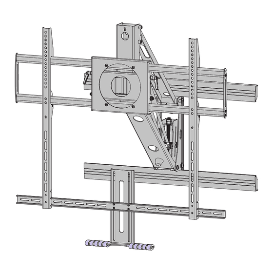
- Page 1 MU0021 INSTALLATION INSTRUCTION Mantel Arm Mount Max:800x600mm/32x24" WEIGHT: 55"~100" 44~143LBS Min: 300x200mm/12x8" 20~65KG This bracket is made of recyclable steel. (A3) If you have any questions, please contact us via help@jollyholding.com...
- Page 2 Sufficient expertise is required for installing of this product. Be sure to subcontract the installation to a qualified person. Ensure special attention to safety is paid during installation. MOUNTUP mount is not liable for any damage or injury caused by mishandling or improper installation, or by installing anything other than the specified product.Your statutory rights, (if any) are not affected.
-
Page 3: Table Of Contents
Tools Needed for Assembly Required Tools 3/16” 3/8” Optional Tools Before you begin, please verify that all components are included and undamaged. If any parts are missing or damaged,contact Product Supplier,Never proceed with missing or damaged parts! Lay out all components and make sure you identify that each one has a match in the diagram.Some of the parts included will not be used during installation. -
Page 4: Parts List
Before you b egin, make sure all parts shown are included with your product. Parts may appear slightly different than illustrated. Parts List Description 15x15x40 philips pan head screw M6x12 philips pan head screw M6x25 philips pan head screw M8x12 philips pan head screw M8x25 washer(1) -
Page 5: Critical Requirements Of The Installation
CRITICAL requirements of the installation WARNING • Make sure that the supporting surface will safely support the combined load of the equipment and all attached hardware and components, Bracket installation need two people together to complete. If the main wall is wooden,There must be at least 2 studs Temperature at the front edge of mantle should available for mounting.If the main wall is concrete or brick never exceed 110°... -
Page 6: Installation Of The Bracket
Installation of the bracket Locate at least two studs with a stud finder. Locate the Measure the centerline of the mantle. Mark center of these studs by using a sharp awl or finish nail with tape on the wall. poked through the drywall to locate each edge. Lag bolts must be installed into the CENTER of the studs. - Page 7 Installation of the bracket Please reference point 5 at page 5 to punch,If the main wall is concrete or brick wall, you must use the expansion pipe we provided in M. In order to have a better installa- tion,it is necessary to inlay one wire cassette on the wall.
- Page 8 Installation of the bracket Take out K/EE/FF/N(spanner M10) from the packaging , installation as illustrated in the picture. keep the up direction uniform (spanner M10) Take out N/J from the packaging ,lock the four allen pan head screws(M8x10) with Hexagon wrench in N,then use cable ties in N to tie up the wires,as is shown in the pictures below.
-
Page 9: Installation Of Screen
Installation of Screen Select TV Screws Thread screws by hand into the threaded holes on the back of your TV to select which screw diameter fits your TV. When attaching brackets to the flat screen,be careful not to over tighten screws and be sure that screws do not bottom out in the mounting holes. - Page 10 Attach the Hooks Position your hooks over your TV hole pattern - making sure the hooks are centered and level over the TV hole pattern. Secure the hooks using your screw/washer/spacer selection: (a) for Flat Back (b) for Round Back/Extra space CAUTION: Ensure hook is securely fastened before moving on to the next step.
- Page 11 Attach the Handle Take out H/I/AA/DD from the packaging,according to the size of the TV,adjust to the appropriate location,as shown in the picture below,then lock with cross screwdriver. Note: Take care not to damage the TV when putting the connecting rod(DD) into the small gap of the hook(BB). Lift the TV,through hooks for hanging onto the bracket panel,then press the Take out GG from the packaging,...
-
Page 12: Adjustment Of The Spring Pressure
adjustment of the spring pressure Adjust the spring pressure to the appropriate level with the socket wrench and O1 or O2 (the hexagon wrench M8 that we provided). KG/LBS 18.0/40.0 STOP LINE 24.0/52.9 32.0/70.5 Refer to this above cylinder as a pointer 40.0/88.2 Adjustable the bracket’s constant force Attention: The weight of the TV set in the weighing range... -
Page 13: Leveling Adjustment
WARNING: Do Not put hands into Lifting Mechanism. The power of the Lifting Mechanism can cause bodily injury! TV leveling adjustment (-5°/+5°) If needed,loosen 4 leveling nuts on the rear of TV plate by maximum 2 turns with the N(spanner), adjust to level, and retighten to secure. ±5°... -
Page 14: Tilting Angle Adjustment
Tilting angle adjustment (-15°/+3°) Loosen handles, adjust TV to your desired position, then tighten handles. Handles +3° -15 ° How to tighten or loosen the handles Handle ① Turn handle (loosen or tighten) until stopped by mount. ② Pull out and hold the handle. ③... -
Page 15: Product Dimensions
15 of 16... -
Page 16: Cauton And Maintenance
16 of 16...
Need help?
Do you have a question about the MU0021 and is the answer not in the manual?
Questions and answers