
Related Manuals for Mountup MU0011


Summary of Contents for Mountup MU0011
- Page 1 MU0011 INSTALLATION INSTRUCTION Velcro cable ties X5 Bubble level X1 HDMI cable X1 Max:400x400mm/16x16" Max: 26"~55" 60LBS Min:75x75mm/3x3" 27KG (A1) If you have any questions, please contact us via help@jollyholding.com - 1 -...
- Page 2 Safety Caution combined. ● Do not apply this product to any purpose not indicated by MOUNTUP. ● Incorrect installation may result in product damage or body injury. MOUNTUP shall bear no responsibility for any damage or injury resulted from incorrect installation, incorrect assembly or misuse.
-
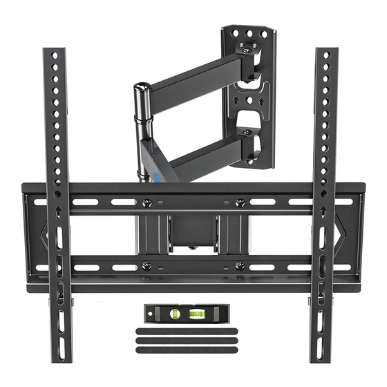
Page 3: Hardware Included
Hardware Included Brackets Arm and Wall Plate Hardware WARNING: (Wall /Product) This product contains small items that could be a choking hazard if swallowed. Before starting assembly, verify Washers Open end wrench Lag Bolts Ø8mm all parts are included and undamaged. If 5/16 x 2½... - Page 4 STEP 1-1 Select TV Screw Diameter Thread screws by hand into the threaded holes on the back of your TV to select which screw diameter fits your TV. STEP 1-2 Select TV Screw Length Too Short Too Long Correct Correct - 4 -...
- Page 5 STEP 1-3 Attach the Bracket Position your brackets over your TV hole pattern - making sure the brackets are centered and level over the TV hole pattern. Secure the brackets using your screw/washer/spacer selection: (a) for Flat Back (b) for Round Back / Extra space CAUTION: Ensure bracket is securely fastened before moving on to the next step.
- Page 6 STEP 2A Wall Plate Installation (Wood stud) 2A-1 Locate your studs. Verify and mark the center of the stud by finding the stud edges using an awl, a thin nail, or an edge-to-edge stud finder. Position the wall plate 2A-2 your desired height and line up the holes with your stud center line.
- Page 7 2A-4 Install wall plate using lag bolts and washer B . Tighten the lag bolts until they are pulled firmly against the wall plate STEP 2B Wall Plate Installation (Concrete or Brick) Position the wall plate 2B-1 at your desired height , level the wall plate and mark the polit hole loca- tions.
- Page 8 Concrete wall anchor (NOT INCLUDED) Contact us by email help@jollyholding.com to have these additional pieces shipped directly to you. Concrete Wall Anchor 4pcs Concrete Wall Install wall plate using lag bolts washer and anchor (not included). Tighten the lag bolts until they are Concrete Wall pulled firmly against the wall plate...
- Page 9 Adjustments (Tilting) Tilting angle adjustment (+5° / -10°) Pull TV to your desired angle then fasten tilting nuts with open end wrench. (Leveling) ±3° Leveling adjustment (-3°/+3°) If needed, TV can be leveled ±3 degrees via adjusting the 4 nuts with the open end wrench.
-
Page 10: Product Dimensions
Product dimensions: 5 ° 10 ° 84mm 498mm 435mm MAX:400mm MIN:75mm 435mm - 10 -...
Need help?
Do you have a question about the MU0011 and is the answer not in the manual?
Questions and answers