KROHNE 3100 C Operating Instructions Manual
Optiswitch
Hide thumbs
Also See for 3100 C:
- Operating instructions manual (32 pages) ,
- Handbook (32 pages) ,
- Technical data sheet (19 pages)
Table of Contents
Advertisement
Quick Links
Advertisement
Table of Contents

Subscribe to Our Youtube Channel
Related Manuals for KROHNE 3100 C


Summary of Contents for KROHNE 3100 C
-
Page 1: Operating Instructions
Operating Instructions OPTISWITCH 3100 C - two-wire Document ID: 29955... -
Page 2: Table Of Contents
7 Maintenance and fault rectification Maintenance ........................21 Rectify faults ........................21 Exchanging the electronics module ................22 Instrument repair ......................23 Dismount Dismounting steps......................24 Disposal ......................... 24 Supplement Technical data ........................ 25 Dimensions ........................28 OPTISWITCH 3100 C • - two-wire... -
Page 3: Optiswitch 3100 C • - Two-Wire
Supplementary documents appropriate to the ordered version come with the delivery. You can find them listed in chapter "Product descrip- tion". Instructions manuals for accessories and replacement parts Tip: To ensure reliable setup and operation of your OPTISWITCH 3100 C, we offer accessories and replacement parts. The corresponding documentations are: • Operating instructions manual "Oscillator" Editing status:2014-05-26 OPTISWITCH 3100 C • - two-wire... -
Page 4: About This Document
This arrow indicates a single action. Sequence of actions Numbers set in front indicate successive steps in a procedure. Battery disposal This symbol indicates special information about the disposal of bat- teries and accumulators. OPTISWITCH 3100 C • - two-wire... -
Page 5: For Your Safety
During work on and with the device the required personal protective equipment must always be worn. Appropriate use The OPTISWITCH 3100 C is a sensor for point level detection. You can find detailed information about the area of application in chapter "Product description". Operational reliability is ensured only if the instrument is properly used according to the specifications in the operating instructions manual as well as possible supplementary instructions. -
Page 6: Safety Label On The Instrument
CE conformity This device fulfills the legal requirements of the applicable EC guide- lines. By attaching the CE mark, we provide confirmation of success- ful testing. SIL conformity OPTISWITCH 3100 C meets the requirements to the functional safety according to IEC 61508. Further information is available in the Safety Manual "OPTISWITCH 3XXX". Safety instructions for Ex areas Please note the Ex-specific safety information for installation and op- eration in Ex areas. These safety instructions are part of the operating instructions manual and come with the Ex-approved instruments. -
Page 7: Product Description
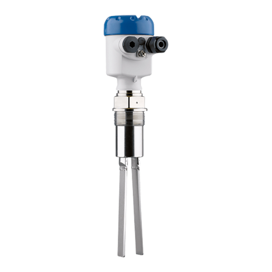
Principle of operation Application area OPTISWITCH 3100 C is a point level sensor with tuning fork for point level detection. It is designed for industrial use in all areas of process technology and is preferably used for bulk solids. -
Page 8: Operation
It also works when subjected to strong external vibrations or changing products. Solid detection in water If OPTISWITCH 3100 C was ordered for solids detection in water, the tuning fork is set to the density of water. In air or when immersed in water (density: 1 g/cm³/0.036 lbs/in), OPTISWITCH 3100 C signals "uncovered". Only when the vibrating element is also covered with... - Page 9 Not exposed to corrosive media • Protected against solar radiation • Avoiding mechanical shock and vibration • Storage and transport Storage and transport temperature see chapter "Supplement - temperature Technical data - Ambient conditions" • Relative humidity 20 … 85 % OPTISWITCH 3100 C • - two-wire...
-
Page 10: Mounting
You can find the specifications in chapter "Technical data" and on the nameplate. In general, OPTISWITCH 3100 C can be installed in any position. The Switching point instrument only has to be mounted in such a way that the vibrating element is at the height of the desired switching point. -
Page 11: Mounting Instructions
To achieve a very precise switching point, you can install OPTIS- WITCH 3100 C horizontally. However, if the switching point can have a tolerance of a few centimeters, we recommend mounting OPTIS- WITCH 3100 C approx. 20° inclined to the vessel bottom to avoid buildup. OPTISWITCH 3100 C • - two-wire... - Page 12 Fig. 4: Horizontal installation Inflowing medium If OPTISWITCH 3100 C is mounted in the filling stream, unwanted false measurement signals can be generated. For this reason, mount OPTISWITCH 3100 C at a position in the vessel where no disturbanc- es, e.g. from filling openings, agitators, etc., can occur. Product flow To make sure the tuning fork of OPTISWITCH 3100 C generates as little resistance as possible to product flow, mount the sensor so that the surfaces are parallel to the product movement.
- Page 13 Marking on top with screwed version Baffle protection against In applications such as grit chambers or settling basins for coarse falling rocks sediments, the vibrating element must be protected against damage with a suitable baffle. This baffle must be manufactured by you. > 125 mm (> 5") Fig. 7: Baffle for protection against mechanical damage OPTISWITCH 3100 C • - two-wire...
-
Page 14: Connecting To Power Supply
Proceed as follows: 1. Unscrew the housing cover 2. Loosen compression nut of the cable entry gland 3. Remove approx. 10 cm (4 in) of the cable mantle, strip approx. 1 cm (0.4 in) of insulation from the ends of the individual wires 4. Insert the cable into the sensor through the cable entry 5. Lift the opening levers of the terminals with a screwdriver (see following illustration) OPTISWITCH 3100 C • - two-wire... -
Page 15: Wiring Plan, Single Chamber Housing
The following illustrations apply to the non-Ex as well as to the Ex-d version. Housing overview Fig. 9: Material versions, single chamber housing Plastic (not with EEx d) Aluminium Stainless steel (not with EEx d) Filter element for pressure compensation (not with EEx d) OPTISWITCH 3100 C • - two-wire... - Page 16 For further information see the "Technical data" in the "Supplement". The wiring example is applicable for all suitable signal conditioning instruments. If the mode switch of OPTISWITCH 3100 C is correctly set to "max.", the control lamp on OPTISWITCH 3100 C lights. • red - with submerged vibrating element • green - with uncovered vibrating element Take note of the operating instructions manual of the signal condition- ing instrument.
-
Page 17: Setup
• Signal lamp (5) Note: As a rule, always set the mode with mode switch (2) before starting the setup of OPTISWITCH 3100 C . If the instrument is used in con- junction with a signal conditioning instrument, always set the mode switch (2) on OPTISWITCH 3100 C to max. mode. The mode is selected on the signal conditioning instrument with the mode switch. -
Page 18: Function Chart
6 Setup With the potentiometer you can adapt the switching point to the solid. Switching point adapta- tion (1) It is already preset and must only be modified in special cases. By default, the potentiometer of OPTISWITCH 3100 C is set to the right stop (> 0.02 g/cm³ or 0.0008 lbs/in³). In case of very light-weight solids, turn the potentiometer to the left stop (> 0.008 g/cm³ or 0.0003 lbs/in³). OPTISWITCH 3100 C will thus be more sensitive and can detect light-weight solids more reliably. - Page 19 The following chart provides an overview of the switching conditions depending on the adjusted mode of the signal conditioning instru- ment and the level. Note: Keep in mind that the mode switch of OPTISWITCH 3100 C must be always set to "max.". Mode on the signal Level...
- Page 20 Mode on the signal Level Signal current - Signal lamp - sen- Signal lamp - sig- conditioning in- Sensor nal conditioning strument instrument Mode B approx. 8 mA Dry run protection Green Fault message < 2.3 mA (mode A/B) flashes red OPTISWITCH 3100 C • - two-wire...
-
Page 21: Maintenance And Fault Rectification
Exchanging the electronics module tronics module instrument defective Exchange the instrument or send it in for repair Reaction after fault recti- Depending on the reason for the fault and the measures taken, the fication steps described in chapter "Set up" may have to be carried out again. OPTISWITCH 3100 C • - two-wire... -
Page 22: Exchanging The Electronics Module
9. Insert the electronics module carefully. Make sure that the plug is in the correct position. 10. Screw in and tighten the two holding screws with a screwdriver (Torx size T10 or Phillips 4) 11. Insert the wire ends into the open terminals according to the wir- ing plan OPTISWITCH 3100 C • - two-wire... -
Page 23: Instrument Repair
By doing this you help us carry out the repair quickly and without hav- ing to call back for needed information. • Print and fill out one form per instrument • Clean the instrument and pack it damage-proof • Attach the completed form and possibly also a safety data sheet to the instrument OPTISWITCH 3100 C • - two-wire... -
Page 24: Dismount
WEEE directive. Correct disposal avoids negative effects on humans and the environ- ment and ensures recycling of useful raw materials. Materials: see chapter "Technical data" If you have no way to dispose of the old instrument properly, please contact us concerning return and disposal. OPTISWITCH 3100 C • - two-wire... -
Page 25: Supplement
Ʋ American pipe thread, conical 1½ NPT (ASME B1.20.1) Instrument weight (depending on pro- 0.8 … 4 kg (0.18 … 8.82 lbs) cess fitting) Max. lateral load 600 N (135 lbf) Fig. 36: Max. lateral load alongside fork side (narrow fork side) Output variable Output Two-wire output Suitable signal conditioning instrument SU 501 Ex OPTISWITCH 3100 C • - two-wire... - Page 26 (-58°F) (122°F) (212°F) (302°F) (392°F) (482°F) -40°C (-40°F) Fig. 37: Ambient temperature - Process temperature Process temperature Ambient temperature Temperature range with temperature adapter Product density Ʋ Standard > 0.02 g/cm³ (0.0007 lbs/in³) Ʋ adjustable > 0.008 g/cm³ (0.0003 lbs/in³) Granular size max. 10 mm (0.4 in) OPTISWITCH 3100 C • - two-wire...
- Page 27 Overvoltage category Protection class Approvals Depending on the version, instruments with approvals can have different technical data. For these instruments, please note the corresponding approval documents. They are included in the scope of delivery. Depending on the version M12 x 1, according to ISO 4400, Harting, 7/8" FF. OPTISWITCH 3100 C • - two-wire...
-
Page 28: Dimensions
½ NPT ½ NPT ½ NPT Fig. 38: Housing versions Plastic housing Stainless steel housing Aluminium housing G1½ ø 43 mm (1.69") Fig. 39: OPTISWITCH 3100 C, threaded version G1½ A (DIN ISO 228/1) OPTISWITCH 3100 C • - two-wire... - Page 29 9 Supplement ø 34 mm (1.34") Fig. 40: Temperature adapter OPTISWITCH 3100 C • - two-wire...
- Page 30 Notes OPTISWITCH 3100 C • - two-wire...
- Page 31 Notes OPTISWITCH 3100 C • - two-wire...
- Page 32 Subject to change without notice 29955-EN-140630...
Need help?
Do you have a question about the 3100 C and is the answer not in the manual?
Questions and answers