Table of Contents
Advertisement
Quick Links
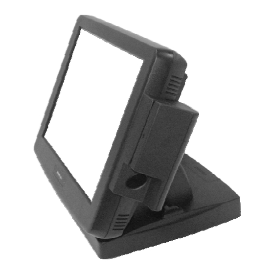
KS - 6215 PLUS
Fan Free Touch Terminal
w/ Slim Base
User's Manual
Rev.: Original
FCC Notes:
This equipment generates, uses, and can radiate radio frequency energy and, if not
installed and used in accordance with the instructions manual, may cause interference
to radio communications. It has been tested and found to comply with limits for a Class
A digital device pursuant to subpart J of Part 15 of FCC Rules, which are designed to
provide reasonable protection against interference when operated in a commercial
environment. Operation of this equipment in a residential area is likely to cause
interference in which case the user at his own expense will be required to take whatever
measures to correct the interference.
Warranty Limits:
Warranty terminates automatically when any person other than the authorized
technicians opens the machine. The user should consult his/her dealer for the problem
happened. Warranty voids if the user does not follow the instructions in application of
this merchandise. The manufacturer is by no means responsible for any damage or
hazard caused by improper application.
About This Manual:
Posiflex has made every effort for the accuracy of the content in this manual. However,
Posiflex Technologies, Inc. will assume no liability for any technical inaccuracies or
editorial or other errors or omissions contained herein, nor for direct, indirect,
incidental, consequential or otherwise damages, including without limitation loss of
data or profits, resulting from the furnishing, performance, or use of this material.
This information is provided "as is" and Posiflex Technologies, Inc. expressly
disclaims any warranties, expressed, implied or statutory, including without limitation
implied warranties of merchantability or fitness for particular purpose, good title and
against infringement.
The information in this manual contains only essential hardware concerns for general
user and is subject to change without notice. Posiflex Technologies, Inc. reserves the
right to alter product designs, layouts or drivers without notification. The system
integrator shall provide applicative notices and arrangement for special options utilizing
this product. The user may find the most up to date information of the hardware from:
http://www.posiflex.com or http://www.posiflex.com.tw or http://www.posiflexusa.com
All data should be backed-up prior to the installation of any drive unit or storage
peripheral. Posiflex will not be responsible for any loss of data resulting from the use,
disuse or misuse of this or any other Posiflex product.
All rights are strictly reserved. No part of this documentation may be reproduced,
stored in a retrieval system, or transmitted in any form or by any means, electronic,
mechanical, photocopying, or otherwise, without prior express written consent from
Posiflex Technologies, Inc. the publisher of this documentation.
© Copyright Posiflex Technologies, Inc. 2008
All brand and product names and trademarks are the property of their respective holders.
Part 1
P/N: 16580900010
Advertisement
Table of Contents

Related Manuals for POSIFLEX KS-6215 PLUS


Summary of Contents for POSIFLEX KS-6215 PLUS
- Page 1 About This Manual: Posiflex has made every effort for the accuracy of the content in this manual. However, Posiflex Technologies, Inc. will assume no liability for any technical inaccuracies or editorial or other errors or omissions contained herein, nor for direct, indirect, incidental, consequential or otherwise damages, including without limitation loss of data or profits, resulting from the furnishing, performance, or use of this material.
- Page 2 ALERT TO OUR HONORABLE CUSTOMERS: l Please always read thoroughly all the instructions and documents delivered with the product before you do anything about it. Don’t take any premature action before you have a full understanding of the consequences. l This product contains inside a Lithium battery. Please always follow local environmental protection laws / regulations for disposal of used batteries and always replace only with battery of same type.
-
Page 3: Product Pictures
INTRODUCTION PRODUCT PICTURES Front Views Gen 4 base Gen 5 base Gen 4 base Gen 5 base Side Views Gen 4 base Gen 5 base Gen 4 base Inside touch open door Gen 5 base Part 3... -
Page 4: Parts Identification
Rear Views Gen 4 base Gen 5 base Bottom Views Gen 4 base Gen 5 base PARTS IDENTIFICATION Main unit Touch panel / LCD panel Power indicator Gen 4 slim base stand Gen 5 slim base stand Optional side mount kit e.g. SD-400Z Cable cover Removal hollow in cable cover Lock / release lever for tilt angle adjust... -
Page 5: Product Features
20. 2.5” HDD bracket cover in Gen 4 base 21. Rubber foot 22. Gen 4 base 2.5” HDD bracket fixing screw 23. Base mount device cable groove 24. Cable holder 25. Cable passage in bottom plate 26. Rubber foot with bottom plate fixing screw PRODUCT FEATURES Standard Features: CPU: VIA C7 1.5 GHz... - Page 6 Touch control functions: left/right button, double click, drag & draw Dual display support (per OS capability) VGA memory size shared from system memory (16 ~ 64 MB) Support high performance DDR2 SO-DIMM SDRAM with maximum memory size 1GB in one module Integrated structure for side mount upgrade kit like SD-400Z with software programmable MSR parameters for WEPOS or Win XP pro Built-in internal speaker with 2 W audio amplifier...
-
Page 7: Opening Cable Cover
INSTALLATION GUIDES CAUTION: Before any installation or cable connection to the set, please always make certain that the system is turned off and the external power source to the set is removed to prevent electric hazard! Never touch any metal pin in the connectors or circuits to avoid high voltage hazard or electrostatic discharge damage unless the operator is well grounded. -
Page 8: Separating Main Unit
SEPARATING MAIN UNIT In order to settle the touch terminal properly in a point of sale system, all the cable connections have to be routed through its base, either slim or universal. Therefore, please observe the procedures from A to C below to separate the main unit from both slim and universal base stand assembly after all cables in cable cover disconnected. -
Page 9: Base Mount Upgrade Kit
1. 2 Cable Exit 2. Cable Exit 3. Rear Connect Cover Hook Plate 4. Cable Passage To Main Unit For Desktop Mount Application 5. Option HDD Bracket Fixing Screw 6. Option HDD Bracket 7. Option HDD Conversion Board Inside Gen 5 base 8. - Page 10 12” 2 LCD Panel Or Customer Display Fit the joint base of PD-306 or PD-2501 or PD- 2602 or LM-6101 to the rear connect cover opening. Please route interface cable through the normal cable exit (under the joint base) as in the 2 pictures.
-
Page 11: Preparing The Main Unit
Please note that only those qualified technicians may adjust in the service window with information from Posiflex and the contents in the service window may change without notice as time develops. -
Page 12: Rear Top Mount Upgrade Kit
REAR TOP MOUNT UPGRADE KIT Please apply carefully the 2 small fixation shoulder screws that come along with PD-310 or PD-2604 to the back of KS series at the screw hole triangle marked in the 2 upper right pictures. However please do not screw them to the bottom but at a position that is about 1 turn loose from the bottom. -
Page 13: Wall Mounting
press down the lock/release button on back of the stand at the time lifting the main unit. For desk top/counter application, the total dimension of Gen 4 slim base KS-6215PLUS occupies a space of 378 mm wide, 297 to 308 mm deep and 283 to 359 mm high per main unit tilt angle. -
Page 14: Operating System Recovery
For KS systems preloaded with Windows XP Pro or WEPOS on HDD, Posiflex provides recovery DVD delivered with the touch terminal for the preloaded operating system. The System Integrator shall take care of software restoration after OS recovered. A Posiflex supplied USB interface COMBO drive will be required for such action. -
Page 15: Application Environment
USING THE TOUCH TERMINAL APPLICATION ENVIRONMENT It is very important that you check the following operational guidelines: Ventilation This terminal must NOT be operated in an environment with restricted ventilation. There must be at least 25 mm air clearance around any top or side ventilation holes with a free flow of air around the unit at ALL times for the installation. -
Page 16: Display Issues
Hardware Power Switch The power switch located in the touch open cover of the main unit is a tactile pushbutton switch. This switch controls the power on/off of the system. This switch turns the system on when pushed only when external power is present. -
Page 17: Customer Display
LM-6101, have a qualified technician to set an internal jumper in KS main unit to supply the required power through the VGA connector according to Posiflex technical information. Do not connect other monitor to this port before the power in this port is disabled. -
Page 18: Touch Panel
CF CARD If the CF card reader is installed and the CF card is used for system data storage device, it is recognized by the system as the IDE channel 0 Master device. Please note that usual utilities such as FDISK.EXE or FORMAT.COM must never be used on CF card or permanent damage can occur. - Page 19 Posiflex USB Touch Manager A program named “Posiflex USB Touch Manager” and a right-click sticky button tool in the program group “Posiflex USB Touch Tools” is installed in the preloaded Windows system with a USB interface touch panel controller. This program can also be obtained by download from the POSIFLEX web site.
- Page 20 T31454 警告使用者 這是甲類的資訊產品,在居住的環 境 中 使 用 時 , 可 能 會 造 成 射 頻 干 擾,在這種情況下,使用者會被要 求採取某些適當的對策。 警告 Part 20 本電池如果更換不正確會有爆炸的危險 請依製造商說明書處理用過之電池...
Need help?
Do you have a question about the KS-6215 PLUS and is the answer not in the manual?
Questions and answers