Table of Contents
Advertisement
Quick Links
QUESTIONS?
Ask the experts at POSMicro.com.
1.800.241.6264
Live Chat Now
support@POSMicro.com
Monday - Friday 6 AM to 5 PM Pacific Time
1.800.241.6264
Posiflex KS7300
Manual
More information available at
BULk DISCOUNTS
FREE SHIPPING*
*Free ground shipping to the continental USa on orders over $100.
For Help Call
POSMicro.com
SE HaBLa
ESpañOL
Advertisement
Table of Contents

Subscribe to Our Youtube Channel
Related Manuals for POSIFLEX KS7300 Series


Summary of Contents for POSIFLEX KS7300 Series
- Page 1 For Help Call 1.800.241.6264 Posiflex KS7300 Manual More information available at POSMicro.com QUESTIONS? BULk DISCOUNTS SE HaBLa Ask the experts at POSMicro.com. ESpañOL FREE SHIPPING* 1.800.241.6264 Live Chat Now support@POSMicro.com Monday - Friday 6 AM to 5 PM Pacific Time...
- Page 2 About This Manual: Posiflex has made every effort for the accuracy of the content in this manual. However, Posiflex will assume no liability for any technical inaccuracies or editorial or other errors or omissions contained herein, nor for direct, indirect, incidental, consequential or otherwise damages, including without limitation loss of data or profits, resulting from the furnishing, performance, or use of this material.
- Page 3 ALERT TO OUR HONORABLE CUSTOMERS: l Please always read thoroughly all the instructions and documents delivered with the product before you do anything about it. Don’t take any premature action before you have a full understanding of the consequences. l This product contains inside a Lithium battery and maybe also a sealed type Lead acid battery if the UPS battery option is ordered.
-
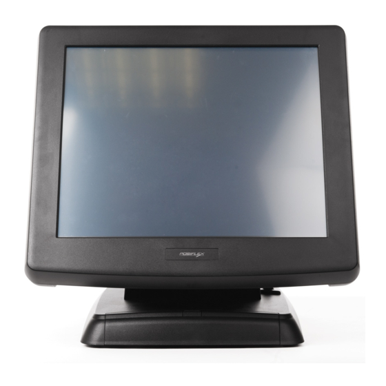
Page 4: Product Pictures
INTRODUCTION PRODUCT PICTURES Front Views w/ Gen 5 base w/ Gen 6 base w/ Gen 5 base w/ Gen 6 base Side Views w/ Gen 5 base w/ Gen 5 base w/ Gen 6 base w/ Gen 5 base w/ Gen 6 base Inside the touch open cover Rear Views w/ Gen 5 base... -
Page 5: Parts Identification
Bottom Views Gen 5 base Gen 6 base PARTS IDENTIFICATION 1. Main unit 16. Optional top mount upgrade kit 2. Optional base mount kit e.g. e.g. PD-310 or PD-2604 PD-306 for Gen 5 Slim base 17. Power switch model 18. Brightness adjust push button 3. -
Page 6: Product Features
PRODUCT FEATURES Standard Features: Applicable CPU: 1. for KS-6615 only: Intel Celeron M 1.0 GHz 2. for KS-6615 / 6617: Interl Celeron M 1.5 GHz 3. for KS-7315 / 7317: Intel Celeron M 1.86 GHz or Core Duo 2.0 GHz or Core 2 Duo 2.16 GHz Fan free structure with Aluminum main unit for harsh environment Data storage device: SATA HDD 2.5”... - Page 7 11. one UPS battery connector Touch control functions: left/right button, double click, drag & draw Dual display support (per OS capability) Dynamic video memory (max. 128 MB for KS-6615 / KS-6617, max. 224 MB for KS-7315 / KS-7317) Support high performance DDR2 DRAM with maximum memory size 1GB for KS-6615/6617 and 2GB for KS-7315/7317 in one module Integrated structure for side mount upgrade kit like SD-400W with software programmable MSR parameters for Win XP or WEPOS...
-
Page 8: Opening Cable Cover
INSTALLATION GUIDES CAUTION: Before any installation or cable connection to the set, please always make certain that the system is turned off and the external power source to the set is removed to prevent electric hazard! Never touch any metal pin in the connectors or circuits to avoid high voltage hazard or electrostatic discharge damage unless the operator is well grounded. -
Page 9: Separating Main Unit
when disconnecting any connector. Failure to do this could damage the cable and jack that is considered as an artificial destruction. Damages due to incorrect disconnection operation are not covered by product warranty! SEPARATING MAIN UNIT In order to settle the touch terminal properly in a point of sale system, all the cable connections have to be routed through its base. - Page 10 battery cable. The UPS battery will be held in place when the bottom plate is screwed back. As for gen 6 super slim base model, please remove the UPS battery bracket on bottom of the stand assembly instead of the bottom plate as in the right picture. Please pay particular attention to the environment requirements for UPS battery in next Gen 6 base...
-
Page 11: Preparing The Main Unit
ROUTING THE CABLES Gen 5 base Gen 5 base Gen 5 base The designed cable routing for all external cable connections referring to the pictures above is to have all the cables coming from outside into the cable exit (position A) at bottom side of gen 5 slim base and to be regulated into the two cable holders (B) then enter the base through the passage (C). - Page 12 Please note that only those qualified technicians Jumpers adjust service window with information from Posiflex and the contents in the Service Window service window may change Lock Screw without notice as time develops. SIDE MOUNT UPGRADE KIT (OPTION) Remove the 2 screws circled in last picture above to remove the cover for side mount upgrade kit.
-
Page 13: Desktop Mounting
The RJ11 connector in main connection area of a KS system can be used for controlling most of the common cash drawers available on the market. However, it is most recommended that the Posiflex CR-2000 or CR-2200 or CR-3100 or CR-3200 or CR-4000 or CR-4100 or CR-4210 or CR-6210 be used for best compliance. -
Page 14: Wall Mounting
Then slide the main unit down to move the pegs into the lower slot part of the holes till it clicks. Note that all the cables come out of the stand from the lower edge and won’t get trapped by this mounting operation. If later on you want to remove the main unit from the stand, you’ll have to press down the lock/release button on back of the stand at the time lifting the main unit. -
Page 15: Connecting Cables
Align the four matching pegs on the back of the main unit as circled in the below left picture with the four matching holes in the wall mount brackets as also marked in circles in the top pictures and allow the main unit to slide down the winding grooves in the wall mount backpack. -
Page 16: Operating System Installation
For KS systems preloaded with Windows XP Pro or WEPOS on HDD, Posiflex provides recovery CD or DVD delivered with the touch terminal for the preloaded operating system. The System Integrator shall take care of software restoration after OS recovered. A Posiflex supplied USB interface CDROM drive will be required for such action. - Page 17 be powered off for more than few days, please always disconnect the battery from the system. Reconnect it and turn on the system to recharge the battery for 1 ~ 2 hours every 3 months for temperature lower than 30°C. Recharge for 1 ~ 2 hours every month for temperature over 30°C.
- Page 18 POWER ON/OFF & BRIGHTNESS CONTROL Touch Open Cover A gentle tap on the touch w/ Gen 5 base w/ Gen 6 base open cover at left side of the main unit will open the cover and show the power switch, brightness adjust push button switches and a double deck USB connector.
-
Page 19: Customer Display
In preloaded Windows, “Posiflex Power Switch Manager” in “Posiflex Tools” in the Program Files helps managing these functions. Software Support Features The KS series provides a software power off command for application program maneuvers. -
Page 20: Display Issues
Posiflex monitor, use the DC adaptor to connect into the monitor (for TM-4115 / TM-7112) or its VGA cable (for LM-6212) or use Posiflex VGA + power cable and set an internal jumper in KS main unit to supply the required power through the VGA connector (for LM-6212). - Page 21 Posiflex USB Touch Manager A program named “Posiflex USB Touch Manager” and a right-click sticky button tool in the program group “Posiflex USB Touch Tools” is installed in the preloaded Windows system with a USB interface touch panel controller. This program can also be obtained by download from the POSIFLEX web site.
Need help?
Do you have a question about the KS7300 Series and is the answer not in the manual?
Questions and answers