Table of Contents
Advertisement
Quick Links
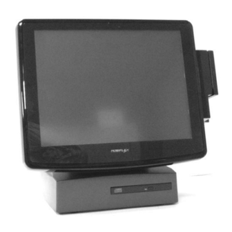
KS-6215I / KS-6217
MANUFACTURED BY:
ISO-9001
AN
6,WU-CHUAN RD.,HSIN-CHUANG TEL: 886-2-2991599 (REP.) FAX: 886-2-2991819, 2991808
(WU-KU INDUSTRIAL ZONE)
TAIPEI HSIEN, TAIWAN
Jiva KS-6215 /
SERIES
TECHNICAL MANUAL
Rev. : Preliminary
POSIFLEX TECHNOLOGIES, INC.
ISO-14001
AND
http://www.posiflex.com
http://www.posiflexusa.com
CERTIFIED MANUFACTURER
http://www.posiflex.com.tw
EMAIL: posiflex@posiflex.com.tw
Advertisement
Table of Contents

Related Manuals for POSIFLEX Jiva KS-6215 Series


Summary of Contents for POSIFLEX Jiva KS-6215 Series
- Page 1 Jiva KS-6215 / KS-6215I / KS-6217 SERIES TECHNICAL MANUAL Rev. : Preliminary POSIFLEX TECHNOLOGIES, INC. MANUFACTURED BY: ISO-9001 ISO-14001 CERTIFIED MANUFACTURER 6,WU-CHUAN RD.,HSIN-CHUANG TEL: 886-2-2991599 (REP.) FAX: 886-2-2991819, 2991808 (WU-KU INDUSTRIAL ZONE) http://www.posiflex.com http://www.posiflex.com.tw TAIPEI HSIEN, TAIWAN http://www.posiflexusa.com EMAIL: posiflex@posiflex.com.tw...
- Page 2 All rights are strictly reserved. No part of this documentation may be reproduced, stored in a retrieval system, or transmitted in any form or by any means, electronic, mechanical, photocopying, or otherwise, without the prior written consent of Posiflex Technologies, Inc. the publisher of this documentation.
-
Page 3: Table Of Contents
TABLE OF CONTENTS OVERVIEW ..........1 - 1 SCOPE . - Page 4 2.5” HDD IN MAIN UNIT ......2 - 8 SIDE MOUNT UPGRADE KIT KP3 ....2 - 8 .
- Page 5 SYSTEM DEFINITIONS ....... . . 4 - 1 BLOCK DIAGRAM ........4 - 1 12 V DC IN CONNECTOR .
- Page 6 POSIFLEX TOOLS ........5 - 9...
- Page 7 ....5 - 17 USB TOUCH RIGHT BUTTON TOOL RS232 TOUCH DRIVER ....... 5 - 18 SOFTWARE COMMAND INDEX .
- Page 8 SERVICE AND SPARE PARTS ......7 - 1 SERVICE GUIDE ........7 - 1 SIDE MOUNT UPGRADE KIT .
-
Page 9: Overview
OVERVIEW SCOPE The Jiva KS-6215 / KS-6217 series is a series of fully integrated PC based Point-Of-Sale terminals. This series provides excellent performance for Point-Of-Sale, Hospitality and Kiosk systems with a VIA CPU of C7 1G or above in nanoBGA2 package inside an Aluminum alloy die cast enclosure without any exhaust fan. - Page 10 l Extra long life resistive type touch panel that endures 35 million touches at same spot or optional InfraRed type touch sensor giving maximum clarity l Spill proof water resistant structure allowing easy cleaning l Highly glossy anti-scratch top surface (2H) l Easy maintenance construction l Various I/O ports supported, including:...
-
Page 11: Optional Items
Preload Win XP Pro, WEPOS or WinCE g) UPS battery h) USB interface external slim type CD-ROM/CD-RW/DVD-ROM drive Wireless LAN adaptor in USB interface Wireless Dongle for Posiflex wireless POS printers k) Posiflex POS printers KS-6215 / KS-6215I / KS-6217 series Technical Manual 1 - 3... - Page 12 RJ45 to DB9 conversion cable m) Wall mount kit WB-6000, WB-6300, WB-6600, WB-6800 etc. KS-6215 / KS-6215I / KS-6217 series Technical Manual 1 - 4...
-
Page 13: General Specifications
GENERAL SPECIFICATION SYSTEM l CPU: VIA C7 1G or above l DDR2 533 SODIMM : 256 MB (expandable to 1GB) l Built-in 3.5”SATA interface HDD 80 GB or above in base POWER SOURCE DC power adaptor: Item Specification Voltage range of adaptor input 100 ~ 240 V AC Load limit of adaptor input 2.5 A max. -
Page 14: Ups Support (Battery Option)
UPS SUPPORT (battery option) l Supports system operation for up to 30 min. depending on loading condition l LED panel turns on green when adaptor power stand-by l LED panel flashes in blue and system beeps when UPS battery starts working and discharging, and LED panel flashes in green when UPS near to end l Working on UPS battery status can be detected through COM1 status port... -
Page 15: Hdd In Base
l 1 x UPS connector for 2.3AH/12V or above Lead Acid battery HDD IN BASE l One 80 GB or above operating up to ultra SATA2 TOUCH PANEL l Extremely endurable life survives minimum 35,000,000 touches at same spot l Touch control interface: USB (optional RS232 interface for IR type) l Sensor type: resistive (InfraRed type for KS-6215I) l Resolution: 1024 x 1024 for resistive type touch panel l Calibration: initial calibration at setup only, no re-calibration required for... - Page 16 KS-6215 / KS-6215I / KS-6217 series Technical Manual 2 - 4...
-
Page 17: Led Module Color
LED MODULE COLOR l Type: blue/green dual color (blue for power on; green for stand by) l Indication coverage: system ON/OFF status, external power status, UPS battery monitoring AUDIO AMPLIFIER l Input/Output connectors exist on optional side mount upgrade kit like KP- 300, SD-400, SD-600 only l 30 db gain for microphone input l Output audio power 2.0 W (in mono signal to internal speaker in back... -
Page 18: Environmental
LCD @ 72.5°: 410 mm (W) x 342 mm (D) x 290 mm (H) or 16.1” x 13.5” x 11.4” PACKING: 558 mm (W) x 488 mm (D) x 370 mm (H) or 22.0” x 19.2” x 14.6” l 17” UNIVERSAL BASE MODEL DIMENSIONS: LCD @ 15°: 410 mm (W) x 304 mm (D) x 430 mm (H) or 16.1”... -
Page 19: Accessories
ACCESSORIES l User’s manual: 1 copy l Power adapter 12 V DC 6.6 A plus power cord l Product Information CD or Recovery CD of preloaded OS l DB9 / RJ45 conversion cable: 4 pcs COMPLIANCE APPROVALS l Whole system meet CE, FCC class A standard (meet IEC61000-4-2/-3/-4/-5/-6/-8/-11) l Power supply is UL, VDE approved l RoHS... -
Page 20: Options
OPTIONS SECOND DISPLAY ON REAR BASE Model Number LM6101 LM6301 COLOR TFT 12.1” COLOR TFT 15.0” Display Type 245.8 X 184.3 mm 304.1 X 228.1 mm View area Interface 180 cd/m 250 cd/m Luminance CCFL x 1 CCFL x 2 Backlight 350 : 1 500 : 1... -
Page 21: Dram Expansion
157.05 x Display area (mm x mm) 193 x 39 142.8 x 20.64 22.86 260 x 65 x 197 x 56 x Display head size (mm) 218 x 35 x 89 Pole mount Mounting method Pole mount on base Base mount on base Pole height (mm) N. -
Page 22: Programmable Keypad
l Functions include: programmable keypad with 36 keys plus 6- position electronic key-lock, MSR, smart card reader, Mic. in & audio output connectors PROGRAMMABLE KEYPAD 1 electronic 6-position control key to lock up or determine among 5 different pages of programmable keys 16 key numeric keypad with a double sized “Enter”... -
Page 23: Magnetic Stripe Reader
MAGNETIC STRIPE READER ISO 2 tracks ((track 1 + track 2) or (track 2 + track 3)) or ISO 3 tracks (track 1 + track 2 + track 3) or JIS I/II Characteristic parameters of ISO readers can be set via software AAMVA/CA DMV format supported in ISO 3 tracks model OPTICAL FINGER PRINT SENSOR Detection area : 14.6 x 18.1 mm (nominal at center) -
Page 24: Audio Port
or ISO 3 tracks (track 1 + track 2 + track 3) or JIS I/II Characteristic parameters of ISO readers can be set via software AAMVA/CA DMV format supported in ISO 3 tracks model AUDIO PORT 3.5 Ø mono jack for Mic. In 3.5 Ø... -
Page 25: External Cd Rom Drive
EXTERNAL CD ROM DRIVE l 24 x speed l USB interface l Slim type WALL MOUNT KITS l Devices installable in backpack of each kit type are as below: KIT NAME DEVICES N. A. WB-6000 WB-6300 2.5” HDD, UPS battery 3.5”... -
Page 26: Pp-7000Ii
PP-7000U USB interface All other features same as PP7000II PP-7700 1. Posiflex wireless connection 2. Requires a dongle DG2000 connected on COM port of host to control 3. All other features same as PP7000II KS-6215 / KS-6215I / KS-6217 series Technical Manual 2 - 14... -
Page 27: Reliability Specification
RELIABILITY SPECIFICATION l POWER ADAPTOR MTBF: 50,000 HRS l TOUCH PANEL LIFE EXPECTANCY (TOUCHES AT SAME SPOT): IR TYPE: 50,000,000 UP RESISTIVE TYPE: 35,000,000 UP l LCD PANEL LIFE EXPECTANCY: 40,000 HRS FOR TFT l HDD MTBF: 50,000 HRS DISPLAY LCD BACK LIGHT LIFE EXPECTANCY: LM6101: 10,000 HRS LM6301: 30,000 HRS l CUSTOMER DISPLAY LIFE EXPECTANCY:... - Page 28 l POWER SWITCH LIFE EXPECTANCY: 50,000 STROKES l MOTHER BOARD MTBF: 50,000 HOURS l EXTERNAL FDD MTBF: 80,000 HRS KS-6215 / KS-6215I / KS-6217 series Technical Manual 3 - 2...
-
Page 29: System Definitions
SYSTEM DEFINITIONS BLOCK DIAGRAM LPC I/O RS232 DDR2 533 COM4 17” LCD MNGR F81216D Device (+5V) SODIMM connector Inverter RS232 15” LCD RS232 IR COM3 connector Device Battery Circuit connector (+5V) Touch Touch VIA C7 1G controller controller LVDS Transmitter nanoBGA2 12 V DC PSU Circuit... -
Page 30: 12 V Dc In Connector
12 V DC IN CONNECTOR PIN ASSIGNMENT OF 4 PIN PLUG: PIN # DEFINITION +12 V +12 V CASE CASE CHASSIS GND UPS BATTERY CONNECTOR PIN ASSIGNMENT OF 4 PIN SOCKET: PIN # DEFINITION +12 V +12 V PIN 1 LAN PORT PIN ASSIGNMENT OF 8 PIN TELEPHONE JACK: PIN # DEFINITION... -
Page 31: Vga Connector
VGA CONNECTOR l This port is a standard 3 x 5 D-sub VGA connector PIN # DEFINITION PIN # DEFINITION PIN # DEFINITION NCID0 GREEN DDC_DATAID1 BLUE HSYNC NCID2 NC/+12VKEY VSYNC DDC_CLKID3 SERIAL PORT COM1 PIN ASSIGNMENT OF DB9M – 10 p RJ45 CONVERSION CABLE: DB9M RJ45 PIN # PIN # DEFINITION ALTERNATIVE DEFAULT SETTING BATTWK... -
Page 32: Serial Port Com2/3/4
“COM1 APPLICATION COMMENT” in same chapter for remarks on this port. • +5 V DC supply is UPS supported. • Jumper selection: please refer to the description in Hardware details of this manual. SERIAL PORT COM2/3/4 PIN ASSIGNMENT OF 9 PIN D CONNECTOR OF CONVERSION CABLE: PIN # DEFINITION ALTERNATIVE DEFAULT SETTING +5 VDC •... -
Page 33: Parallel Port Lpt1
PARALLEL PORT LPT1 PIN ASSIGNMENT OF 25 PIN D SUB FEMALE CONNECTOR: PIN # SPP MODE EPP MODE ECP MODE - STROBE -WRITE -STROBE - ACK INTR -ACK BUSY -WAIT BUSY, PeriphAck Perror, -AckReverse SLCT SLCT - AUTO FEED -Datastb -AutoFeed, HostAck - ERROR -Fault, -PeriphRequest... -
Page 34: Ps/2 Keyboard Connector
PS/2 KEYBOARD CONNECTOR PIN ASSIGNMENT OF 6 PIN MINI-DIN FEMALE CONNECTOR: PIN # DEFINITION KBDAT KBCLK SATA CONNECTOR l This connector is a double deck SATA connector PIN ASSIGNMENT OF EACH 7 PIN CONTACTS: PIN # DEFINITION PIN 1 PIN 1 HDD POWER CONNECTOR l This connector is a small 4 pin connector with housing PIN ASSIGNMENT OF 4 PIN CONTACTS:... -
Page 35: Audio Out (On Side Mount Kit Only)
AUDIO OUT (on side mount kit only) PIN ASSIGNMENT OF 3.5 Ø STEREO JACK: CONTACT ON PLUG: DEFINITION: RING OUTER MIC. IN (on side mount kit only) PIN ASSIGNMENT OF 3.5 Ø MONO JACK: CONTACT ON PLUG: DEFINITION: OUTER KS-6215 / KS-6215I / KS-6217 series Technical Manual 4 - 7... -
Page 37: Application Guides
APPLICATION GUIDES POWER SUPPLY TO I/O PORTS On the solder side of the main board, jumpers on JP11 and JP20 in service window area determine the +5V DC supplies to the devices connected to COM1/COM2 and COM3/COM4 separately. The jumper on JP12 determines +12V DC supply to VGA port. -
Page 38: Software System Backup
SOFTWARE SYSTEM BACKUP When the system integrator purchases the POS system with preloaded OS from Posiflex, he gets a bonus support of system protection function. In the OS boot process, there are few seconds of system protection function entry screen. Pressing the three key combination of “Ctrl”... -
Page 39: Customer Display
CUSTOMER DISPLAY The RS232 model rear base mount customer display PD2501 or PD2602 or PD305 upgrade kit can be connected to any available COM port with an internally supplied power from the Jiva KS series set per instruction in Hardware Detail. The USB model PD-2602 can be connected to any available USB port with an internally supplied power from the KS-62 series. -
Page 40: Software Switch Off
This function can also be achieved by use of the Posiflex Power Switch Terminal Manager. -
Page 41: Ups Battery
switch command. This enhanced forced power off requires the user to keep the switch pressed for a longer period between 10 to 20 seconds to function. In case the system halt situation is so serious that some hardware/firmware registrations are already confused, this above mentioned forced power off could though very unlikely still fail. -
Page 42: Ups Battery Health Check
UPS BATTERY HEALTH CHECK The UPS battery health check watchdog function is introduced in the Posiflex Power Switch Manager utility version 1.03 onwards. This function helps checking the UPS battery condition and automatically popping up warning message window to remind the user of a possibly failed battery so that the user won’t have to bother... -
Page 43: Automatic Power On Control
query command is received. It is advisable to take a check on the response between 1 to 10 seconds after sending the query command and to send the other query command only after first response checked to avoid any possible ambiguity. In this product, when the system is working on UPS battery power, the status is indicated by LED and is detectable by software. -
Page 44: Lan Wake Up
LAN. Both machines should be using same brand of LAN chip. First the MAC address of the target machine should be checked. Please obtain the file “RSET8139.EXE” from Posiflex Product Information CD in subfolders like \Drivers\KS631X\LAN_621 and execute this file on the target machine. Select the item “View Current Configuration”... -
Page 45: Posiflex Tools
(SLE4418/28), SDA/I2C, 4403, 4433, 4404, 896 etc. It communicates with the system as USB 2.0 full speed device. POSIFLEX TOOLS In the preinstalled OS there will be a program group named “POSIFLEX Tools” for specific Posiflex device(s) installed. POSIFLEX POWER SWITCH MANAGER... -
Page 46: Ups Setting
USB MSR Manager. The screen shot of the program is similar to the top picture at right. The program will be in “Posiflex Tools” and in “StartUp” there will be KS-6215 / KS-6215I / KS-6217 series Technical Manual 5 - 10... -
Page 47: Use Alt-Num Emulation
USE ALT-NUM EMULATION This function is required for language systems using a different keyboard layout of the alphabetical part from the US keyboard when track 1 of the USBMSR is enabled. This function will have no influence if the MSR uses only track 2 and/or track 3. The reason is that the data of the MSR are sent to the host as if they were keyed in from a keyboard. -
Page 48: Msr Track 1 Leading Code
will always send a “CR” (carriage return) signal to end of each track data for separation if this item is unchecked. MSR TRACK 1 LEADING CODE MSR TRACK 2 LEADING CODE MSR TRACK 3 LEADING CODE MSR ENDING CODE Once the codes for the sentinels of each tracks are defined to be sent to the system, the leading codes for each start sentinels and the ending code for the common end sentinel can be selected from a table of displayable characters with ASCII code from 20h to 7Eh. -
Page 49: Additional Cr
KP-300 under Windows environment. \Drivers\KP\uKBW.xxx in Posiflex product information CD is the subfolder for executing the “SETUP.EXE” to install this utility. There will be a warning screen before the screen shot similar to the picture at right to ask the user not to disturb the keyboard initialization when this utility is engaged. -
Page 50: The Command Menu
The “Edit” menu helps the editing operation like copy, paste or clear the programmed content of a programmable key. Please ignore any gray command relating to “Page” that is applicable only to other models of Posiflex programmable keyboard and remains here only for consistency consideration. Same comment applies to the gray “View”... -
Page 51: The Answer Back Codes
Most items in this utility should be easily understandable to average user. Followings are just some reminders on some items. Calibrate – This button engages the “Posiflex USB Touch Calibrator”. KS-6215 / KS-6215I / KS-6217 series Technical Manual 5 - 15... - Page 52 Edge Acceleration – This function engages the “Posiflex USB Touch Edge Acceleration Tool” and helps to find the hidden taskbar or thin scroll bar through touch. Hide Cursor / Show Cursor – This button hides or shows the mouse cursor on screen display. Please never hide cursor before the touch is enabled and calibrated.
-
Page 53: Usb Touch Calibrator
USB TOUCH CALIBRATOR This program helps re-calibrating the touch position with the USB mouse emulation. Please touch the 3 or 9 calibration boxes and a confirmation box that appear sequentially. USB TOUCH EDGE ACCELERATION TOOL This program helps to find the hidden taskbar or thin scroll bar through touch. -
Page 54: Rs232 Touch Driver
Please find the subfolder \Drivers\KS631X\TOUCH\IR in the Posiflex Product Information CD and study the “readme” file before executing the “setup” program should there be any need for a driver re-installation. Make sure you select “COM2”... - Page 55 2 different spots. The port selection for “Touchscreen on:” must be set to “COM5” for the touch panel over the LCD panel in this product series. In case a Posiflex touch monitor is connected to the VGA port for 2 display, the touch function of the second display monitor has to be connected to one of the ports from COM2 to COM4.
-
Page 56: Software Command Index
SOFTWARE COMMAND INDEX Following table is a collection of software command applicable to the Jiva KS series for a quick look up. The page number listed could deviate from the display of this file if different viewer is utilized. Usage of the Command Page Chapter Section / Subsection Power... -
Page 57: Hardware Details
HARDWARE DETAILS MAIN BOARD (KS-6215) COMPONENT SIDE Notation Remarks: JP14 1. A small black block JP19 or a small number “1” in the drawing for a jumper or an IC is BAT1 used to indicate the JP25 position of pin number CN23 LCD1 2. -
Page 58: Solder Side
SOLDER SIDE JP21 JP11 JP12 JP13 SODIMM1 JP10 JP17 JP20 Service window details The orientation of JP13 above is for rev. C only. In rev. D it is as below: JP13 Notation Remarks: 1. A small black block or a small number “1” in the drawing for a jumper or an IC is used to indicate the position of pin number 1. -
Page 59: Jumpers And Connectors
JUMPERS AND CONNECTORS ON COMPONENT SIDE Position Part Spec Usage BAT1 Round socket CMOS battery socket BAT2 CONN 1x4 UPS battery connector Buzzer System buzzer HDR 1x4 rt w/H HDD power connector 4 pin Jack Power connector HDR 1x4 mini Reserved (COM1 data) CN11... -
Page 60: On Solder Side
JP14 HDR 2x5 uDOC connector JP17 HDR 1x3 Reserved JP19 HDR 1x5 uDOC module hold JP22 HDR 1x3 Panel power select JP23 HDR 2x2 To be deleted Audio Amplifier pass JP24 HDR 2x2 Reserved 2.5” HDD master/slave JP25 HDR 2x4 Reserved RS232 touch controller support PS2 LAN1... -
Page 61: Jumper Settings
JUMPER SETTINGS The “«” marks in the following tables denote the factory default settings. CMOS DATA CONTROL STATUS OF JP10 ON SOLDER SIDE CMOS DATA CONTROL 1-2 short Clear CMOS data « 2-3 short Normal operation VGA PORT +12 V DC SUPPLY SELECT STATUS OF JP12 ON SOLDER SIDE PIN 9 STATUS 1 –... -
Page 62: Software Awareness Of Ups Status
SOFTWARE AWARENESS OF UPS STATUS STATUS OF JP13 ON SOLDER SIDE UPS STATUS 1 – 2 short Normal (DCD signal) « 2 - 3 short Detect UPS status The UPS status is used to inform the software the power source the system is operating on (AC adaptor or UPS battery). -
Page 63: Udoc Hold
uDOC HOLD STATUS OF JP19 uDOC STATUS « 1 – 2, 4 – 5 Short No uDOC installed Connected to J100 of uDOC When uDOC installed PS/2 MOUSE SIGNAL LOOP STATUS OF JP25 PS/2 MOUSE SIGNAL « 1 – 2, 3 – 4 Short No PS/2 touch controller All open Through PS/2 touch controller... -
Page 64: Rs232 Touch Control Board
RS232 TOUCH CONTROL BOARD (KS604A) COMPONENT SIDE SOLDER SIDE CONNECTORS ON COMPONENT SIDE Position Part Spec Usage FPC connector To IR touch control panel ON SOLDER SIDE Position Part Spec Usage To RS232 IR touch connector CN22 on main Connector 2x8 board Connector 2x4 To JP25 on main board... -
Page 65: Udoc Card
uDOC CARD COMPONENT SIDE SOLDER SIDE J101 J100 CONNECTORS ON COMPONENT SIDE Position Part Spec Usage J100 HDR 1 x 5 To JP19 on main board J101 HDR 2 x 5 To JP14 on main board KS-6215 / KS-6215I / KS-6217 series Technical Manual 6 - 9...
Need help?
Do you have a question about the Jiva KS-6215 Series and is the answer not in the manual?
Questions and answers