Table of Contents
Advertisement
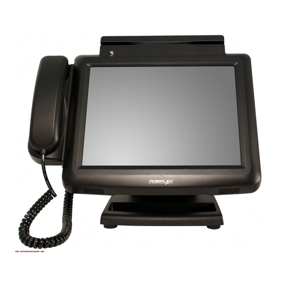
KS-6910/6910TS/6910HS
KS-6910TS
MANUFACTURED BY:
ISO-9001
AN
6,WU-CHUAN RD.,HSIN-CHUANG TEL: 886-2-2991599 (REP.)
(WU-KU INDUSTRIAL ZONE)
TAIPEI HSIEN, TAIWAN
Technical Manual
Rev.: Original
KS-6910
POSIFLEX TECHNOLOGY, INC.
ISO-14001
AND
http://www.posiflex.com
http://www.posiflexusa.com
KS-6910HS
CERTIFIED MANUFACTURER
FAX: 886-2-2991819, 2991808
http://www.posiflex.com.tw
EMAIL: posiflex@posiflex.com.tw
Advertisement
Table of Contents

Related Manuals for POSIFLEX KS-6910


Summary of Contents for POSIFLEX KS-6910
- Page 1 KS-6910/6910TS/6910HS Technical Manual Rev.: Original KS-6910 KS-6910TS KS-6910HS POSIFLEX TECHNOLOGY, INC. MANUFACTURED BY: ISO-9001 ISO-14001 CERTIFIED MANUFACTURER 6,WU-CHUAN RD.,HSIN-CHUANG TEL: 886-2-2991599 (REP.) FAX: 886-2-2991819, 2991808 (WU-KU INDUSTRIAL ZONE) http://www.posiflex.com http://www.posiflex.com.tw TAIPEI HSIEN, TAIWAN http://www.posiflexusa.com EMAIL: posiflex@posiflex.com.tw...
-
Page 2: About This Manual
This manual assists the user especially the software programmer who provides the software system for POS application to utilize the hardware of the KS series which is a member of the POSIFLEX integrated point-of-sale terminal product family. The KS is a compact point-of-sale system that gives the most user friendly application interface by providing a touch control LCD panel and combines the performance and affordability of personal computers with the elegance and reliability of business machine. -
Page 3: Table Of Contents
MSR Life Expectancy................13 System Overall Reliability ...............13 System Definitions..................14 Block Diagram ..................14 Pinouts Definitions ..................17 12 V DC IN 2.5/5.5 CONNECTOR............17 IRQ Assignments ..................22 Peripherals and Accessories ..............23 KP-450 45-Key Programmable Keyboard..........23 Magnetic Stripe Reader ................23 KS-6910/6910TS/6910HS Technical Manual 3... -
Page 4: Ks-6910/6910Ts/6910Hs Technical Manual
Power On/Off Control................27 Peripheral Setup ..................28 ® Posiflex USB Touch Tools .................29 Posiflex USB Touch Manager ..............29 USB Touch Calibrator ................32 USB Touch Edge Acceleration Tool............33 USB Touch Right Button Tool..............34 Hot Key Control Specifications ..............35 Write to MCU ..................35 Read from MCU..................36... -
Page 5: Overview
Owning to its compact size, wall mount readiness, and internet connection capability through LAN or Wi-Fi, the deployment hasn’t been this easy with KS-6910. It also features physical hot-keys for user to directly access frequently used functions like hands-free calling, camera, volume adjustment, emergency alert, and homepage. -
Page 6: Features
Intel processor with DDR3 RAM. Supports storage expansion by SSD and CF card 10-inch resistive touchscreen LCD with 1024x768 resolution Quiet operation and dustproof capability achieved by fan-free design Outstanding heat dissipation capability by aluminum die casting KS-6910/6910TS/6910HS Technical Manual 6... -
Page 7: System Customization Options
One DVD Case, containing one Recovery CD/DVD of preloaded OS (if ordered with preloaded OS), one Wi-Fi driver CD (if ordered with Wi-Fi option), and one User Manual print One 12 V DC 5A Power Adapter with One Power Cord COM1 RS232 terminator plug (KS-6910 / KS-6910TS) KS-6910/6910TS/6910HS Technical Manual 7... -
Page 8: Peripheral Options
VGA Interface: 15 Pin D-SUB with converter cable (P/N: 21862062300) WB-6812 Wall mount kit Fingerprint Sensor (KS-6910TS) Side mounted programmable keypad KP-450 (KS-6910) MSR: 2 or 3 tracks and JIS-II (KS-6910, KS-6910TS) Wi-Fi: 802.11 b/g/n (KS-6910TS/KS-6910HS) KS-6910/6910TS/6910HS Technical Manual 8... -
Page 9: General Specifications
System Power Consumption System Power Output DB9 COM Port + 5 V DC / 1 A max for all ports + 5 V DC / 0.5 Amp max per port USB Port HDD Power Port + 5V DC KS-6910/6910TS/6910HS Technical Manual 9... -
Page 10: Led Indicators
Power Status Off: No power input. Blue: The system is power on. Orange: The system is on standby mode. Missed Call* Off: Normal mode. Flashing: Incoming Call missed. *Must be configured and enabled by dedicated software. KS-6910/6910TS/6910HS Technical Manual 10... -
Page 11: Touchscreen Panel
310 x 269 x 206 (W x H x D) (12.2” x 8.11” x 10.6”) (12.2” x 8.11” x 10.6”) (12.2” x 8.11” x 10.6”) Net Weight 2.82 Kg (6.22 lbs) 3.12 Kg (6.88 lbs) 3.12 Kg (6.88 lbs) KS-6910/6910TS/6910HS Technical Manual 11... -
Page 12: Internet Connections
Storage -20°C to +60°C (-4°F to +140°F) Humidity Operation 20%RH ~ 90%RH, non-condensing Storage 20%RH ~ 90%RH, non-condensing Compliances and Certifications System: CE, FCC, RoHS, WEEE, ISO14001, ISO9001 Power Supply: CE, FCC, WEEE, UL, TUV, PSE KS-6910/6910TS/6910HS Technical Manual 12... -
Page 13: Reliability Specifications
Resistive Touchscreen Life Expectancy Each touch point can sustain more than 10 million touches. MSR Life Expectancy The Magnetic Stripe Reader (MSR) provided by Posiflex can sustain more than 500,000 passes. System Overall Reliability The Mean Time between Failure (MTBF) of the system is 50,000 hours at 90% confidence level. -
Page 14: System Definitions
Giga LAN AC97 CODEC Port RTL 8111DL Lineout Realtek ALC 662 USB 2.0 Parallel USB0 SUPER I/O Debug Fintek F81865 USB1 Cash CR Port USB2 Drawer USB3 COM1 DB9M COM2 Touch DB9M Wi-Fi COM3 RJ45 COM4 (internal) KS-6910/6910TS/6910HS Technical Manual 14... - Page 15 Realtek ALC 662 Port RTL 8111DL USB 2.0 Parallel Lineout USB0 Handset Speaker SUPER I/O Debug Fintek F81865 USB1 Handset Cash CR Port USB2 Drawer Internal USB3 COM1 DB9M COM2 Touch DB9M Wi-Fi COM3 RJ45 COM4 (internal) KS-6910/6910TS/6910HS Technical Manual 15...
- Page 16 USB 2.0 Lineout Parallel USB0 Handset Speaker SUPER I/O USB1 Debug Handset Fintek F81865 USB2 Cash CR Port Internal Drawer USB3 COM1 DB9M Touch COM2 DB9M Wi-Fi COM3 Camera RJ45 COM4 Fingerprint Sensor (internal) Hotkeys μP COM5 KS-6910/6910TS/6910HS Technical Manual 16...
-
Page 17: Pinouts Definitions
Most usual observation is IRQ 11. Green Orange PIN # Definition for 10/100Mbps Definition for 1Gbps TD + DA + TD - DA - RD + DB + DC + DC - RD - DB - DD + DD - KS-6910/6910TS/6910HS Technical Manual 17... - Page 18 ※ To ensure CR port functioning normally, Com1 (DB9M) must be connected all time, either with a peripheral or a RS232 Terminator Plug (P/N: 21700009141). Pin # Definition DRAWER KICK 1 DRAWER OPEN SENSE +POWER DRAWER KICK 2 KS-6910/6910TS/6910HS Technical Manual 18...
- Page 19 4. Press Enter key to edit, select Enabled, and then press Enter to apply the selection. 5. Press F10 to save the changes and exit BIOS setup. *5V DC output is disabled by default. KS-6910/6910TS/6910HS Technical Manual 19...
- Page 20 3. On Intel tab, select the option COM3 – 5V output. 4. Press Enter to edit, select Enabled, and then press Enter to apply the selection. 5. Press F10 to save the changes and exit BIOS setup. *5V DC output is disabled by default. KS-6910/6910TS/6910HS Technical Manual 20...
- Page 21 System Definitions: SATA HDD Connector Pin # Definition 7654321 HDD POWER CONNECTOR This connector is a small 4 pin connector with housing 3 2 1 Pin # Definition + 5 VDC KS-6910/6910TS/6910HS Technical Manual 21...
-
Page 22: Irq Assignments
1, 2, 3 …) you wan to configure. 3. Press Enter to edit, select the IRQ you want to assign with, and then press Enter to apply the change. 4. Press F10 to save the changes and exit BIOS setup. KS-6910/6910TS/6910HS Technical Manual 22... -
Page 23: Peripherals And Accessories
Peripherals and Accessories: KP-450 45-Key Programmable Keyboard Peripherals and Accessories KP-450 45-Key Programmable Keyboard To be installed on the side of KS-6910 or KS-6910TS. 29 programmable keys with 15 numeric keys (including 1 double key) place a Magnetic Stripe Reader... - Page 24 Display color Total Height 200 mm Total Width 221 mm 110 mm Total Depth Display Head Height 57.5 mm Display Head Width 196.6 mm 39.5 mm Display Head Height Case color Black, Ivory Connection Interface RS-232 KS-6910/6910TS/6910HS Technical Manual 24...
-
Page 25: Wall Mount Kit Wb-6812
4. In future removal of the main unit from the bracket, please remember to raise the main unit, move it to the right and further raise it up to allow matching pegs to come out of the matching holes. KS-6910/6910TS/6910HS Technical Manual 25... - Page 26 5. For alternative application of the bracket to a VESA joint mechanism instead of the rigid wall, please screw the bracket to the joint mechanism at appropriate set of metal bosses in center of backside of the bracket. KS-6910/6910TS/6910HS Technical Manual 26...
-
Page 27: Application Guides
3. Select Resume Time, type the time when you want the system to wake up (e.g. 23:59:59). After Power Failure This option decides how the system reacts to an accidental power loss. To configure, 1. Under Power tab, select After Power Failure, and then press Enter to edit. KS-6910/6910TS/6910HS Technical Manual 27... -
Page 28: Peripheral Setup
2.5” SATA HDD in main unit to have an optional 2.5” SATA HDD in base or to use a SATA SSD or an internal CF memory card reader instead of the default HDD. Please check the BIOS setting accordingly if the configuration has been changed. KS-6910/6910TS/6910HS Technical Manual 28... -
Page 29: Posiflex Usb Touch Tools
Posiflex® USB Touch Tools: Posiflex USB Touch Manager ® Posiflex USB Touch Tools Posiflex USB Touch Tools is a set of software applications that can help to improve ® user experience with touch screen on Posiflex systems. Posiflex USB Touch Manager serves as the portal of the other tools and a touchscreen settings manager. - Page 30 *Delay can be adjusted in Time delay for Touch_to_Calibrate under General settings with at least 5 seconds delay. **5 seconds are given to abort being directed to Posiflex USB Touch Calibrator. Enable Buzzer When selected, the buzzer beep sounds every time a touch is made.
- Page 31 Posiflex® USB Touch Tools: Posiflex USB Touch Manager selected. ** The beep can not be muted in Posiflex USB Touch Calibrator even this option is selected. Touch mode settings Mouse Emulation As finger or stylus gently touches and slide, the cursor moves as if manipulating with a mouse.
-
Page 32: Usb Touch Calibrator
2. Click Start to proceed to calibration process, otherwise click Exit to quit. 3. As onscreen instructions suggest, touch on the center of each crosshair mark 4. The calibration takes five steps, and ends in returning to Posiflex USB Touch Calibration Utility dialog box. -
Page 33: Usb Touch Edge Acceleration Tool
Posiflex® USB Touch Tools: USB Touch Edge Acceleration Tool USB Touch Edge Acceleration Tool Sometimes we need to move the cursor to the very edge of the screen, like reaching ® for the hidden task bar in Windows . USB Touch Edge Acceleration Tool helps to move the cursor to the edge of the screen, because the edge of the touch panel can be difficult to touch with finger or even stylus. -
Page 34: Usb Touch Right Button Tool
Posiflex® USB Touch Tools: USB Touch Right Button Tool USB Touch Right Button Tool Posiflex USB Touch Right Button can emulate screen touch as right-clicking. To do so, 1. Run USB Touch Right Button Tool. 2. Click One-Shot Right Button, and then the next touch on the screen would act as right-click. -
Page 35: Hot Key Control Specifications
“V&” ( &= 0~9, DEFAULT&=5; 0=mute, 9=MAX) Volume adjustment “T” (e.g. E0H1B0C0A0U0D0X5) MCU to report status every second “Q” MCU to stop reporting status “S” (e.g. E0H1B0C0A0U0D0X5) MCU to report current status once “F1” Message LED Flashing “F0” (Default) Message LED Off KS-6910/6910TS/6910HS Technical Manual 35... -
Page 36: Read From Mcu
Camera Button not pressed “A0” (Default) Camera Button pressed “A1” Speaker Up Button not pressed “U0” (Default) Speaker Up Button pressed “U1” ,“X&”(&=0 to 9) Speaker Down not pressed “D0” (Default) Speaker Down pressed “D1”, “X&”(&=0 to 9) KS-6910/6910TS/6910HS Technical Manual 36... -
Page 37: Disassembly And Replacement
1. Place the terminal on a flat surface with LCD panel facing down. 2. Remove the two screws of the HDD/SDD cover on the back KS-6910 series model, as shown in the picture. 3. Remove the two screws securing the HDD/SSD, as shown in the picture. -
Page 38: Replacing Main Board
2. Unplug all the connectors from the main board. It’s highly recommended to label the connectors before disconnecting them. 3. Remove all the screws on the main board, and separate the main board from the chassis. KS-6910/6910TS/6910HS Technical Manual 38... -
Page 39: Hardware Details
Hardware Details: Main Board Hardware Details Main Board KS-6910/6910TS/6910HS Technical Manual 39... - Page 40 Hardware Details: Main Board BOTTOM KS-6910/6910TS/6910HS Technical Manual 40...
-
Page 41: Jumpers And Connectors
Short: COM1 outputs 5V (Default) Short: COM1 = RI Short: COM2 outputs 5V (Default) Short: COM2 = RI JCMOS1 CMOS Data Control Short: Normal (Default) Short: Clear CMOS Refer to Pinouts Definitions. Refer to Pinouts Definitions. KS-6910/6910TS/6910HS Technical Manual 41... - Page 42 LVDS1 Panel header for 10’’ LCD MIC-IN1 Microphone phone in header MS_LED1 Message LED header. MSR1 USB MSR header 12v dc-in SATA_PWR1 External SATA port power connector External SATA port 7 pin connector--- SO-DIMM1 Dram connector KS-6910/6910TS/6910HS Technical Manual 42...
- Page 43 Hardware Details: Jumpers and Connectors SPKL Speaker header L SPKR Speaker header R Power switch TOUCH1 Touch panel 5 pin USB1 Dual high stack USB port USB2 Dual high stack USB port VGA1 External VGA connector WIFI External WI-FI connector KS-6910/6910TS/6910HS Technical Manual 43...
-
Page 44: Spare Parts List
16440304013 Left Side Cover for KS-6910/HS/TS, Black 16440302013 Plastic HDD Cover for KS-6910/HS/TS, Black 10684038103 Binding Head Screw, #6/32-10L SW+W-NiB 2.5" SATA HDD Kit for KS-6910/HS/TS, w/HDD 160GB, w/o Cable 36444003010 (In Main Unit) 21955016003 2.5" SATA HDD160G 36444031000 SATA SSD Module Upgrade Kit, w/o SSD 21943008002 1"... - Page 45 Hinge, Black 21863261500 USB I/O Cable, L=150mm, Black 16550307017 Power Button, Blue Main Board for KS-6910, w/ CPU Pine View-D SC 1.8G (Single Core), 46440606210 Ver.B0 Main Board for KS-6910, w/ CPU Pine View-D DC 1.8G (Dual Core), 46440616210 Ver.B0 KS-6910/TS/HS M/B w/ CPU Pine View-D SC 1.8G (Single Core) &...
- Page 46 Power Cord for India,3 Wire, IEC 320-C13 NON06 21868901300 Power Cord for Argentina,3 Wire, L=1800mm, IEC320-C13 NON07 16440512110 Carton for 10" POS System NON08 16440543010 PE Foam for KS-6910 NON09 16440901020 User Manual for KS-6910/TS/HS KS-6910HS Spare Parts List Pos. Part Number Description 36594027003...
- Page 47 10244215801 Releasable Cable Tie 8*151mm Pan Head Self-Tapping Screw,∮3-10L 10528030102 10266020272 Rubber Foot ,20*7mm, Black 38326004003 Base Stand Assembly for LM/TM-2008/KS-6910, Black 38326004006 Base Stand Assembly for LM/TM-2008/KS-6910, Ivory 16550304013 Plastic Neck Cover, Black 16550304016 Plastic Neck Cover, Ivory 16550306023...
- Page 48 Right Camera Support for KS-6910HS, Ivory 16440103010 Fingerprint Bracket for KS-6910HS 16440105010 LCD Holder for KS-6910 16440313013 Plastic HotKey for KS-6910, Black 16440313016 Plastic HotKey for KS-6910, Ivory 46443502110 HotKey Board, Rev.A0 21864055501 12 Pin FFC Cable for EP/HK, L=300 mm...
- Page 49 16440510110 Carton for 10" POS System NON07 10331201305 PE Bag, 135*200*0.05mm NON08 16440540010 PE Foam for KS-6910HS/TS NON09 16440901020 User Manual for KS-6910/TS/HS NON09 16440900110 Traditional Chinese Manual for KS-6910TS/HS KS-6910TS Spare Parts List Pos. Pos. Pos. Pos. 36594027003 Handset Assembly for KS-6810/6910, Black...
- Page 50 10241300071 10244215801 Releasable Cable Tie 8*151mm Pan Head Self-Tapping Screw,∮3-10L 10528030102 10266020272 Rubber Foot ,20*7mm, Black 38326004003 Base Stand Assembly for LM/TM-2008/KS-6910, Black 16550304013 Plastic Neck Cover, Black 16550306023 Plastic Hinge Cover, Black 10684038123 Binding Head Screw #6/32-12L SW+W-NiB 10684038082...
- Page 51 Pan Head Screw M2-8L(Ni) 36595000020 RJ9 Phone Jack Kit for KS-6810HS/6910TS/6910HS Binding Head Self-Tapping Screw,∮3-10L 10524030102 18060101010 Switch Bracket 16440105010 Right LCD Holder for KS-6910 18060302013 Handset Base Hook, Black 36444019000 10.1” Touch Panel Assembly, w/Packing 36444020000 10.1" LCD Panel, w/Packing 36444021000 10.1"...
-
Page 52: Assembly Drawing
Spare Parts List: Jumpers and Connectors Assembly Drawing KS-6910 KS-6910HS KS-6910/6910TS/6910HS Technical Manual 52... - Page 53 Spare Parts List: Jumpers and Connectors KS-6910TS KS-6910/6910TS/6910HS Technical Manual 53...
Need help?
Do you have a question about the KS-6910 and is the answer not in the manual?
Questions and answers