Table of Contents
Advertisement
Quick Links
User and maintenance instructions
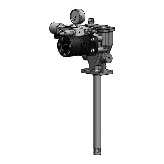
FlowMaster II rotary driven
hydraulic pump series "A"
Liebherr models 85732-AU, 60 lbs (27 kg), 85733-AU, 120 lbs (54 kg), 85734-AU, 400 lbs (181 kg)
85886, 60 lbs (27 kg), 85887, 120 lbs (54 kg), and 85888, 400 lbs (181 kg) *
Model 85732-AU shown *
Date of issue
August 2023
Form number
404554-AU
Version
5
*
Indicates change.
Advertisement
Table of Contents

Related Manuals for Lincoln SKF FlowMaster II 85732-AU


Summary of Contents for Lincoln SKF FlowMaster II 85732-AU
- Page 1 User and maintenance instructions FlowMaster II rotary driven hydraulic pump series “A” Liebherr models 85732-AU, 60 lbs (27 kg), 85733-AU, 120 lbs (54 kg), 85734-AU, 400 lbs (181 kg) 85886, 60 lbs (27 kg), 85887, 120 lbs (54 kg), and 85888, 400 lbs (181 kg) * Model 85732-AU shown * Date of issue August 2023...
-
Page 2: Table Of Contents
Contents Declaration of Incorporation * ..U.K. Declaration of Incorporation * . . Safety * ......Overview . -
Page 3: Declaration Of Incorporation
I, the undersigned of Lincoln Industrial Corporation, do hereby declare that the equipment specified above, in its intended use, conforms to the requirements of the above EC Directive(s) and Harmonized Standards and Directives above. -
Page 4: U.k. Declaration Of Incorporation
I, the undersigned of Lincoln Industrial Corporation, hereby declare that the equipment specified above, in its intended use, conforms with the Essential Health and Safety Requirements of U.K. legislation Supply of Machinery (Safety) Regulations 2008 No. 1597 Annex I, Declaration of Incorporation by the time of placing it on the market. -
Page 5: Safety
Safety * Explanation of signal CAUTION words for safety Do not operate equipment without wearing personal protective gear. The assembly must be installed, maintained Wear eye protection. Protective and repaired exclusively by persons familiar equipment such as dust mask, non-skid with the instructions. -
Page 6: Overview
Overview Appropriate use Diagram 2, page 8 details grease output in proportion to the hydraulic input that is affected by temperature. This service page details the procedure that All models are designed to pump and The models 85732-AU, 85733-AU and must be followed while installing, operating dispense lubricants using hydraulic power. -
Page 7: Inspection
Inspection If over pressurizing of equipment is believed to have occurred, contact nearest factory authorized warranty and service center for inspection of pump. Specialized equipment and knowledge is required for repair of pump. Annual inspection by nearest factory authorized warranty and service center is recommended. - Page 8 Diagram 1 Hydraulic schematic Item Description Hydraulic fluid inlet port SAE 4 ORB Hydraulic fluid return to tank SAE 6 ORB Hydraulic motor Lube outlets in NPTF Flow control valve Pressure gauge Hydraulic fluid to vent valve Orifice 0.013 in (0.33 mm) diameter Pressure reducing valve Solenoid valve Diagram 2...
- Page 9 Fig. 1 * Pump dimensions 2.72 in (69 mm) Ø 1.25 in Model (Ø 32 mm) 85732-AU 12.88 in 10.38 in 8.88 in 19.05 in 30.39 in (327 mm) (264 mm) (226 mm) (484 mm) (722 mm) 85733-AU 12.88 in 10.38 in 8.88 in 27.56 in...
-
Page 10: Install Pump
Fig. 2 Model 85732-AU shown * Item Description Hydraulic fluid inlet port SAE 4 ORB Hydraulic fluid return to tank SAE 6 ORB Lube outlet Pressure gauge Manifold Solenoid valve Solenoid coil (24 V Flow regulator Pressure reducing valve Hydraulic motor Indicates change. -
Page 11: Operation
Operation NOTE NOTE Do not exceed maximum operating Refer to Pressure control valve temperature of hydraulic fluid adjustment, page 12, for instructions to 250 °F (121 °C). adjust pressure and flow. Fig. 3 depicts Do not allow pump to run dry of location of operating valves for pump. -
Page 12: Set Pump Manifold Pressure And Flow Controls
Set pump manifold Adjust flow control valve Crankcase fluid service interval pressure and flow 1 Loosen hex head nut on flow controls (85732-AU, regulator (69) (→ Fig. 4). • Use Moly Pure ISO 68 pure synthetic 2 Adjust flow by turning hex head screw on motor fluid or equivalent, 15 oz (0.44 l). -
Page 13: Disassembly
Disassembly Fig. 5 Model 85732-AU shown * NOTE As parts are removed, place on clean surface in order removed from pump. 34 35 This will help with assembly of pump. NOTE Do not reuse soft parts. Use new parts from soft parts kit if pump is disassembled. - Page 14 Fig. 7 16 Remove o-rings (54 and 53) and back-up washer (52) from outlet pin nuts (55). Refer to fig. 7. 17 Remove screws and washers (44,45) holding shaft cover and o-ring (46,47) on pump housing (37). NOTE Key-way (39) should be pressed into pump shaft (40).
- Page 15 Fig. 8 26 Remove bronze bearing (56) from tube housing (60) (→ Fig. 8). 27 Remove o-ring (59) from tube housing (60). 28 Remove o-ring (57) from tube housing (60). 29 Remove back-up washer (58) from tube housing (60).
-
Page 16: Crank Rod And Eccentric
Crank rod and 4 Place outlet pin (8) in vise. 16 Remove plunger (24a) from plunger link 5 Using T1 tool, loosen but do not remove rod (20). eccentric lower plunger (24a) from plunger link 17 Remove upper plunger (10a) from rod (20). -
Page 17: Crank Rod
Fig. 10 3 Remove ball cage (28), check ball (29) and o-ring seal (27) from check seat housing (30) (→ fig. 10). 4 Remove lower bushing (24b) from reciprocating tube (25). 5 Remove lower cup seal (26) from reciprocating tube (25). Crank rod 1 Loosen and remove flat head screws (1) from eccentric (5) (→... -
Page 18: Assembly
Assembly Fig. 12 Crank rod and eccentric 1 Place crank rod (7) on 2 in (62 mm) diam- eter steel pipe, provided in tool kit 276275 (→ fig. 13). 2 Install ball bearing assembly (6) into crank rod (7). 3 Place eccentric (5) in ball bearing (6). 4 Place one end of inner retaining ring (4) on top of eccentric (5). -
Page 19: Pump
Pump 5 Install steel back-up ring (17) onto upper 14 Place new u-cup seal (16) with flat-side bushing (10b). facing inside wrist pin anchor (13). 1 Install ball (23) into lower plunger (24a) 6 Slide o-ring (18) onto upper 15 Clean threads of wrist pin anchor (13). (→... - Page 20 24 Install cup seal (26) with flat-side facing cating tube (25) and tighten using 37 Torque bushing screws (11) to 110 to 125 end of tube (25) (→ fig. 15). in (9 mm) hex key. in-lbf (12.4 to 14.1 Nm). 25 Place new o-ring (27) on lower 32 Torque to 20 to 25 ft-lbf (27 to 33 Nm).
- Page 21 Fig. 17 38 Insert new o-ring (59) onto outer 44 While aligning key (39) on pump shaft (40) diameter of housing tube (60) with eccentric key way (5), slide (→ fig. 17). shaft (40) into eccentric (5). 39 Place back-up washer (58) into housing tube (60).
- Page 22 Fig. 18 45 Install retaining ring (48) on pump shaft (40) (→ fig. 18). 46 Place new o-ring (47) on bearing cover (46). 47 Install bearing cover (46) on pump (37). 48 Insert and thread screws (44) with lock washers (45) into shaft cover (46) and pump housing (37).
- Page 23 Fig. 20 57 Install new cover gasket (36) on pump housing (37) (→ fig. 19). Model 85732-AU shown * 58 Install pump cover (35). 59 Thread screws (33) with new o-rings (34) into pump cover (35). 60 Torque screws (33) to 10 to 15 in-lbf (1.1 to 1.6 Nm).
-
Page 24: Troubleshooting
Troubleshooting Condition Possible cause Corrective action Pump does not run No pressure on gauge (64) Open shut off valve Closed supply line shut off valve • No power to solenoid valve (68) Correct electrical fault • Faulty solenoid (68) Replace solenoid (68) •... - Page 25 Fig. IPB 1...
- Page 26 Fig. IPB 2...
- Page 27 Fig. IPB 3 Model 85732-AU shown * Indicates change.
- Page 28 Parts list Item Description Part number Quantity Item Description Part number Quantity Flat head screw ( –28 × 1 270635 Pump shaft 277397 Counter weight 272197 Retaining ring 272561 Retaining ring 270609 Ball bearing 272556 Retaining ring 270608 Shaft seal 272554 Crank eccentric 270666...
-
Page 29: Warranty
® SKF and Lincoln are registered trademarks of the SKF Group. © SKF Group 2023 The contents of this publication are the copyright of the publisher and may not be reproduced (even extracts) unless prior written permission is granted. Every care has been taken to ensure the accuracy of the information contained in this publication but no liability can be accepted for any loss or damage whether direct, indirect or consequential arising out of the use of the information contained herein.
Need help?
Do you have a question about the SKF FlowMaster II 85732-AU and is the answer not in the manual?
Questions and answers