Lincoln SKF FlowMaster II A Series User And Maintenance Instructions
Rotary driven hydraulic pump
Hide thumbs
Also See for SKF FlowMaster II A Series:
- Operation manual (48 pages) ,
- User and maintenance instructions (28 pages) ,
- User and maintenance instructions (24 pages)

Related Manuals for Lincoln SKF FlowMaster II A Series


Summary of Contents for Lincoln SKF FlowMaster II A Series
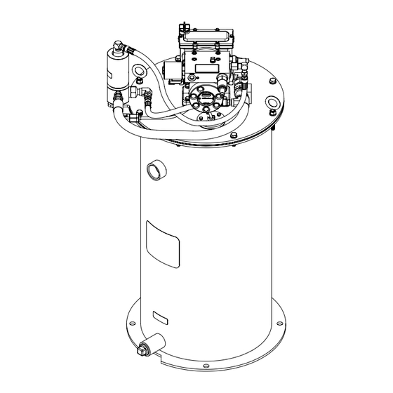
- Page 1 User and maintenance instructions FlowMaster II rotary driven hydraulic pump Model 85722-AU*, 85764 and 85764-AU*, series “A” Model 85764 shown * Date of issue January 2021 Form number 404561 Version * Indicates change.
-
Page 2: Table Of Contents
Contents EC Declaration of Conformity* ..Safety ......Explanation of signal words for safety . -
Page 3: Ec Declaration Of Conformity
Conformity in accordance with Machinery Directive 2006/42/EC, Annex II Part 1 A* The manufacturer Lincoln Industrial, 5148 N. Hanley Road, St. Louis, MO, 63134 USA, hereby declares that the machine Designation: FlowMaster II series A Type: rotary driven hydraulic pump Models: 85764, 85764-AU and 85722-AU, series “A”... -
Page 4: Safety
Safety Explanation of signal words for safety • Read and carefully observe these installation instructions before installing, operating or troubleshooting FlowMaster NOTE II rotary driven hydraulic pump. Assembly Emphasizes useful hints and must be installed, maintained and recommendations as well as repaired exclusively by persons familiar information to prevent property damage with instructions. -
Page 5: Description
Description* Appropriate use Operation with system controller Model 85764, 85764-AU and 85722-AU are • Pump on this unit is exclusively designed pumping units designed to operate a to pump and dispense lubricants using Centro-Matic lubrication system. Units hydraulic power only. Operation with lube system controller is include a vent valve to relieve line pressure •... -
Page 6: Dimensions
Fig. 1* Model 85764 and 85764-AU dimensions 19.0 in 16 / in (425 mm) (483 mm) 15 / in (394 mm) / in (15 mm) apart 18.8 in (477 mm) 45° 38.4 in (975 mm) Indicates change. - Page 7 Fig. 2* Model 85722-AU dimensions 18.9 in ∅ 15.1 in (384 mm) (479 mm) ∅ 13.8 in (352 mm) 18.2 in (462 mm) ∅ 0.50 in (13 mm) 40° 20° 31.6 in (802 mm)
-
Page 8: Installation
Installation Operation Fill reservoir Place unit in approximate location making sure electric and hydraulic power connections are accessible. 1 Clean area around filling port. 2 Remove lower and upper pipe plugs 1 Mark center locations of four holes at from side of reservoir. bottom of reservoir. -
Page 9: Maintenance And Repair
Maintenance and Outlet check service Vent valve service repair Refer to Troubleshooting (page 18) to Refer to Troubleshooting (page 18) to determine if outlet check valve (6) is cause determine if vent valve is cause of failure of failure. († Fig. 2, page 11; Fig. 6 and Fig. 8, General maintenance Pump will not build up sufficient lubricant page 12). -
Page 10: Follower
Follower Grease level sensor Safety unloader valve If follower foam appears to be damaged or If grease level sensor is not detecting proper Safety unloader valve (1) († Fig. 2, page 11) does not wipe sides of container effectively grease level, there are several possible is not serviceable. -
Page 11: Reservoir Cover
Fig. 3 Fig. 5 Reservoir cover Reservoir assembly (16) Fig. 4 Fig. 6 Outlet check assembly (6) Model 85764 level sensor (33)* NPTF... -
Page 12: Level Sensor
Fig. 7 Fig. 9 Fig. 11 Hydraulic vent valve mount Hydraulic vent valve (20) Model 85722-AU low-level indicator* Fig. 8 Fig. 10 Follower assembly (35) Model 85764 cover plug*... -
Page 13: Follower Assembly
Fig. 12 Model 85764 follower assembly (35)* Stagger long bolts and small bolts on follower plate. Indicates change. -
Page 14: Model 85764 Follower Assembly
Fig. 13* Model 85722-AU follower assembly (35) Indicates change. -
Page 15: Model 85764 And 85764-Au
Fig. IPB 1* Model 85764 and 85764-AU B–B 20 21 22 23 27, 28 24, 25 12, 13 18, 19 31, 32 A–A Indicates change. -
Page 16: Model 85722-Au
Fig. IPB 2* Model 85722-AU 27, 28, 77 23, 24 12, 13 31, 32 18, 19 Indicates change. -
Page 17: Parts List
Parts list Model 85764, Model Model 85764, Model Item Description 85764-AU* 85722-AU* Qty. Item Description 85764-AU* 85722-AU* Qty. Safety unloader, 90942 90942 Outlet check bushing 90204 2) 3) 90204 2) 3) 4 000 psi (275 bar) Nipple, 14727 14727 Pump check disc 80206 2) 3) 80206... -
Page 18: Troubleshooting
Troubleshooting Condition Possible cause Corrective action Pump does not operate. No hydraulic power to pump. Turn on or connect hydraulic supply to pump. No pressure on gauge: • Closed supply line shut off valve. Open shut-off valve. • No power to solenoid valve. Correct electrical fault. - Page 19 This page left intentionally blank.
-
Page 20: Warranty
® SKF and Lincoln are registered trademarks of the SKF Group. © SKF Group 2021 The contents of this publication are the copyright of the publisher and may not be reproduced (even extracts) unless prior written permission is granted. Every care has been taken to ensure the accuracy of the information contained in this publication but no liability can be accepted for any loss or damage whether direct, indirect or consequential arising out of the use of the information contained herein.
Need help?
Do you have a question about the SKF FlowMaster II A Series and is the answer not in the manual?
Questions and answers