Table of Contents
Advertisement
Quick Links
Operating Instructions
Piston pump units
PE-99(W)-EX; PEF-99(W)-EX; PE-99W-S1-EX; PF-23-2(2)-EX; PFP-23-2(2)-EX
Created on:
07.03.2023
Document no.:
951-180-198-EN
Version:
01
Read these instructions before
installation or start-up of the
product and keep them readily
available for later consultation!
Advertisement
Table of Contents

Related Manuals for Lincoln SKF PE-99-EX


Summary of Contents for Lincoln SKF PE-99-EX
- Page 1 Operating Instructions Piston pump units PE-99(W)-EX; PEF-99(W)-EX; PE-99W-S1-EX; PF-23-2(2)-EX; PFP-23-2(2)-EX Created on: 07.03.2023 Document no.: 951-180-198-EN Version: Read these instructions before installation or start-up of the product and keep them readily available for later consultation!
- Page 2 EU Declaration of Conformity in accordance with Directive 2014/34/EU, Annex X The manufacturer hereby declares under its sole responsibility conformity of the product described below with all relevant harmonization legislation of the European Union and with the essential health and safety requirements of the Machinery Directive 2006/42/EC, Annex I which are marked as applicable in the Annex to the Declaration of Conformity and which are fulfilled at the time of placing on the market.
- Page 3 Appendix to Declaration of Conformity in accordance with 2006/42/EC, Annex II, No. 1 B Description of the essential health and safety requirements according to 2006/42/EC, Annex I, which have been applied and fulfilled: Table 1 Appendix to Declaration of Incorporation No.: Essential health and safety requirement Applicable:...
-
Page 4: Masthead
SKF (U.K.) Limited, 2 Canada Close, Banbury, Oxfordshire, OX16 2RT, GBR. - North America - SKF Lubrication Business Unit Lincoln Industrial 5148 North Hanley Road, St. Louis, MO. 63134 USA - South America - SKF Argentina Pte. Roca 4145, CP 2001 Rosario, Santa Fe... -
Page 5: Table Of Contents
5.2 Return shipment ..............20 Table of contents 5.3 Storage ..................20 5.4 Storage temperature range ..........20 Masthead ....................4 5.5 Storage conditions for products filled with lubricant ..20 Table of contents .................. 5 5.5.1 Storage period up to 6 months ....... 20 Safety alerts, visual presentation, and layout ......... - Page 6 11.2 Troubleshooting..............43 12. Repairs ..................44 13. Shutdown, disposal ..............44 13.1 Temporary shutdown ............44 13.2 Permanent shutdown, disassembly ........44 13.3 Disposal .................. 44 14. Spare parts .................. 44 15. Appendix ..................45 15.1 Cable colors in accordance with IEC 60757 ....45 15.2 China RoHS Table ..............
-
Page 7: Safety Alerts, Visual Presentation, And Layout
1. Instruction steps: These indicate a chronological sequence Safety alerts, visual of instruction steps. The numbers of the steps are in bold and are followed by a period. If a new activity follows, the presentation, and layout numbering starts again at “1.” –... -
Page 8: Safety Instructions
1.3 General behaviour when handling the 1. Safety instructions product 1.1 General safety instructions • Familiarize yourself with the functions and operation of the product. The specified assembly and operating steps and their • Putting the products into operation or operating them without sequences must be observed. -
Page 9: Foreseeable Misuse
during transport, installation, start-up, operation, maintenance, • Use with a finish or paint coat applied improperly after repair and disassembly. delivery. The finish or paint coat must meet the requirements of the standards applicable to ATEX. Operator • Use in potentially explosive gases and vapors whose ignition temperature is less than 125% of the maximum surface A person competent due to training, knowledge, and experience to execute the functions and activities associated with normal... -
Page 10: Safety Markings On The Product
1.10 Safety markings on the product 1.13 Note on Low Voltage Directive The protection objectives of the Low Voltage Directive Table 2 2014/35/EU are met in accordance with Annex I, No. 1.5.1 of Markings on the product the Machinery Directive 2006/42/EC. <Co ntent>... -
Page 11: First Start-Up, Daily Start-Up
If guards or safety devices need to be removed, they must be • Use only ESD tools and ESD clothing approved for use in reinstalled immediately following conclusion of work and then potentially explosive atmospheres. checked for proper function. • All painted components of the products we supply are painted Check new parts for compliance with the intended use before in accordance with the requirements of DIN EN 60079- 0:2014 (electrostatic discharge). -
Page 12: Operation In Potentially Explosive Atmospheres
conductive metal contact with the attachments and with the • Improper usage main machine. • Unauthorized alterations • With SSV-E and SSVD-E progressive metering devices, • Use of spare parts or components other than original SKF emergency lubrication via the grease fitting is permissible spare parts or components only if the pump is grounded to the same potential or if it can •... - Page 13 Table 3 Residual risks Residual risk Possible in lifecycle Avoidance / Remedy Generation of electrostatic charges, E F G H Always use ESD clothing and ESD tools within potentially sparks due to unsuitable clothing or explosive atmospheres tools Generation of electrostatic charges, E F G H Secure parts against falling.
-
Page 14: Lubricants
• The lubricant’s ignition temperature has to be at least 2. Lubricants 50 kelvin above the maximum surface temperature of the components. 2.1 General information 2.6 Solid lubricants Lubricants are selected specifically for the relevant application. The manufacturer or operator of the machine should ideally Solid lubricants may only be used after prior consultation with make the selection in consultation with the supplier of the SKF. -
Page 15: Overview, Functional Description
3.3 Calculating the lubricant 3. Overview, functional requirements of a centralized lubrication description system 3.1 General The lubricant requirements of a centralized lubrication system are roughly calculated according to the following formula. Piston pump units feed lubricant to the consuming points of the centralized lubrication system. -
Page 16: Automatic Fill Level Monitoring With Dynamic Pressure Transducer
3.5.2 Automatic fill level monitoring with NOTE dynamic pressure transducer In terms of its electrical design, the electrical float switch contains only passive elements and thus no ignition source. Fig. 3 The switch position is evaluated via a magnetically actuated reed switch. -
Page 17: Visual Fill Level Monitoring
The dynamic pressure transducer used in the piston pump unit (PEF) is supplied with feed air pressure (p1) (Fig. 3) via the connection PC (black). NOTE Recommended feed air pressure 0.1 to 0.15 bar. If the reservoir is filled with lubricant, a corresponding signal air pressure (p2) (Fig. -
Page 18: Technical Data
4. Technical data 4.1 General technical data Table 5 Version PE-99(W)-EX PE-99W-S1-EX PEF-99(W)-EX PF-23-2(2)-EX PFP-23-2(2)-EX Explosion protection marking for all II 2G Ex h IIB T4 Gb designs II 2D Ex h IIIC T 135 °C Db Permissible ambient temperature 10 °C to 60 °C 10 °C to 60 °C 10 °C to 60 °C... -
Page 19: Tightening Torques
Table 5 Version PE-99(W)-EX PE-99W-S1-EX PEF-99(W)-EX PF-23-2(2)-EX PFP-23-2(2)-EX Feed air pressure PC 0–8 bar (recommended: 0.1–0.15 bar) Signal pressure AC 0–8 bar Connection PC / AC Plug nipple for tube NW 3 * The electrical connection must be made by qualified and authorized persons, using an intrinsically safe circuit with a suitable isolating amplifier. -
Page 20: Delivery, Returns, Storage
5.5 Storage conditions for products filled 5. Delivery, returns, storage with lubricant 5.1 Delivery For products filled with lubricant, the permitted storage temperature range is: After receipt of the shipment, it must be inspected for any minimum + 5 °C [+41 °F] shipping damage and for completeness according to the maximum... - Page 21 Due to statutory provisions and for the safety of our employees and operation facilities we further need a fully completed and signed “Declaration of decontamination”.
-
Page 22: Assembly
6. Assembly NOTICE Pressure Damage or injury due to excessive pressure 6.1 General The maximum primary air pressure indicated for operation Only qualified technical personnel may install, operate, of the lubrication unit may not be exceeded. maintain, and repair the products specified in the instructions. The product should, to the extent possible, be protected from 6.5 Lubrication line routing humidity and vibration, and should be mounted so that it is... -
Page 23: Assembly Of Pe-99(W)-Ex
relief valve. For operating pressures up to 45 bar, as can occur cutting-sleeve screw unions conforming to DIN 2353 can be especially in single-line piston metering systems, SKF fittings for used. If using fittings from other manufacturers, pay careful solderless pipe unions can be used (double or single cone rings). attention to the assembly instructions and technical For higher operating pressures up to 250 bar as can occur specifications provided by the manufacturer. -
Page 24: Pressure Diagram
6.7.4 Pressure diagram NOTICE Fig. 7 Dust load Damage due to dust in the area of the spring In areas with heavy dust load, additionally provide a suitable air filter for ventilation/bleed line P4 to prevent the ingress of dust into the spring chamber Fig. -
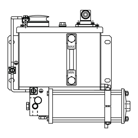
Page 25: Electrical Connection
Fig. 9 Dimensions of PE-99(W)-EX / PE-99W-S1-EX 6.7.6 Electrical connection The electrical connection must be carried out by qualified and authorized persons, using an intrinsically safe circuit with a suitable isolating amplifier. Install the isolating amplifier outside of potentially explosive atmospheres or in areas for which it is identified as being suitable. -
Page 26: Filling The Pe-99(W)-Ex Piston Pump Units
Fig. 10 6.7.7 Filling the PE-99(W)-EX piston pump units Fig. 11 Wiring diagram Filling PE-99(W)-EX piston pump units Legend to Figure 10: PE-99(W)-EX 1. Open the filler socket (1) 1 Max. 36 V DC 2. Fill the reservoir with the planned lubricant up to the -MAX- 2 Minimum mark (2) 3 Pre-warning... -
Page 27: Assembly Of Pef-99(W)-Ex
6.8 Assembly of PEF-99(W)-EX Fig. 12 Assembly holes, pressure lines, and equipotential bonding connections for PEF-99(W)-EX explosion hazard area. In case of heavy dust load, additionally 6.8.1 Assembly holes secure with an air filter. The product is secured to the 4 assembly holes (A). It is secured using 4 M8 screws (strength class 8.8) 6.8.2 Equipotential bonding connections The product has 3 equipotential bonding connections (screw... -
Page 28: Pressure Diagram
6.8.4 Pressure diagram NOTICE Fig. 13 Dust load Damage due to dust in the area of the spring In areas with heavy dust load, additionally provide a suitable air filter for ventilation/bleed line P4 to prevent the ingress of dust into the spring chamber Fig. - Page 29 Fig. 15 Dimensions of PEF-99(W)-EX...
-
Page 30: Assembly Of Pf-23-2(2)-Ex
6.9 Assembly of PF-23-2(2)-EX Fig. 16 Assembly holes, pressure lines, and equipotential bonding connection for PF-23-2(2)-EX 6.9.1 Assembly holes The product is secured to the 4 assembly holes (A). It is secured using 4 M8 screws (strength class 8.8) 6.9.2 Equipotential bonding connections The product has an equipotential bonding connection (screw M6). -
Page 31: Hydraulic Layout
6.9.3 Hydraulic layout NOTE Fig. 17 The lubricant connection on the PF-23-2-EX can be connected to either P2 or P3. In the pump PF-23-22-EX, feeding is always done with both P2 and P3. The delivery volume per line is then only 50 % of the pump's delivery rate. -
Page 32: Assembly Of Pfp-23-2(2)-Ex
6.10 Assembly of PFP-23-2(2)-EX Fig. 19 Assembly holes, pressure lines, and equipotential bonding connection for PFP-23-2(2)-EX 6.10.1 Assembly holes The product is secured to the 4 assembly holes (A). It is secured using 4 M8 screws (strength class 8.8) 6.10.2 Equipotential bonding connections The product has an equipotential bonding connection (screw M6). -
Page 33: Pressure Diagram
6.10.4 Pressure diagram NOTICE Dust load Fig. 20 Damage due to dust in the spring chamber In areas with heavy dust load, additionally provide a suitable air filter for ventilation/bleed line P4 to prevent the ingress of dust into the pump's spring chamber Fig. - Page 34 Fig. 22 Dimensions of PFP-23-2(2)-EX...
-
Page 35: First Start-Up
7. First start-up WARNING Explosion hazard Injury due to potentially explosive atmosphere To ensure safety and functionality, the person specified by the operator is required to inspect certain areas of the centralized lubrication system prior to initial commissioning. Any detected deficiencies must be reported immediately to the supervisor and remedied prior to initial commissioning. - Page 36 Table 8 Inspections/activities during/after first start-up Version PE-99(W)-EX PE-99(W)-S1-EX PEF-99(W)-EX PF-23-2(2)-EX PFP-23-2(2)-EX Check that the bearings/friction points requiring lubrication receive the planned amount of lubricant. Check the fill level in the reservoir Float switch Float switch Dynamic pressure Visual Visual transducer Refill with suitable lubricant...
-
Page 37: Operation
8. Operation 8.1 Inspections / Activities To ensure safe operation, the following inspections are to be conducted in the respective operating phases. Malfunctions must be resolved or reported to the supervisor to initiate further measures. Table 9 Inspections/activities during operation Version PE-99(W)-EX PE-99(W)-S1-EX... -
Page 38: Filling With Lubricant
8.3.2 Filling the piston pump units PEF-99(W)-EX 8.3 Filling with lubricant Fig. 24 8.3.1 Filling the piston pump units PE-99(W)-(S1)-EX Fig. 23 Filling PE-99(W)(-S1)-EX Legend to Figure 23: 1 Filler neck 2 MAX marking 1. Fill the reservoir with the planned lubricant up to the -MAX- PEF-99(W)-EX mark (Fig. - Page 39 Fig. 25 Filling PFP-23-2(2)-EX Legend to Figure 25: 1 Caps 2 Coupling socket 3 Caps 4 Filler coupling 1. Remove the two protective caps (Fig. 25/1 and 3) 2. Connect the transfer pump with matching coupling socket (Fig. 25/2) to the pump's filler coupling (Fig. 25/4) 3.
-
Page 40: Maintenance And Repair
9. Maintenance and repair WARNING Explosion hazard Careful and regular maintenance is required in order to detect Injury due to potentially explosive and remedy possible faults in time. atmosphere Specific intervals cannot be specified because the particular Maintenance work may only be performed by operating conditions cannot be precisely defined. -
Page 41: Cleaning
10. Cleaning WARNING Explosion hazard Injury due to potentially explosive 10.1 Basics atmosphere Cleaning should be carried out in accordance with the operator's Cleaning work may only be performed by qualified own company rules, and cleaning agents and devices and the specialists in repair work/repair in potentially personal protective equipment to be used should likewise be explosive atmospheres, on products that have... - Page 42 < WARNING Risk of death due to potentially explosive atmosphere or formation of potentially explosive atmosphere Carry out cleaning only if there is no potentially explosive atmosphere. Do not use any flammable cleaning agents.
-
Page 43: Faults, Causes, And Remedies
11. Faults, causes, and 11.1 Safety measures remedies At a minimum, the following safety measures must be taken before any repairs: WARNING • Prevent access by unauthorized persons Explosion hazard • Mark the working area Injury due to potentially explosive •... - Page 44 12. Repairs < WARNING Risk of injury At a minimum, the following safety measures must be taken before any repairs: • Unauthorized persons must be kept away • Mark and secure the work area • Depressurize the product • Isolate the product, and lock and tag it out •...
- Page 45 15. Appendix 15.1 Cable colors in accordance with IEC 60757 Table 12 Cable colors in accordance with IEC 60757 Abbreviation Color Abbreviation Color Abbreviation Color Abbreviation Color Black Green White Pink Brown Yellow Orange Turquoise Blue Violet Gray GNYE Green/Yellow RDWH Red/White Gold...
- Page 48 ® SKF and Lincoln are registered trademarks of the SKF Group. ™ eLube is a trademark of the SKF Group. © SKF Group 2023 Reprint or reproduction of the contents of this information - even in part - is permitted only with SKF's prior written consent.
Need help?
Do you have a question about the SKF PE-99-EX and is the answer not in the manual?
Questions and answers