Table of Contents
Advertisement
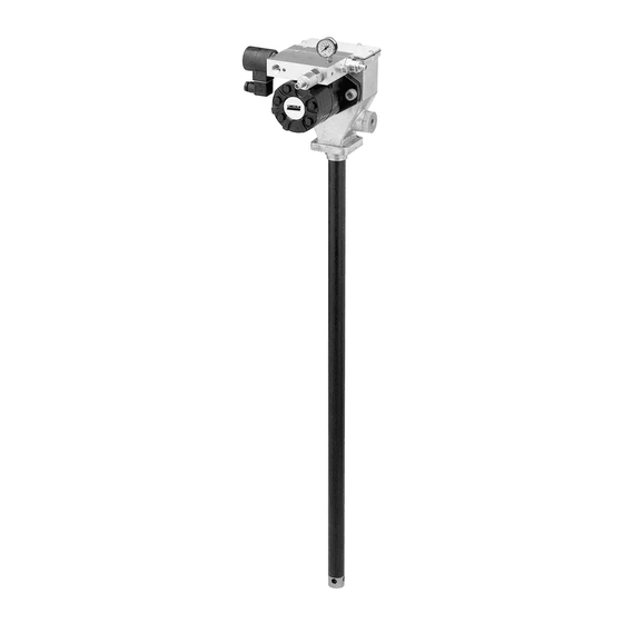
FlowMaster rotary driven hydraulic
pump
Models 85480, 85481, 85482 and 85483, series "C"
Model 274055, series "B"
August 2014
Date of issue
Form number
404593X
Section
C8
Page
269X
To order call 1-800-548-1191 or visit www.partdeal.com - info@partdeal.com
D A N G E R
Read manual prior to installation or use
of this product. Keep manual nearby for
future reference. Failure to follow
instructions and safety precautions may
result in death or serious injury.
Installation and maintenance guide
Advertisement
Table of Contents

Related Manuals for Lincoln FlowMaster C Series


Summary of Contents for Lincoln FlowMaster C Series
- Page 1 Installation and maintenance guide FlowMaster rotary driven hydraulic pump Models 85480, 85481, 85482 and 85483, series “C” Model 274055, series “B” August 2014 Date of issue D A N G E R Form number 404593X Read manual prior to installation or use Section of this product.
-
Page 2: Table Of Contents
Contents Safety Explanation of signal words for safety Read and carefully observe these installation Safety ......instructions before installing/operating/ Explanation of signal words for safety . -
Page 3: Inspection
Description Inspection General description If over pressurizing of the equipment is During the down stroke, the pump cylinder believed to have occurred, contact the fac- A newer version of the FlowMaster pump is extended into the grease. Through the tory authorized warranty and service center was introduced in July of 2008. - Page 4 Fig. 1 Schematic Hydraulic motor (42) Material Hydraulic fluid outlet return to tank Hydraulic fluid inlet Flow control valve (39) Solenoid valve ( 34 and 35) Pressure gauge Pressure reducing (Item 32) valve (38) Vent Valve Fig. 2 Fig. 3 Solenoid valve 24V DC connections No connection to...
-
Page 5: Installing The Pump
Test conducted with Alvania NLGI #2 grease Typical installation is shown only as a guide for selecting and installing system compo- Grease output (in.³/min. [cm³/min.]), nents. Contact your Lincoln 1,000 psi (69 bar) back pressure Hydraulic flow input Industrial representative for assistance Temperature 1 gal./min... -
Page 6: Operation
Operation Setting the pump Crankcase oil service manifold pressure and interval All pumps are factory set at 350 psi (24 bar) flow controls recommendations working inlet hydraulic pressure with a flow rate of 2.5 gal./min. (9.5 l/min). Do not change the settings for the pump until The pressure must first be adjusted to •... -
Page 7: Dimensions
Fig. 5 Dimensions 11.53 in. 9.08 in. (293 mm) (231 mm) 9.55 in. (243 mm) 4.60 in. (117 mm) 3.11 in. (79 mm) 5.03 in. (128 mm) 1 1/4 NPTF Pump Outlets 2 SAE 4 Inlet Port 3 SAE 6 Tank Port 4 1/4 NPTR Orifice fitting for vent valve port 5 Solenoid Valve... -
Page 8: Troubleshooting
Troubleshooting Condition Possible cause Corrective action Pump does not run. No pressure on gauge (72): - Closed Supply line shut off valve. Open shut-off valve. - No power to solenoid valve (73). Correct electrical fault. - Faulty Solenoid (74). Replace solenoid (74). - Pressure Reducing Valve (77) is set too low. -
Page 9: Tools Required For Maintenance Repair And Adjustment
Tools required for Maintenance and W A R N I N G maintenance, repair repair Always use Lincoln Industrial parts for and adjustment Relieve pressure from the pump and supply service and repair. lines before servicing or repairing the pump, •... - Page 10 1 Remove dip stick (Item 30a). (Reassem- 2 Drain crankcase oil (reassembly recom- 3 Remove housing cover screws (Item 28). bly torque: 10 - 15 in. lbs. (1.1 - 1.7 mendations: use SAE 10w30 motor oil (Reassembly torque: 10 - 15 in. lbs. (1.1 Nm).) filled to dipstick mark (15 oz.)).
- Page 11 10 Remove pressure reducing valve (Item 11 Remove orifice fitting (Item 78). (Reas- 12 Remove hydraulic flow control (Item 70). 77). (Reassembly torque: 20 - 25 Ft. sembly torque: 20 - 25 Ft. Lbs. (27.1 - (Reassembly torque: 20 - 25 Ft. Lbs. Lbs.(27.1 - 33.9 Nm).) 33.9 Nm), or enough to seal pipe (27.1 - 33.9 Nm).)
- Page 12 16 Remove shovel plug (Item 58) and spac- 17 17. Push pump element (items 1 er (Item 56b) from housing tube. through 27) out of housing tube with nylon rod and hammer included in tool kit (276275). (Reassembly recommen- dation: replace pump element in hous- ing tube with housing tube slightly loose, then torque housing tube (Item 56a) to pump housing (Item 73) to 20-25 Ft.
- Page 13 18 Pull pump element free of housing. 19 Remove housing tube (Item 56a). (Reas- 20 Exploded view of housing tube (Item sembly Torque: 20 to 25 Ft. Lbs.(27.1 - 56a), spacer (Item 56b) and Shovel Plug 33.9 Nm). (Item 58). 21 Remove bronze bushing (Item 57) 22 Remove oil seal O-ring (Item 53) and 23 Remove wrist pin bushing screws (Item...
- Page 14 27 Remove crankkrod and eccentric as- 28 Loosen wrist pin anchor (Item 13a). (Re- 29 Remove wrist pin anchor (Item 13a). sembly (Items 1-7). assembly torque: 20 - 25 Ft. Lbs. (27.1 (Reassembly recommendations: replace - 33.9 Nm).) O-ring seal (Item 13b), be sure threads on wrist pin anchor (Item 13a) are clean and free of all oil or other fluids.) 31 Loosen...
- Page 15 Series “B” To upgrade series “A” Top of pump Top of pump Spacer 275376 36 Remove cup seal (Item 15) and backup washer (Item 14). (Reassembly recom- mendations: replace cup and seal and backup washer. See detail below for orientation.) 37 Hold outlet pin (Item 8) and plunger 38 38.
- Page 16 43 Remove O-ring (Item 10c). 44 Remove backup washer (Item 10b). 45 View of upper bushing and seals (Items 10-10d). 46 Loosen check seal housing (Item 27) 47 Check seat housing assembly (Item 27) with 3/8 Allen wrench. (Reassembly and associated parts removed. (Reas- torque: 20-25 ft.
- Page 17 Top of Bottom pump of pump 49 49. Remove lower bushing (Item 19a) 50 50. To remove lower plunger, use special from reciprocating tube (Item 20). (Re- tool provided in Tool Kit 276275. assembly recommendations: replace O-ring seal (Item 26.) Remove lower cup (Item 21) from reciprocating tube (Item 20).
- Page 18 59 Place assembly on 2 1/2” dia. steel pipe included in tool kit. 57 With both flat head screws removed, re- 58 Remove inner and outer retaining ring move counterbalance weights (Item 2). (Item 5 and Item 3) from both sides. 60 Drive crank eccentric (Item 6) out of ball 61 Drive ball bearing (Item 7) out of crank 62 Remove O-Ring seal (Item 33) from...
- Page 19 65 And then feed the O-ring (Item 34) un- der the back- up washer, pushing up the final bulge of the O-ring with a blunt rod. 64 Reassembly recommendations: To install the O-ring (Item 34) and backup washer (Item35) most easily, install the backup washer first.
- Page 20 Fig. 1 Hydraulic oil flow vs. pump rotations/min. Rotations/min. = 87.7 (gal./min.) - 3.7 Eingagn (gal./min (l/min)) Durchflussvegelventil ist geoffnet Emptohler Einstellungs deseich Pumpen drehsah (U/min.) At pressure setting of 350 psi (24 bar) To order call 1-800-548-1191 or visit www.partdeal.com - info@partdeal.com...
-
Page 21: Exploded View
Fig. 2 Exploded view 275376 Spacer for A to B conversions only To order call 1-800-548-1191 or visit www.partdeal.com - info@partdeal.com... - Page 22 Fig. 3 Exploded view (Included in 56a) To order call 1-800-548-1191 or visit www.partdeal.com - info@partdeal.com...
- Page 23 Fig. 3 Exploded view To order call 1-800-548-1191 or visit www.partdeal.com - info@partdeal.com...
-
Page 24: Repair Parts
Repair parts for all models Item no. Qty. Description Part no. Item no. Qty. Description Part no. Flat head screw (1/4 x 1-3/4) 270635 O-ring Counter weight 272197 O-ring Retaining ring 270609 Backup washer Crankrod 270665 Hydraulic motor kit (Includes 274054 gasket (69) and 2x o-ring (68)) Retaining ring... - Page 25 Repair parts list (non-common parts) Model Model Model Model Model Model 85247 85480 85481 85482 85483 274055 Item no. Qty. Description (120 lb) (120 lbs) 60 lbs) (400 lbs) (5 gal.) (400 lbs) Plunger link rod 270648 270648 270614 270645 270641 270614 Reciprocating tube...
- Page 26 Kit to convert seris “A” to series “B” pumps Consists of Repair ktis Housing Reciprocating Housing Plunger link Size (see above) cover kit tube kit tube kit rod kit 5 gal 276580 275186, 275187, 275188, 275383 275381 275010 275189 270641 90-120 lbs.
-
Page 27: Warranty
(international number 01-314-679-4200) required. or you may also use our website In no event shall Lincoln be liable for inci- www.lincolnindustrial.com dental or consequential damages. Lincoln’s liability for any claim for loss or damages... - Page 28 ® SKF is a registered trademark of the SKF Group. ® Lincoln is a registered trademark of Lincoln Industrial Corp. © SKF Group 2014 The contents of this publication are the copyright of the publisher and may not be reproduced (even extracts) unless prior written permis- sion is granted.
Need help?
Do you have a question about the FlowMaster C Series and is the answer not in the manual?
Questions and answers