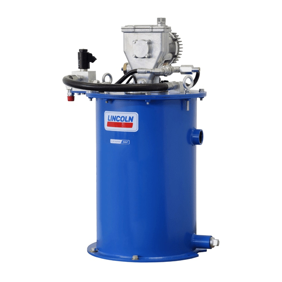
Summary of Contents for Lincoln SKF FlowMaster II A Series
Page 1
User and maintenance instructions FlowMaster II rotary driven V electric pump, series “A” Models and - CAT, US gallons, , lbs, and - CAT, lbs, and - CAT, lbs, , lbs Date of issue August ...
Page 2
Contents Declaration of Conformity* .. U.K. Declaration of Conformity* .. Safety .........
RoHS Directive //EU I, the undersigned of Lincoln Industrial Corporation, do hereby declare that the equipment specified above, in its intended use, conforms to the requirements of the above directives and harmonized standards at the time of placing the above product on the market.
Page 4
:) I, the undersigned of Lincoln Industrial Corporation, hereby declare that the equipment specified above, in its intended use, conforms with all requirements of the U.K. legislation Supply of Machinery (Safety) Regulations No. by the time of placing it on the market.
Safety Explanation of signal WARNING* Do not use equipment to supply, words for safety Read and carefully observe installation transport, or store hazardous instructions before installing, operating or substances and mixtures in accordance troubleshooting assembly. Assembly must with annex I part - of the CLP be installed, maintained and repaired regulation (EG /) or HCS ...
Inspection Overview Description This manual details the procedure that must Lincoln Industrial rotary V If overpressurizing of equipment is believed be followed while installing, operating, electric pump uses a V motor and to have occurred, contact factory authorized...
Page 7
Fig. Pump without controller Item Description V Fuse Manual switch Red wire Motor Black wire Connect red motor lead to the positive side of the circuit. Motor is polarity sensitive and will not run if improperly wired. ...
Page 8
Fig. Pump dimensions 9.13 in (232 mm) 5.84 in 6.97 in (177 mm) (148 mm) 2.72 in (69 mm) / NPTF 1.25 in (32 mm) Dimensions Model Dimension “A” Dimension “B” . in (349 mm) . in (576 mm) ...
Page 9
Install pump Table Install high pressure shut-off valve in mate- rial supply line (required). Electric FlowMaster II pump Pump was tested in lightweight oil and was left in to protect pump from corrosion. Flush V : gear ratio, stage NOTE Backpressure Current...
Crankcase oil service interval Operation NOTE Motor used in V FlowMaster II pump is equipped with a built in speed control. • Check oil level after every hours of Pump speed is factory set to maximum machine operation, or monthly. setting.
Page 11
Disassembly Fig. Refer to Fig. and remove gear box mounting screws (), washers () and gear box (). Loosen and remove screws () holding first Pump stage gear set (), spacer () and final Place pump into vise. stage gear set () in place.
Page 12
Crank rod and eccentric Fig. Insert pin included in tool kit () through tool and into plunger link Remove pivot screws () from rod () outlet hole. crank rod () († fig. ). Turn tool counter clockwise to remove lower bushing and plunger () from plunger link rod ().
Page 13
Reciprocating tube Fig. Loosen check seat housing () with in hex head wrench († fig. ). Remove check seat housing () from reciprocating tube (). Remove ball cage (), check ball () and o-ring seals () from check seat housing ().
Page 14
Pump Assembly Fig. Install ball () into lower bushing and plunger () († fig. ). Crank rod and eccentric Insert check rod () into pump assembly plunger (). Place spring () onto check rod (). Place crank rod () on in (63,5 mm) ...
Page 15
Apply threadlocker to threads of wrist pin Refer to Fig. and insert o-ring () Install retaining ring () on shaft (). bushing screws (). into housing tube (). Install shaft cover () on pump () ...
Page 16
Insert final stage gear set () into Install o-ring () in outlet pin mounting NOTE gear box (). hole groove of pump housing () Refer to Crankcase oil service interval, Install screws () through gear († fig. ). page ...
Troubleshooting Condition Possible cause Corrective action Pump does not run. Pump is seized or damaged. Disassemble pump and repair any parts that are damaged or worn. Incorrectly wired. Connect red motor lead to positive battery terminal and black motor lead to negative terminal.
Need help?
Do you have a question about the SKF FlowMaster II A Series and is the answer not in the manual?
Questions and answers