
Related Manuals for Lincoln SKF FlowMaster II 85727


Summary of Contents for Lincoln SKF FlowMaster II 85727
- Page 1 User and maintenance instructions FlowMaster II rotary driven hydraulic pump Model 85727 and 85727MSO, series “A” 85727MSO model shown Date of issue July 2023 Form number 404560 Version...
-
Page 2: Table Of Contents
Contents Declaration of Incorporation * ..U.K. Declaration of Incorporation* . . . Safety * ......Description. -
Page 3: Declaration Of Incorporation
EN 349: 1993 Safety of machinery. Minimum gaps to I, the undersigned of Lincoln Industrial avoid crushing of parts of the human body Corporation, do hereby declare that the equipment specified above, in its intended use, conforms to the requirements of the above EC Directive(s). -
Page 4: U.k. Declaration Of Incorporation
I, the undersigned of Lincoln Industrial Corporation, hereby declare that the equipment specified above, in its intended use, conforms with the Essential Health and Safety Requirements of U.K. legislation Supply of Machinery (Safety) Regulations 2008 No. 1597 Annex I, Declaration of Incorporation by the time of placing it on the market. -
Page 5: Safety
Safety * Explanation of signal CAUTION words for safety Do not operate equipment without wearing personal protective gear. The assembly must be installed, maintained Wear eye protection. Protective and repaired exclusively by persons familiar equipment such as dust mask, non-skid with the instructions. -
Page 6: Description
Usage Description Operation with Operation with system controller mechanical General description shut-off Models 85727 and 85727MSO are pumping units designed to operate a Centro-Matic Operation with lube system controller is lubrication system. Units includes a vent recommended. System control must be valve to relieve line pressure to recharge capable of operating hydraulic solenoid When attached, a mechanical shut-off sys-... -
Page 7: Dimensions
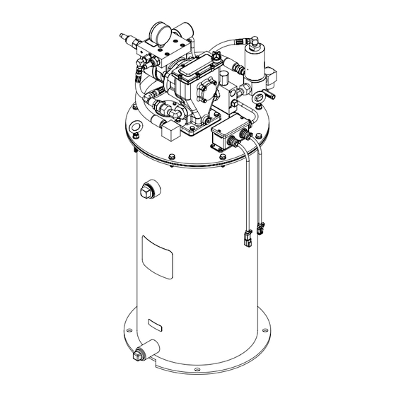
Fig. 1 Dimensions 19 in (483 mm) ∅ 16.7 in (425 mm) ∅ 15.5 in (394 mm) 22 in (559 mm) ∅ 0.60 in (15 mm) 45° 45° 40.8 in (1 036 mm) -
Page 8: Installation
Installation and operation Installation Pump operation Fill reservoir (MSO equipped) Filling reservoir Place unit in approximate location making sure electric and hydraulic power Body and guide assembly (26), pivot arm (25), connections are accessible. To bulk fill reservoir: supply line relief, follower (38) and cover (20) 1 Clean area around filling port. -
Page 9: Maintenance And Repair
Maintenance and repair General maintenance Outlet check service 8 Pull check disk assembly (41) out of ball check seat (42). • Keep area around pump clean. Clean off Refer to Troubleshooting (page 12) to 9 Remove and discard gaskets (39 and 44). filling port area prior to filling reservoir. -
Page 10: Vent Valve Service
Vent valve service Follower Grease level indicator Refer to Troubleshooting (page 12) to If follower foam appears to be damaged or If indicator pin appears to drop prematurely determine if vent valve is cause of failure does not wipe sides of container effectively or water is noticeable on top of follower, (†... -
Page 11: Safety Unloader Valve
Safety unloader valve Safety unloader valve (3) († Fig. 3, page 13) is not serviceable. Replace if malfunction is apparent. Upon reassembly, tighten to 10 ft-lbf (13.5 Nm). Safety unloader valve (3) is set to open at 3 750 to 4 250 psi (258 to 293 bar) lubricant pressure. -
Page 12: Troubleshooting
Troubleshooting Condition Possible cause Corrective action Pump does not operate. No hydraulic power to pump. Turn on or connect hydraulic supply to pump. No pressure on gauge: • Closed supply line shut off valve. Open shut-off valve. • No power to solenoid valve. Correct electrical fault. -
Page 13: Reservoir Cover
Fig. 2 Fig. 3 Reservoir cover Outlet check assembly (11) 42 43 Fig. 5 Low level indicator Fig. 4 Hydraulic vent valve (28) -
Page 14: Follower Assembly (38)
Fig. 6 Follower assembly (38) Stagger long bolts and small bolts on follower plate. Fig. 7 Grease level sensor port... -
Page 15: Conduit Box Assembly (9)
Fig. 8 Conduit box assembly (9) - Page 16 Fig. IPB 1 15 16 Model 85725MSO only...
-
Page 17: Service Parts
Service parts Item Description Quantity Part Item Description Part Quantity Vent hose assembly 270726 Valve body 239336 Supply hose assembly 277441 Indicator bracket (85727) 361020 Safety unloader 90942 Indicator bracket (85727MSO) 361020MSO Reducer nipple 14727 Retaining ring 68888 Elbow 277439 Cable assembly 278018 Vent fitting... -
Page 18: Warranty
® SKF and Lincoln are registered trademarks of the SKF Group. © SKF Group 2023 The contents of this publication are the copyright of the publisher and may not be reproduced (even extracts) unless prior written permission is granted. Every care has been taken to ensure the accuracy of the information contained in this publication but no liability can be accepted for any loss or damage whether direct, indirect or consequential arising out of the use of the information contained herein.
Need help?
Do you have a question about the SKF FlowMaster II 85727 and is the answer not in the manual?
Questions and answers