Table of Contents
Advertisement
Quick Links
Advertisement
Table of Contents

Related Manuals for THORLABS FDPSE2X2


Summary of Contents for THORLABS FDPSE2X2
- Page 1 FDPSE2X2 Lead Selenide Photoconductor User Guide...
-
Page 2: Table Of Contents
Specifications ..............7 4.1. Response Curve ............ 8 4.2. SNR vs. Chopping Frequency ........ 8 4.3. SNR vs. Supply Voltage .......... 9 4.4. Dark Resistance vs. Temperature ........ 9 4.5. Temperature vs. Sensitivity ........ 10 Chapter 5 Mechanical Drawing ............11 Chapter 6 Regulatory ................ 12 Chapter 7 Thorlabs Worldwide Contacts ........13 ... -
Page 3: Chapter 1 Warning Symbol Definitions
PbSe Detector Chapter 1: Warning Symbol Definitions Chapter 1 Warning Symbol Definitions Below is a list of warning symbols you may encounter in this manual or on your device. Symbol Description Direct Current Alternating Current Both Direct and Alternating Current Earth Ground Terminal Protective Conductor Terminal Frame or chassis Terminal... -
Page 4: Chapter 2 Description
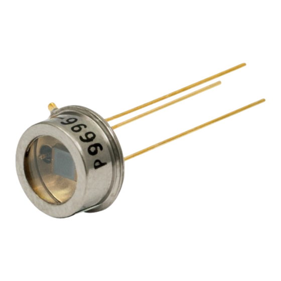
PbSe Detector Chapter 2: Description Chapter 2 Description Thorlabs’ FDPSE2X2 photoconductor is a Lead Selenide Detector (PbSe), which is ideal for measuring both pulse and chopped infrared light sources. The photoconductor is housed conveniently in a TO-5 package, offering easy integration into existing setups and/or systems. -
Page 5: Frequency Response
3.2. Frequency Response Photoconductors must be used with a pulsed signal to obtain AC signals. An optical chopper, such as Thorlabs’ MC2000, is recommended for use with CW light. The detector responsivity (R ) when using a chopper can be calculated... -
Page 6: Temperature Considerations
PbSe Detector Chapter 3: Operation The characteristic curve for Signal vs. Chopping Frequency for this particular detector is provided in Chapter 4. 3.4. Temperature Considerations These detectors consist of a thin film on a glass substrate. The effective shape and active area of the photoconductive surface varies considerably based upon the operating conditions, thus changing performance characteristics. -
Page 7: Detectivity (D) And D
PbSe Detector Chapter 3: Operation Cooling the device will increase the dark resistance. Chapter 4 provides a Dark Resistance vs. Temperature characteristic graph for the particular detector. 3.8. Detectivity (D) and D Detectivity (D) is another criteria used to evaluate the performance of the photodetector. - Page 8 PbSe Detector Chapter 3: Operation Feedback Resistor LOAD C filter R filter Detector Optical RC Filter Chopper Figure 2: Amplifier Model Page 6 24701-D02...
-
Page 9: Chapter 4 Specifications
PbSe Detector Chapter 4: Specifications Chapter 4 Specifications All measurements performed with 25 °C element temperature unless stated otherwise. Electrical Specifications Detector PbSe Active Area 2.0 mm x 2.0 mm (4 mm Wavelength Range λ 1500 to 4800 nm Peak Wavelength λ... -
Page 10: Response Curve
PbSe Detector Chapter 4: Specifications 4.1. Response Curve PbSe Photoconductor Responsivity 3500 3000 2500 2000 1500 1000 Wavelength (μm) 4.2. SNR vs. Chopping Frequency SNR vs. Chopping Frequency Supply Voltage: 15V 1000 Signal Noise 1000 Chopping Frequency (Hz) Page 8 24701-D02... -
Page 11: Snr Vs. Supply Voltage
PbSe Detector Chapter 4: Specifications 4.3. SNR vs. Supply Voltage SNR vs. Supply Voltage Chopping Frequency: 600 Hz, Bandwidth: 60 Hz 1600 Signal Noise 1200 Supply Voltage (V) 4.4. Dark Resistance vs. Temperature Dark Resistance vs. Temperature ‐20 ‐10 Temperature (°C) Rev C, May 25, 2017 Page 9... -
Page 12: Temperature Vs. Sensitivity
PbSe Detector Chapter 4: Specifications 4.5. Temperature vs. Sensitivity Temperature vs. Sensitivity Supply Voltage: 15V, Chopping Freq.: 600Hz 1000 ‐20 ‐10 Temperature (°C) Page 10 24701-D02... -
Page 13: Chapter 5 Mechanical Drawing
PbSe Detector Chapter 5: Mechanical Drawing Chapter 5 Mechanical Drawing Visit the web for a more detailed mechanical drawing. Pin 1 (Detector) Pin 3 (Ground) Ø9.1 mm (Ø0.36") Ø5.1 mm (Ø0.20") Pin 2 (Detector) 2.1 mm 18.0 mm (0.08") (0.35") 2.0 mm (0.08") Ø8.1 mm... -
Page 14: Chapter 6 Regulatory
6.1. Waste Treatment is Your Own Responsibility If you do not return an “end of life” unit to Thorlabs, you must hand it to a company specialized in waste recovery. Do not dispose of the unit in a litter bin or at a public waste disposal site. -
Page 15: Chapter 7 Thorlabs Worldwide Contacts
Chapter 7 Thorlabs Worldwide Contacts For technical support or sales inquiries, please visit us at www.thorlabs.com/contact for our most up-to-date contact information. USA, Canada, and South America UK and Ireland Thorlabs, Inc. Thorlabs Ltd. sales@thorlabs.com sales.uk@thorlabs.com techsupport@thorlabs.com techsupport.uk@thorlabs.com Europe Scandinavia... - Page 16 www.thorlabs.com...
Need help?
Do you have a question about the FDPSE2X2 and is the answer not in the manual?
Questions and answers