
Related Manuals for THORLABS ELL14


Summary of Contents for THORLABS ELL14
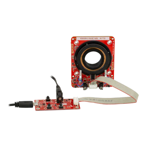
- Page 1 ELL14 Motorized SM1 Optic Rotator ELL14 and ELL14K Motorized SM1 Optics Rotator Kit Operating Manual Original Instructions...
-
Page 2: Table Of Contents
Controlling the Rotator Without the Handset ..................10 Chapter 5 Troubleshooting and FAQ ............................. 13 Chapter 6 Specifications ................................. 17 Chapter 7 Regulatory ................................18 7.1.1 For Customers in Europe ........................18 7.1.2 For Customers in the USA ........................ 18 Chapter 8 Thorlabs Worldwide Contacts ..........................19... -
Page 3: Chapter 1 Introduction
Introduction The ELL14 is part of the Thorlabs series of resonant piezo motor circuits and bare modules for OEM applications. This SM1- threaded Optics Rotator can be adapted to 30 and 60 mm cage systems and can also be adapted for post mounting – see section 3.1 for more details. -
Page 4: Chapter 2 Safety
ELL14 Motorized SM1 Optic Rotator Chapter 2: Safety Chapter 2 Safety For the continuing safety of the operators of this equipment, and the protection of the equipment itself, the operator should take note of the Warnings, Cautions and Notes throughout this handbook and, where visible, on the product itself. -
Page 5: Chapter 3 Description
ELL14 Motorized SM1 Optic Rotator Chapter 3: Description Chapter 3 Description Environmental Conditions Warning Operation outside the following environmental limits may adversely affect operator safety. Location Indoor use only Maximum altitude 2000 m Temperature range 15°C to 40°C Maximum Humidity Less than 80% RH (non-condensing) at 31°C... - Page 6 ELL14 Motorized SM1 Optic Rotator Chapter 3: Description Figure 1 ELL14 Rotation Stage showing its 3 Possible Mounting Hole Patterns The rotator is shipped with two SM1 retaining rings, allowing SM1 optics to be fitted. There are several options for mounting the rotator.
- Page 7 When combined with four SR-series posts, the rotator can be fitted to our ER-series cage rods within a 30 mm cage system. Figure 3 ELL14 Mounted in a 30 mm Cage System If combined with the SR-series posts and the ELLA1 Adapter, the unit can be mounted on our range of Ø1/2" posts or used with SM1-threaded components, such as lens tubes.
-
Page 8: Chapter 4 Operation
ELL14 Motorized SM1 Optic Rotator Chapter 4: Operation Chapter 4 Operation Getting Started Caution Although the module can tolerate up to 8 kV of air discharge, it must be treated as an ESD sensitive device. When handling the device, anti-static precautions must be taken and suitable anti-discharge appliances must be worn. - Page 9 ELL14 Motorized SM1 Optic Rotator Chapter 4: Operation Controlling the Rotator The rotator can be controlled in three ways; via the handset, by the Elliptec software running on a PC, or by writing a custom application using the messages described in the communications protocol document. Homing and Jogging functionality can also be accessed by applying voltages to the digital lines on Connector J1.
-
Page 10: Hand-Held Controller
ELL14 Motorized SM1 Optic Rotator Chapter 4: Operation 4.2.1 Hand-held Controller Caution On power up the rotator will move while the unit checks the sensors and then searches for the home position. The hand-held controller supplied with the ELL14K Evaluation Kit features two buttons (marked FW and BW) that allow control of the rotator position. -
Page 11: Software Control
4.2.2 Software Control When connected to the host PC, the rotator can be controlled remotely, via the Elliptec software. 1. Download the Elliptec software from the downloads section at www.thorlabs.com. Double click the saved .exe file and follow the on-screen instructions. -
Page 12: Communications Protocol
ELL14 Motorized SM1 Optic Rotator Chapter 4: Operation 4.2.3 Communications Protocol Custom move applications can be written in languages such as C# and C++. The communication bus allows multi-drop communication with speeds at 9600 baud, 8 bit data length, 1 stop bit, no parity. - Page 13 ELL14 Motorized SM1 Optic Rotator Chapter 4: Operation Connector J1 Pin Out TYPE FUNCTION Ground ODTX - open drain transmit 3.3V TTL RS232 RX receive - 3.3V TTL RS232 In Motion, open drain active low max 5mA JOG/Mode, active low max 5V...
- Page 14 ELL14 Motorized SM1 Optic Rotator Chapter 4: Operation Frequency Search Due to load, build tolerances and other mechanical variances, the default resonating frequency of a particular motor may not be that which delivers best performance. A frequency search can be performed using the Main GUI Settings panel in the ELLO software, or by using the serial communication line (SEARCHFREQ_MOTORX message), which offers a way to optimize the operating frequencies for backward and forward movement.
-
Page 15: Chapter 5 Troubleshooting And Faq
ELL14 Motorized SM1 Optic Rotator Chapter 5: Troubleshooting and FAQ Chapter 5 Troubleshooting and FAQ Frequently Asked Questions Rotator not moving Check power supply lines ratings (polarity, voltage drop or range, available current) or reduce cable length. Check module is not in boot loader mode (power cycle the module to exit boot loader). Current consumption must be higher than 36 mA at 5 V. - Page 16 What is the typical product life time? ELL14 product life time is restricted by the wearing of moving surfaces and the motor contact as motion is started (due to resonance build up) and performed (due to friction), and is expressed in km travelled. Lifetime will depend on several factors (e.g.
- Page 17 ELL14 Motorized SM1 Optic Rotator Chapter 5: Troubleshooting and FAQ Notes on Making a Picoflex Cable for Use when Daisy Chaining Devices The multi-drop communications bus offers the option of connecting the stage to a hybrid network of up to 16 Elliptec resonant motor products and controlling the connected units with a device such as a microprocessor.
- Page 18 ELL14 Motorized SM1 Optic Rotator Chapter 5: Troubleshooting and FAQ Using a screwdriver or other suitable tool, push down the crimp of each pin to make connection with the ribbon cable. If other connectors are required they should be fitted at this point. Slide each connector onto the cable, paying attention to the orientation as shown below, then crimp as detailed in step (3).
-
Page 19: Chapter 6 Specifications
ELL14 Motorized SM1 Optic Rotator Chapter 6: Specifications Chapter 6 Specifications General Specifications Travel 720° Minimum Life Time 100 km (>600,000 revolutions) Max Speed 430 °/s Bidirectional Repeatability 0.05 ° Homing Repeatability 0.25 ° Bidirectional Accuracy 0.4 ° Backlash 0.013 °... -
Page 20: Chapter 7 Regulatory
ELL14 Motorized SM1 Optic Rotator Chapter 7: Regulatory Chapter 7 Regulatory Declarations of Conformity 7.1.1 For Customers in Europe 7.1.2 For Customers in the USA This equipment has been tested and found to comply with the limits for a Class A digital device, pursuant to part 15 of the FCC rules. -
Page 21: Chapter 8 Thorlabs Worldwide Contacts
Contact Thorlabs for more information. Waste treatment is your own responsibility. “End of life” units must be returned to Thorlabs or handed to a company specializing in waste recovery. Do not dispose of the unit in a litter bin or at a public waste disposal site. - Page 22 www.thorlabs.com...
Need help?
Do you have a question about the ELL14 and is the answer not in the manual?
Questions and answers