ZyXEL Communications Dimension GS-2024 User Manual
Hide thumbs
Also See for Dimension GS-2024:
- User manual (266 pages) ,
- Quick start manual (43 pages) ,
- Specifications (4 pages)
Table of Contents
Advertisement
Quick Links
Advertisement
Chapters
Table of Contents
Troubleshooting

Related Manuals for ZyXEL Communications Dimension GS-2024


Summary of Contents for ZyXEL Communications Dimension GS-2024
- Page 1 Dimension GS-2024 Gigabit Ethernet switch User’s Guide Version 3.60 8/2005...
-
Page 3: Copyright
Published by ZyXEL Communications Corporation. All rights reserved. Disclaimer ZyXEL does not assume any liability arising out of the application or use of any products, or software described herein. Neither does it convey any license under its patent rights nor the patent rights of others. -
Page 4: Interference Statements And Warnings
GS-2024 User’s Guide Interference Statements and Warnings FCC Statement This switch complies with Part 15 of the FCC rules. Operation is subject to the following two conditions: 1 This switch may not cause harmful interference. 2 This switch must accept any interference received, including interference that may cause undesired operations. -
Page 5: Safety Warnings
GS-2024 User’s Guide 2 Select your product from the drop-down list box on the ZyXEL home page to go to that product's page. 3 Select the certification you wish to view from this page. Registration Register your product online for free future product updates and information at www.zyxel.com for global products, or at www.us.zyxel.com for North American products. -
Page 6: Zyxel Limited Warranty
Any returned products without proof of purchase or those with an out-dated warranty will be repaired or replaced (at the discretion of ZyXEL) and the customer will be billed for parts and labor. All repaired or replaced products will be shipped by ZyXEL to the corresponding return address, Postage Paid. -
Page 7: Customer Support
GS-2024 User’s Guide Customer Support Please have the following information ready when you contact customer support. • Product model and serial number. • Warranty Information. • Date that you received your device. • Brief description of the problem and the steps you took to solve it. - Page 8 GS-2024 User’s Guide METHOD SUPPORT E-MAIL TELEPHONE* WEB SITE REGULAR MAIL SALES E-MAIL FTP SITE LOCATION support@zyxel.co.uk +44 (0) 8702 909090 www.zyxel.co.uk ZyXEL Communications UK Ltd.,11, The Courtyard, sales@zyxel.co.uk +44 (0) 1344 303044 ftp.zyxel.co.uk Eastern Road, Bracknell, UNITED KINGDOM Berkshire, RG12 2XB,...
-
Page 9: Table Of Contents
GS-2024 User’s Guide Table of Contents Copyright ........................1 Interference Statements and Warnings ..............2 ZyXEL Limited Warranty..................4 Customer Support....................5 Preface ........................25 Chapter 1 Getting to Know Your Switch ................27 1.1 Introduction ......................27 1.2 Software Features ....................27 1.3 Hardware Features ....................29... - Page 10 GS-2024 User’s Guide 3.1.2.1 Default Ethernet Settings ..............40 3.1.3 Mini-GBIC Slots ..................40 3.1.3.1 Transceiver Installation ..............41 3.1.3.2 Transceiver Removal ..............41 3.2 Rear Panel ......................42 3.2.1 Power Connector ..................42 3.3 Front Panel LEDs ...................43 Chapter 4 The Web Configurator.................... 45 4.1 Introduction ......................45 4.2 System Login...
- Page 11 GS-2024 User’s Guide Chapter 8 VLAN ........................75 8.1 Introduction to IEEE 802.1Q Tagged VLAN ............75 8.1.1 Forwarding Tagged and Untagged Frames ..........75 8.2 Automatic VLAN Registration ................76 8.2.1 GARP .......................76 8.2.1.1 GARP Timers .................76 8.2.2 GVRP ......................76 8.3 Port VLAN Trunking ..................77...
- Page 12 GS-2024 User’s Guide 13.2 Port Mirroring Setup ..................105 Chapter 14 Link Aggregation....................107 14.1 Overview ......................107 14.2 Dynamic Link Aggregation ................107 14.2.1 Link Aggregation ID ................108 14.3 Link Aggregation Status ................108 14.4 Link Aggregation Setup .................109 Chapter 15 Port Authentication ....................113 15.1 Overview ......................113...
- Page 13 GS-2024 User’s Guide 18.6 General MVR Configuration ................129 18.7 MVR Group Configuration ................131 18.7.1 MVR Configuration Example ..............133 Chapter 19 Static Route ......................137 19.1 Configuring ....................137 Chapter 20 Differentiated Services ..................139 20.1 Overview ......................139 20.1.1 DSCP and Per-Hop Behavior ..............139 20.1.2 DiffServ Network Example ..............139...
- Page 14 GS-2024 User’s Guide 22.6.1 Requirements for Using SSH ..............156 22.7 Introduction to HTTPS ..................156 22.8 HTTPS Example ....................157 22.8.1 Internet Explorer Warning Messages ...........157 22.8.2 Netscape Navigator Warning Messages ..........157 22.8.3 The Main Screen ..................158 22.9 Service Port Access Control ................160...
- Page 15 GS-2024 User’s Guide 27.5 Getting Help ....................178 27.5.1 List of Available Commands ..............178 27.5.2 Detailed Command Information ............179 27.6 Command Modes ...................179 27.7 Using Command History ................180 27.8 Saving Your Configuration ................180 27.8.1 Logging Out ..................181 27.9 Command Summary ..................181 27.9.1 User Mode ....................181...
- Page 16 GS-2024 User’s Guide 28.8.7 queuing-method spq ................212 28.8.8 queuing-method wrr ................212 28.8.9 egress set ....................213 28.8.10 qos priority ..................213 28.8.11 name ....................214 28.8.12 speed-duplex ..................214 Chapter 29 IEEE 802.1Q Tagged VLAN Commands ............. 217 29.1 IEEE 802.1Q Tagged VLAN Overview ............217 29.2 VLAN Databases ....................217...
- Page 17 GS-2024 User’s Guide Product Specifications ..................237 Appendix B IP Subnetting ......................241 Index........................249...
- Page 18 GS-2024 User’s Guide...
- Page 19 GS-2024 User’s Guide List of Figures Figure 1 Backbone Application ..................30 Figure 2 Bridging Application .................... 31 Figure 3 High Performance Switched Application .............. 31 Figure 4 Tag-based VLAN Application ................32 Figure 5 Shared Server Using VLAN Example ..............33 Figure 6 Attaching Rubber Feet ..................
- Page 20 GS-2024 User’s Guide Figure 37 Static MAC Forwarding ..................88 Figure 38 Spanning Tree Protocol: Status ................93 Figure 39 Spanning Tree Protocol: Configuration .............. 95 Figure 40 Bandwidth Control ....................98 Figure 41 Broadcast Storm Control ..................102 Figure 42 Mirroring ......................105 Figure 43 Link Aggregation Control Protocol Status ............
- Page 21 GS-2024 User’s Guide Figure 80 HTTPS Implementation ..................156 Figure 81 Security Alert Dialog Box (Internet Explorer) ............157 Figure 82 Security Certificate 1 (Netscape) ................ 158 Figure 83 Security Certificate 2 (Netscape) ................ 158 Figure 84 Login Screen (Internet Explorer) ................. 159 Figure 85 Login Screen (Netscape) ..................
- Page 22 GS-2024 User’s Guide Figure 123 mirror Command Example ................210 Figure 124 gvrp Command Example ................. 211 Figure 125 ingress-check Command Example ..............211 Figure 126 frame-type Command Example ............... 212 Figure 127 queuing-method spq Command Example ............212 Figure 128 queuing-method wrr Command Example ............213 Figure 129 egress set Command Example ................
- Page 23 GS-2024 User’s Guide List of Tables Table 1 Front Panel ......................39 Table 2 Front Panel LEDs ....................43 Table 3 Navigation Panel Sub-links Overview ..............47 Table 4 Web Configurator Screen Sub-links Details ............47 Table 5 Navigation Panel Links ..................48 Table 6 Status ........................
- Page 24 Table 49 Access Control: Service Access Control ............. 161 Table 50 Access Control: Remote Management ..............162 Table 51 Diagnostic ......................163 Table 52 ZyXEL Clustering Management Specifications ............ 165 Table 53 Cluster Management: Status ................166 Table 54 FTP Upload to Cluster Member Example ............168 Table 55 Clustering Management Configuration ..............
- Page 25 GS-2024 User’s Guide Table 80 Subnet 4 ......................246 Table 81 Eight Subnets ...................... 246 Table 82 Class C Subnet Planning ..................246 Table 83 Class B Subnet Planning ..................247...
- Page 26 GS-2024 User’s Guide...
-
Page 27: Preface
Settings and then click Control Panel. • “e.g.,” is a shorthand for “for instance”, and “i.e.,” means “that is” or “in other words”. • The GS-2024 Gigabite Ethernet Switch may be referred to as “the GS-2024” or “the switch” in this User’s Guide. -
Page 28: User Guide Feedback
User Guide Feedback Help us help you. E-mail all User Guide-related comments, questions or suggestions for improvement to techwriters@zyxel.com.tw or send regular mail to The Technical Writing Team, ZyXEL Communications Corp., 6 Innovation Road II, Science-Based Industrial Park, Hsinchu, 300, Taiwan. Thank you. -
Page 29: Getting To Know Your Switch
This chapter introduces the main features and applications of the switch. 1.1 Introduction The GS-2024 is a stand-alone layer-2 Gigabit Ethernet switch with 24 100/1000Mbps ports and two mini-GBIC (Gigabit Interface Converter) slots for optical uplinking and one console port and RJ-45 port for local management. -
Page 30: Port Mirroring
GS-2024 User’s Guide Queuing Queuing is used to help solve performance degradation when there is network congestion. Two scheduling services are supported: Strict Priority Queuing (SPQ) and Weighted Round Robin Scheduling (WRR). This allows the switch to maintain separate queues for packets from each individual source or flow and prevent a source from monopolizing the bandwidth. -
Page 31: Hardware Features
GS-2024 User’s Guide Port Authentication and Security For security, the switch allows authentication using IEEE 802.1x with an external RADIUS server and port security that allows only packets with dynamically learned MAC addresses and/or configured static MAC addresses to pass through a port on the switch. -
Page 32: Applications
GS-2024 User’s Guide Fans The fans cool the switch sufficiently to allow reliable operation of the switch in even poorly ventilated rooms or basements. 1.4 Applications This section shows a few examples of using the switch in various network environments. -
Page 33: High Performance Switched Example
GS-2024 User’s Guide Figure 2 Bridging Application 1.4.3 High Performance Switched Example The switch is ideal for connecting two networks that need high bandwidth. In the following example, use trunking to connect these two networks. Switching to higher-speed LANs such as ATM (Asynchronous Transmission Mode) is not feasible for most people due to the expense of replacing all existing Ethernet cables and adapter cards, restructuring your network and complex maintenance. -
Page 34: Tag-Based Vlan Example
GS-2024 User’s Guide A VLAN (Virtual Local Area Network) allows a physical network to be partitioned into multiple logical networks. Stations on a logical network belong to one group. A station can belong to more than one group. With VLAN, a station cannot directly talk to or hear from stations that are not in the same group(s) unless such traffic first goes through a router. -
Page 35: Figure 5 Shared Server Using Vlan Example
GS-2024 User’s Guide Figure 5 Shared Server Using VLAN Example Chapter 1 Getting to Know Your Switch... - Page 36 GS-2024 User’s Guide Chapter 1 Getting to Know Your Switch...
-
Page 37: Hardware Installation And Connection
GS-2024 User’s Guide H A P T E R Hardware Installation and Connection This chapter shows you how to install and connect the switch. 2.1 Freestanding Installation 1 Make sure the switch is clean and dry. 2 Set the switch on a smooth, level surface strong enough to support the weight of the switch and the connected cables. -
Page 38: Mounting The Switch On A Rack
GS-2024 User’s Guide 2.2 Mounting the Switch on a Rack This section lists the rack mounting requirements and precautions and describes the installation steps. 2.2.1 Rack-mounted Installation Requirements • Two mounting brackets. • Eight M3 flat head screws and a #2 Philips screwdriver. -
Page 39: Figure 8 Mounting The Switch On A Rack
GS-2024 User’s Guide Figure 8 Mounting the Switch on a Rack 2 Using a #2 Philips screwdriver, install the M5 flat head screws through the mounting bracket holes into the rack. 3 Repeat steps to attach the second mounting bracket on the other side of the rack. - Page 40 GS-2024 User’s Guide Chapter 2 Hardware Installation and Connection...
-
Page 41: Chapter 3 Hardware Overview
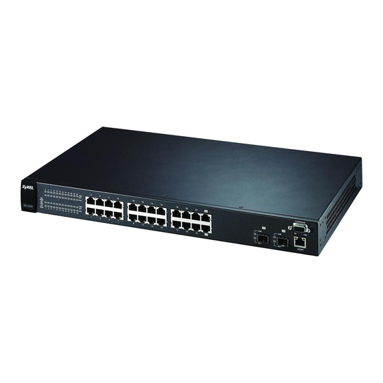
GS-2024 User’s Guide H A P T E R Hardware Overview This chapter describes the front panel and rear panel of the switch and shows you how to make the hardware connections. 3.1 Front Panel Connection The figure below shows the front panel of the switch. -
Page 42: Ethernet Ports
GS-2024 User’s Guide • No parity, 8 data bits, 1 stop bit • No flow control Connect the male 9-pin end of the console cable to the console port of the switch. Connect the female end to a serial port (COM1, COM2 or other COM port) of your computer. -
Page 43: Transceiver Installation
GS-2024 User’s Guide • Type: SFP connection interface • Connection speed: 1 Gigabit per second (Gbps) Note: To avoid possible eye injury, do not look into an operating fiber-optic module’s connectors. 3.1.3.1 Transceiver Installation Use the following steps to install a mini GBIC transceiver (SFP module). -
Page 44: Rear Panel
GS-2024 User’s Guide Figure 12 Opening the Transceiver’s Latch Example 2 Pull the transceiver out of the slot. Figure 13 Transceiver Removal Example 3.2 Rear Panel The following figure shows the rear panel of the switch. The power receptacle is on the read panel. -
Page 45: Front Panel Leds
GS-2024 User’s Guide To connect the power to the switch, insert the female end of power cord to the power receptacle on the rear panel. Connect the other end of the supplied power cord to the power source. Make sure that no objects obstruct the airflow of the fans. - Page 46 GS-2024 User’s Guide Chapter 3 Hardware Overview...
-
Page 47: The Web Configurator
GS-2024 User’s Guide H A P T E R The Web Configurator This section introduces the configuration and functions of the web configurator. 4.1 Introduction The web configurator is an HTML-based management interface that allows easy switch setup and management via Internet browser. Use Internet Explorer 6.0 and later or Netscape Navigator 7.0 and later versions. -
Page 48: The Status Screen
GS-2024 User’s Guide 4 Click OK to view the first web configurator screen. 4.3 The Status Screen The Status screen is the first screen that displays when you access the web configurator. The following figure shows the navigating components of a web configurator screen. -
Page 49: Table 3 Navigation Panel Sub-Links Overview
GS-2024 User’s Guide Table 3 Navigation Panel Sub-links Overview BASIC SETTING ADVANCED APPLICATION IP APPLICATION MANAGEMENT The following table lists the various web configurator screens within the sub-links. Table 4 Web Configurator Screen Sub-links Details ADVANCED BASIC SETTING IP APPLICATION... -
Page 50: Table 5 Navigation Panel Links
GS-2024 User’s Guide Table 4 Web Configurator Screen Sub-links Details (continued) ADVANCED BASIC SETTING IP APPLICATION MANAGEMENT APPLICATION Port Authentication MAC Table RADIUS ARP Table 802.1x Port Security Queuing Method Multicast Multicast Status Multicast Setting IGMP Filtering Profile The following table describes the links in the navigation panel. -
Page 51: Change Your Password
GS-2024 User’s Guide Table 5 Navigation Panel Links (continued) LINK DESCRIPTION Link Aggregation This link takes you to a screen where you can logically aggregate physical links to form one logical, higher-bandwidth link. Port This link takes you to a screen where you can configure RADIUS (Remote... -
Page 52: Switch Lockout
GS-2024 User’s Guide Figure 17 Change Administrator Login Password 4.4 Switch Lockout You could block yourself (and all others) from accessing the switch through the web configurator if you do one of the following: 1 Deleting the management VLAN (default is VLAN 1). -
Page 53: Resetting The Switch
GS-2024 User’s Guide 4.5 Resetting the Switch If you lock yourself (and others) from the switch or forget the switch password, you will need to reload the factory-default configuration file or reset the switch back to the factory defaults. 4.5.1 Reload the Configuration File Uploading the factory-default configuration file replaces the current configuration file with the factory-default configuration file. -
Page 54: Logging Out Of The Web Configurator
GS-2024 User’s Guide Figure 18 Resetting the Switch: Via the Console Port Bootbase Version: V0.6 | 05/18/2004 15:28:28 AM:Size = 32 Mbytes DRAM POST: Testing: 32768K OK DRAM Test SUCCESS ! FLASH: Intel 32M ZyNOS Version: V3.60(LT.0)b3 | 06/21/2005 17:00:44 Press any key to enter debug mode within 3 seconds. -
Page 55: Initial Setup Example
GS-2024 User’s Guide H A P T E R Initial Setup Example This chapter shows how to set up the switch for an example network. 5.1 Overview The following lists the configuration steps for the initial setup: • Create a VLAN •... -
Page 56: Setting Port Vid
GS-2024 User’s Guide 1 Click Advanced Application and VLAN in the navigation panel and click the Static VLAN link. 2 In the Static VLAN screen, select ACTIVE, enter a descriptive name in the Name field and enter 2 in the VLAN Group ID field for the VLAN2 network. -
Page 57: Configuring Switch Management Ip Address
GS-2024 User’s Guide In the example network, configure 2 as the port VID on port 10 so that any untagged frames received on that port get sent to VLAN 2. Figure 21 Initial Setup Network Example: Port VID 1 Click Advanced Applications and VLAN in the navigation panel. -
Page 58: Figure 22 Initial Setup Example: Management Ip Address
GS-2024 User’s Guide Figure 22 Initial Setup Example: Management IP Address 1 Connect your computer to any Ethernet port on the switch. Make sure your computer is in the same subnet as the switch. 2 Open your web browser and enter 192.168.1.1 (the default IP address) in the address bar to access the web configurator. -
Page 59: System Status And Port Statistics
GS-2024 User’s Guide H A P T E R System Status and Port Statistics This chapter describes the system status (web configurator home page) and port details screens. 6.1 Overview The status screen of the web configurator displays a port statistical summary table with links to each port showing statistical details. -
Page 60: Figure 23 Status
GS-2024 User’s Guide Figure 23 Status The following table describes the labels in this screen. Table 6 Status LABEL DESCRIPTION System up Time This field shows how long the system has been running since the last time it was started. -
Page 61: Status: Port Details
GS-2024 User’s Guide Table 6 Status (continued) LABEL DESCRIPTION Tx KB/s This field shows the number of kilobytes per second transmitted on this port. Rx KB/s This field shows the number of kilobytes per second received on this port. Up Time This field shows the total amount of time in hours, minutes and seconds the port has been up. -
Page 62: Figure 24 Status: Port Details
GS-2024 User’s Guide Figure 24 Status: Port Details The following table describes the labels in this screen. Table 7 Status: Port Details LABEL DESCRIPTION Port Info Port NO. This field identifies the Ethernet port described in this screen. Link This field shows whether the Ethernet connection is down, and the speed/duplex mode. - Page 63 GS-2024 User’s Guide Table 7 Status: Port Details (continued) LABEL DESCRIPTION TxPkts This field shows the number of transmitted frames on this port RxPkts This field shows the number of received frames on this port Errors This field shows the number of received errors on this port.
- Page 64 GS-2024 User’s Guide Table 7 Status: Port Details (continued) LABEL DESCRIPTION 65-127 This field shows the number of packets (including bad packets) received that were between 65 and 127 octets in length. 128-255 This field shows the number of packets (including bad packets) received that were between 128 and 255 octets in length.
-
Page 65: Chapter 7 Basic Setting
GS-2024 User’s Guide H A P T E R Basic Setting This chapter describes how to configure the System Info, General Setup, Switch Setup, IP Setup and Port Setup screens. 7.1 Overview The System Info screen displays general switch information (such as firmware version number) and hardware polling information (such as fan speeds). -
Page 66: Figure 25 System Info
GS-2024 User’s Guide Figure 25 System Info The following table describes the labels in this screen. Table 8 System Info LABEL DESCRIPTION System Name This field displays the descriptive name of the switch for identification purposes. ZyNOS F/W This field displays the version number of the switch's current firmware including the Version date created. -
Page 67: General Setup
GS-2024 User’s Guide Table 8 System Info (continued) LABEL DESCRIPTION Fan speed A properly functioning fan is an essential component (along with a sufficiently (RPM) ventilated, cool operating environment) in order for the device to stay within the temperature threshold. Each fan has a sensor that is capable of detecting and reporting if the fan speed falls below the threshold shown. -
Page 68: Figure 26 General Setup
GS-2024 User’s Guide Figure 26 General Setup The following table describes the labels in this screen. Table 9 General Setup LABEL DESCRIPTION System Name Choose a descriptive name for identification purposes. This name consists of up to 32 printable characters; spaces are not allowed. -
Page 69: Introduction To Vlans
GS-2024 User’s Guide Table 9 General Setup (continued) LABEL DESCRIPTION Use Time Server Enter the time service protocol that a timeserver sends when you turn on the switch. when Bootup Not all time servers support all protocols, so you may have to use trial and error to find a protocol that works. -
Page 70: Switch Setup Screen
GS-2024 User’s Guide Chapter 8 on page 75 for information on port-based and 802.1Q tagged VLANs. 7.5 Switch Setup Screen Click Basic Setting and then Switch Setup in the navigation panel to display the screen as shown. The VLAN setup screens change depending on whether you choose 802.1Q or Port Based in the VLAN Type field in this screen. -
Page 71: Ip Setup
GS-2024 User’s Guide Table 10 Switch Setup (continued) LABEL DESCRIPTION Join Timer Join Timer sets the duration of the Join Period timer for GVRP in milliseconds. Each port has a Join Period timer. The allowed Join Time range is between 100 and 65535 milliseconds;... -
Page 72: Figure 28 Ip Setup
GS-2024 User’s Guide You can configure up to 64 IP addresses which are used to access and manage the switch from the ports belonging to the pre-defined VLAN(s). Note: You must configure a VLAN first. Figure 28 IP Setup Chapter 7 Basic Setting... -
Page 73: Table 11 Ip Setup
GS-2024 User’s Guide The following table describes the labels in this screen. Table 11 IP Setup LABEL DESCRIPTION Domain DNS (Domain Name System) is for mapping a domain name to its corresponding IP Name Server address and vice versa. Enter a domain name server IP address in order to be able to use a domain name instead of an IP address. -
Page 74: Port Setup
GS-2024 User’s Guide Table 11 IP Setup (continued) LABEL DESCRIPTION Type the VLAN group identification number. Default Enter the IP address of the default outgoing gateway in dotted decimal notation. Gateway Click Add to save the new rule to the switch. It then displays in the summary table at the bottom of the screen. -
Page 75: Figure 29 Port Setup
GS-2024 User’s Guide Figure 29 Port Setup The following table describes the labels in this screen. Table 12 Port Setup LABEL DESCRIPTION Port This is the port index number. Active Select this check box to enable a port. The factory default for all ports is enabled. A port must be enabled for data transmission to occur. - Page 76 GS-2024 User’s Guide Table 12 Port Setup (continued) LABEL DESCRIPTION Speed/Duplex Select the speed and the duplex mode of the connection on this port. Choices are Auto, 10M/Half Duplex, 10M/Full Duplex, 100M/Half Duplex, 100M/ Full Duplex or 1000M/Full Duplex. Selecting Auto (auto-negotiation) allows one port to negotiate with a peer port automatically to obtain the connection speed and duplex mode that both ends support.
-
Page 77: Chapter 8 Vlan
GS-2024 User’s Guide H A P T E R VLAN The type of screen you see here depends on the VLAN Type you selected in the Switch Setup screen. This chapter shows you how to configure 802.1Q tagged and port-based VLANs. -
Page 78: Automatic Vlan Registration
GS-2024 User’s Guide 8.2 Automatic VLAN Registration GARP and GVRP are the protocols used to automatically register VLAN membership across switches. 8.2.1 GARP GARP (Generic Attribute Registration Protocol) allows network switches to register and de- register attribute values with other GARP participants within a bridged LAN. GARP is a protocol that provides a generic mechanism for protocols that serve a more specific application, for example, GVRP. -
Page 79: Port Vlan Trunking
GS-2024 User’s Guide Table 13 IEEE 802.1Q VLAN Terminology (continued) VLAN PARAMETER TERM DESCRIPTION VLAN Port Port VID This is the VLAN ID assigned to untagged frames that this port received. Acceptable frame You may choose to accept both tagged and untagged... -
Page 80: Static Vlan
GS-2024 User’s Guide Figure 31 Switch Setup: Select VLAN Type 8.5 Static VLAN Use a static VLAN to decide whether an incoming frame on a port should be • sent to a VLAN group as normal depends on its VLAN tag. -
Page 81: Configure A Static Vlan
GS-2024 User’s Guide The following table describes the labels in this screen. Table 14 VLAN: VLAN Status LABEL DESCRIPTION The Number of This is the number of VLANs configured on the switch. VLAN Index This is the VLAN index number. -
Page 82: Figure 33 Vlan: Static Vlan
GS-2024 User’s Guide Figure 33 VLAN: Static VLAN Chapter 8 VLAN... -
Page 83: Configure Vlan Port Settings
GS-2024 User’s Guide The following table describes the related labels in this screen. Table 15 VLAN: Static VLAN LABEL DESCRIPTION ACTIVE Select this check box to activate the VLAN settings. Name Enter a descriptive name for the VLAN group for identification purposes. -
Page 84: Figure 34 Vlan: Vlan Port Setting
GS-2024 User’s Guide Figure 34 VLAN: VLAN Port Setting The following table describes the labels in this screen. Table 16 VLAN: VLAN Port Setting LABEL DESCRIPTION GVRP GVRP (GARP VLAN Registration Protocol) is a registration protocol that defines a way for switches to register necessary VLAN members on ports across the network. -
Page 85: Port-Based Vlan Setup
GS-2024 User’s Guide Table 16 VLAN: VLAN Port Setting (continued) LABEL DESCRIPTION Acceptable Frame Specify the type of frames allowed on a port. Choices are All, Tag Only and Untag Type Only. Select All from the drop-down list box to accept all untagged or tagged frames on this port. -
Page 86: Figure 35 Port Based Vlan Setup (All Connected)
GS-2024 User’s Guide Figure 35 Port Based VLAN Setup (All Connected) Chapter 8 VLAN... -
Page 87: Figure 36 Port Based Vlan Setup (Port Isolation)
GS-2024 User’s Guide Figure 36 Port Based VLAN Setup (Port Isolation) The following table describes the labels in this screen. Table 17 Port Based VLAN Setup LABEL DESCRIPTION Setting Wizard Choose All connected or Port isolation. All connected means all ports can communicate with each other, that is, there are no virtual LANs. - Page 88 GS-2024 User’s Guide Table 17 Port Based VLAN Setup (continued) LABEL DESCRIPTION Outgoing These are the egress ports; an egress port is an outgoing port, that is, a port through which a data packet leaves. If you wish to allow two subscriber ports to talk to each other, you must define the egress port for both ports.
-
Page 89: Static Mac Forwarding
GS-2024 User’s Guide H A P T E R Static MAC Forwarding Use these screens to configure static MAC address forwarding. 9.1 Overview A static MAC address entry is an address that has been manually entered in the MAC address learning table. -
Page 90: Figure 37 Static Mac Forwarding
GS-2024 User’s Guide Figure 37 Static MAC Forwarding The following table describes the labels in this screen. Table 18 Static MAC Forwarding LABEL DESCRIPTION Active Select this check box to activate your rule. You may temporarily deactivate a rule without deleting it by clearing this check box. - Page 91 GS-2024 User’s Guide Table 18 Static MAC Forwarding (continued) LABEL DESCRIPTION Delete Click Delete to remove the selected entry from the summary table. Cancel Click Cancel to clear the Delete check boxes. Chapter 9 Static MAC Forwarding...
- Page 92 GS-2024 User’s Guide Chapter 9 Static MAC Forwarding...
-
Page 93: Chapter 10 Spanning Tree Protocol
GS-2024 User’s Guide H A P T E R Spanning Tree Protocol This chapter introduces the Spanning Tree Protocol (STP). 10.1 Overview STP detects and breaks network loops and provides backup links between switches, bridges or routers. It allows a switch to interact with other STP-compliant switches in your network to ensure that only one route exists between any two stations on the network. -
Page 94: How Stp Works
GS-2024 User’s Guide 10.1.2 How STP Works After a bridge determines the lowest cost-spanning tree with STP, it enables the root port and the ports that are the designated ports for connected LANs, and disables all other ports that participate in STP. Network packets are therefore only forwarded between enabled ports, eliminating any possible network loops. -
Page 95: Figure 38 Spanning Tree Protocol: Status
GS-2024 User’s Guide Figure 38 Spanning Tree Protocol: Status The following table describes the labels in this screen. Table 21 Spanning Tree Protocol: Status LABEL DESCRIPTION Spanning Tree This field displays Running if STP is activated. Otherwise, it displays Down. -
Page 96: Configure Stp
GS-2024 User’s Guide Table 21 Spanning Tree Protocol: Status (continued) LABEL DESCRIPTION Polling Interval The text box displays how often (in seconds) this screen refreshes. You may change the refresh interval by typing a new number in the text box and then clicking Set Interval. -
Page 97: Figure 39 Spanning Tree Protocol: Configuration
GS-2024 User’s Guide Figure 39 Spanning Tree Protocol: Configuration Chapter 10 Spanning Tree Protocol... -
Page 98: Table 22 Spanning Tree Protocol: Configuration
GS-2024 User’s Guide The following table describes the labels in this screen. Table 22 Spanning Tree Protocol: Configuration LABEL DESCRIPTION Status Click Status to display the Spanning Tree Protocol Status screen (see Figure 38 on page 93). Active Select this check box to activate STP. Clear this checkbox to disable STP. -
Page 99: Chapter 11 Bandwidth Control
GS-2024 User’s Guide H A P T E R Bandwidth Control This chapter shows you how you can cap the maximum bandwidth using the Bandwidth Control screen. 11.1 Bandwidth Control Setup Bandwidth control means defining a maximum allowable bandwidth for incoming and/or out- going traffic flows on a port. -
Page 100: Figure 40 Bandwidth Control
GS-2024 User’s Guide Figure 40 Bandwidth Control The following table describes the related labels in this screen. Table 23 Bandwidth Control LABEL DESCRIPTION Active Select this check box to enable bandwidth control on the switch. Port This field displays the port number. - Page 101 GS-2024 User’s Guide Table 23 Bandwidth Control (continued) LABEL DESCRIPTION Scheme Select Drop (default) from the drop-down list box to discard all incoming packets that are over the maximum allowable bandwidth on a port. A concentration of traffic on a port decreases port bandwidth and overflows buffer memory causing packet discards and frame losses.
-
Page 102: Table 23 Bandwidth Control
GS-2024 User’s Guide Chapter 11 Bandwidth Control... -
Page 103: Broadcast Storm Control
GS-2024 User’s Guide H A P T E R Broadcast Storm Control This chapter introduces and shows you how to configure the broadcast storm control feature. 12.1 Overview Broadcast storm control limits the number of broadcast frames that can be stored in the switch buffer or sent out from the switch. -
Page 104: Figure 41 Broadcast Storm Control
GS-2024 User’s Guide Figure 41 Broadcast Storm Control The following table describes the labels in this screen. Table 24 Broadcast Storm Control LABEL DESCRIPTION Active Select this check box to enable broadcast storm control on the switch. Clear this check box to disable the feature. - Page 105 GS-2024 User’s Guide Table 24 Broadcast Storm Control (continued) LABEL DESCRIPTION Active Select this check box to enable broadcast storm control on a port. Clear this check box to disable the feature. Apply Click Apply to save your changes back to the switch.
- Page 106 GS-2024 User’s Guide Chapter 12 Broadcast Storm Control...
-
Page 107: Chapter 13 Mirroring
GS-2024 User’s Guide H A P T E R Mirroring This chapter discusses the Mirror setup screens. 13.1 Overview Port mirroring allows you to copy a traffic flow to a mirror port (the port you copy the traffic to) in order that you can examine the traffic from the mirror port without interference. - Page 108 GS-2024 User’s Guide Table 25 Mirroring (continued) LABEL DESCRIPTION Apply Click Apply to save the changes. Cancel Click Cancel to start configuring the screen again. Chapter 13 Mirroring...
-
Page 109: Chapter 14 Link Aggregation
GS-2024 User’s Guide H A P T E R Link Aggregation This chapter shows you how to logically aggregate physical links to form one logical, higher- bandwidth link. 14.1 Overview Link aggregation (trunking) is the grouping of physical ports into one logical higher-capacity link. -
Page 110: Link Aggregation Id
GS-2024 User’s Guide 14.2.1 Link Aggregation ID LACP aggregation ID consists of the following information Table 26 Link Aggregation ID: Local Switch SYSTEM PRIORITY MAC ADDRESS PORT PRIORITY PORT NUMBER 0000 00-00-00-00-00 0000 0000 Table 27 Link Aggregation ID: Peer Switch... -
Page 111: Link Aggregation Setup
GS-2024 User’s Guide The following table describes the labels in this screen. Table 28 Link Aggregation Control Protocol Status LABEL DESCRIPTION Index This field displays the trunk ID to identify a trunk group, that is, one logical link containing multiple ports. -
Page 112: Figure 44 Link Aggregation: Configuration
GS-2024 User’s Guide Figure 44 Link Aggregation: Configuration Chapter 14 Link Aggregation... -
Page 113: Table 29 Link Aggregation Control Protocol: Configuration
GS-2024 User’s Guide The following table describes the labels in this screen. Table 29 Link Aggregation Control Protocol: Configuration LABEL DESCRIPTION Link Aggregation Control Protocol Active Select this checkbox to enable Link Aggregation Control Protocol (LACP). System LACP system priority is a number between 1 and 65,535. The switch with the lowest... - Page 114 GS-2024 User’s Guide Chapter 14 Link Aggregation...
-
Page 115: Port Authentication
GS-2024 User’s Guide H A P T E R Port Authentication This chapter describes the 802.1x authentication method and RADIUS server connection setup. 15.1 Overview IEEE 802.1x is an extended authentication protocol that allows support of RADIUS (Remote Authentication Dial In User Service, RFC 2138, 2139) for centralized user profile and accounting management on a network RADIUS server. -
Page 116: Activate Ieee 802.1X Security
GS-2024 User’s Guide Figure 46 Port Authentication 15.2.1 Activate IEEE 802.1x Security From the Port Authentication screen, display the configuration screen as shown. Chapter 15 Port Authentication... -
Page 117: Figure 47 Port Authentication: 802.1X
GS-2024 User’s Guide Figure 47 Port Authentication: 802.1x Chapter 15 Port Authentication... -
Page 118: Configuring Radius Server Settings
GS-2024 User’s Guide The following table describes the labels in this screen. Table 30 Port Authentication: 802.1x LABEL DESCRIPTION Active Select this check box to permit 802.1x authentication on the switch. Note: You must first enable 802.1x authentication on the switch before configuring it on each port. - Page 119 GS-2024 User’s Guide Table 31 Port Authentication: RADIUS (continued) LABEL DESCRIPTION Apply Click Apply to save your changes back to the switch. Cancel Click Cancel to begin configuring this screen afresh. Chapter 15 Port Authentication...
- Page 120 GS-2024 User’s Guide Chapter 15 Port Authentication...
-
Page 121: Chapter 16 Port Security
GS-2024 User’s Guide H A P T E R Port Security This chapter shows you how to set up port security. 16.1 Overview Port security allows only packets with configured static MAC addresses to pass through a port on the switch. -
Page 122: Figure 49 Port Security
GS-2024 User’s Guide Figure 49 Port Security The following table describes the labels in this screen. Table 32 Port Security LABEL DESCRIPTION Active Select this option to enable port security on the switch. Port This field displays a port number. -
Page 123: Chapter 17 Queuing Method
GS-2024 User’s Guide H A P T E R Queuing Method This chapter introduces the queuing methods supported. 17.1 Overview Queuing is used to help solve performance degradation when there is network congestion. Use the Queuing Method screen to configure queuing algorithms for outgoing traffic. See also Priority Queue Assignment in Switch Setup and 802.1p Priority in Port Setup for related... -
Page 124: Configuring Queuing
GS-2024 User’s Guide Weighted Round Robin Scheduling (WRR) uses the same algorithm as round robin scheduling, but services queues based on their priority and queue weight (the number you configure in the queue Weight field) rather than a fixed amount of bandwidth. WRR is activated only when a port has more traffic than it can handle. -
Page 125: Chapter 18 Multicast
GS-2024 User’s Guide H A P T E R Multicast This chapter shows you how to configure various multicast features. 18.1 Overview Traditionally, IP packets are transmitted in one of either two ways - Unicast (1 sender to 1 recipient) or Broadcast (1 sender to everybody on the network). Multicast delivers IP packets to just a group of hosts on the network. -
Page 126: Multicast Status
GS-2024 User’s Guide The switch forwards multicast traffic destined for multicast groups (that it has learned from IGMP snooping or that you have manually configured) to ports that are members of that group. IGMP snooping generates no additional network traffic, allowing you to significantly reduce multicast traffic passing through your switch. -
Page 127: Figure 51 Multicast Setting
GS-2024 User’s Guide Figure 51 Multicast Setting The following table describes the labels in this screen. Table 36 Multicast Setting LABEL DESCRIPTION IGMP Snooping Select Active to enable IGMP snooping to forward group multicast traffic only to ports that are members of that group... -
Page 128: Igmp Filtering Profile
GS-2024 User’s Guide Table 36 Multicast Setting (continued) LABEL DESCRIPTION Immed. Leave Select this option to set the switch to remove this port from the multicast tree when an IGMP version 2 leave message is received on this port. Select this option if there is only one host connected to this port. -
Page 129: Figure 52 Multicast: Igmp Filtering Profile
GS-2024 User’s Guide Figure 52 Multicast: IGMP Filtering Profile The following table describes the labels in this screen. Table 37 Multicast: IGMP Filtering Profile LABEL DESCRIPTION Profile Name Enter a descriptive name for the profile for identification purposes. To configure additional rule(s) for a profile that you have already added, enter the profile name and specify a different IP multicast address range. -
Page 130: Mvr Overview
GS-2024 User’s Guide 18.5 MVR Overview Multicast VLAN Registration (MVR) is designed for applications (such as Media-on-Demand (MoD)) that use multicast traffic across an Ethernet ring-based service provider network. MVR allows one single multicast VLAN to be shared among different subscriber VLANs on the network. -
Page 131: How Mvr Works
GS-2024 User’s Guide 18.5.3 How MVR Works The following figure shows a multicast television example where a subscriber device (such as a computer) in VLAN 1 receives multicast traffic from the streaming media server, S, via the switch. Multiple subscriber devices can connect through a port configured as the receiver on the switch. -
Page 132: Figure 55 Mvr
GS-2024 User’s Guide Figure 55 MVR The following table describes the related labels in this screen. Table 38 MVR LABEL DESCRIPTION Active Select this check box to enable MVR to allow one single multicast VLAN to be shared among different subscriber VLANs on the network. -
Page 133: Mvr Group Configuration
GS-2024 User’s Guide Table 38 MVR (continued) LABEL DESCRIPTION Mode Specify the MVR mode on the switch. Choices are Dynamic and Compatible. Select Dynamic to send IGMP reports to all MVR source ports in the multicast VLAN. Select Compatible to set the switch not to send IGMP reports. -
Page 134: Figure 56 Mvr: Group Configuration
GS-2024 User’s Guide Figure 56 MVR: Group Configuration The following table describes the labels in this screen. Table 39 MVR: Group Configuration LABEL DESCRIPTION Multicast Select a multicast VLAN ID (that you configured in the MVR screen) from the drop- VLAN ID down list box. -
Page 135: Mvr Configuration Example
GS-2024 User’s Guide 18.7.1 MVR Configuration Example The following figure shows a network example where ports 1, 2 and 3 on the switch belong to VLAN 1. In addition, port 17 belongs to the multicast group with VID 200 to receive multicast traffic (the News and Movie channels) from the remote streaming media server, S. -
Page 136: Figure 58 Mvr Configuration Example
GS-2024 User’s Guide Figure 58 MVR Configuration Example To set the switch to forward the multicast group traffic to the subscribers, configure multicast group settings in the Group Configuration screen. The following figure shows an example where two multicast groups (News and Movie) are configured for the multicast VLAN 200. -
Page 137: Figure 59 Mvr Group Configuration Example
GS-2024 User’s Guide Figure 59 MVR Group Configuration Example Figure 60 MVR Group Configuration Example Chapter 18 Multicast... - Page 138 GS-2024 User’s Guide Chapter 18 Multicast...
-
Page 139: Chapter 19 Static Route
GS-2024 User’s Guide H A P T E R Static Route This chapter shows you how to configure static routes. 19.1 Configuring Static routes tell the switch how to forward IP traffic when you configure the TCP/IP parameters manually. Click IP Application, Static Routing in the navigation panel to display the screen as shown. - Page 140 GS-2024 User’s Guide Table 40 Static Routing (continued) LABEL DESCRIPTION Destination IP This parameter specifies the IP network address of the final destination. Routing is Address always based on network number. If you need to specify a route to a single host, use a subnet mask of 255.255.255.255 in the subnet mask field to force the network...
-
Page 141: Differentiated Services
GS-2024 User’s Guide H A P T E R Differentiated Services This chapter shows you how to configure Differentiated Services (DiffServ) on the switch. 20.1 Overview Quality of Service (QoS) mechanisms provide the best service on a per-flow guarantee. To fine-tune the levels of services on the priority of the traffic flow using QoS places a heavy burden on the network infrastructure. -
Page 142: Dscp-To-Ieee802.1P Priority Mapping
GS-2024 User’s Guide Figure 63 DiffServ Network Example Switch A marks traffic flowing into the network based on the configured marking rules. Intermediary network devices 1 and 2 allocate network resources (such as bandwidth) by mapping the DSCP values and the associated policies. -
Page 143: Figure 64 Diffserv
GS-2024 User’s Guide Figure 64 DiffServ The following table describes the labels in this screen. Table 42 DiffServ LABEL DESCRIPTION Active Select this option to activate DiffServ and apply IEEE802.1p priority mapping on the switch. 0 … 63 This is the DSCP classification identification number. - Page 144 GS-2024 User’s Guide Chapter 20 Differentiated Services...
-
Page 145: Chapter 21 Maintenance
GS-2024 User’s Guide H A P T E R Maintenance This chapter explains how to configure the maintenance screens that let you maintain the firmware and configuration files. 21.1 The Maintenance Screen Click Management, Maintenance in the navigation panel to open the following screen. -
Page 146: Restore A Configuration File
GS-2024 User’s Guide Type the path and file name of the firmware file you wish to upload to the switch in the File Path text box or click Browse to locate it. After you have specified the file, click Upgrade. -
Page 147: Load Factory Defaults
GS-2024 User’s Guide Follow the steps below to back up the current switch configuration to your computer in this screen. 1 Click Backup. 2 Click Save to display the Save As screen. 3 Choose a location to save the file on your computer from the Save in drop-down list box and type a descriptive name for it in the File name list box. -
Page 148: Ftp Command Line
ZyNOS (ZyXEL Network Operating System sometimes referred to as the “ras” file) is the system firmware and has a “bin” filename extension. -
Page 149: Example Ftp Commands
GS-2024 User’s Guide 21.7.1.1 Example FTP Commands ftp> put firmware.bin ras This is a sample FTP session showing the transfer of the computer file "firmware.bin" to the switch. ftp> get config config.cfg This is a sample FTP session saving the current configuration to a file called “config.cfg” on your computer. -
Page 150: Gui-Based Ftp Clients
GS-2024 User’s Guide 21.7.3 GUI-based FTP Clients The following table describes some of the commands that you may see in GUI-based FTP clients. General Commands for GUI-based FTP Clients COMMAND DESCRIPTION Host Address Enter the address of the host server. -
Page 151: Access Control
GS-2024 User’s Guide H A P T E R Access Control This chapter describes how to control access to the switch. 22.1 Overview • A console port access control session and Telnet access control session cannot coexist. The console port has higher priority. If you telnet to the switch and someone is already logged in from the console port, then you will see the following message. -
Page 152: About Snmp
An SNMP managed network consists of two main components: agents and a manager. An agent is a management software module that resides in a managed switch (the GS-2024). An agent translates the local management information from the managed switch into a form compatible with SNMP. -
Page 153: Supported Mibs
GS-2024 User’s Guide SNMP itself is a simple request/response protocol based on the manager/agent model. The manager issues a request and the agent returns responses using the following protocol operations: Table 45 SNMP Commands COMMAND DESCRIPTION Allows the manager to retrieve an object variable from the agent. -
Page 154: Configuring Snmp
GS-2024 User’s Guide Table 46 SNMP Traps (continued) GENERIC TRAP SPECIFIC TRAP DESCRIPTION 3 (linkUp) This trap is sent when the Ethernet link is up. 4 (authenticationFailure) 0 This trap is sent when an SNMP request comes from non-authenticated hosts. -
Page 155: Figure 77 Access Control: Logins
GS-2024 User’s Guide • An administrator is someone who can both view and configure switch changes. The username for the Administrator is always admin. The default administrator password is 1234. Note: It is highly recommended that you change the default administrator password (1234). -
Page 156: Ssh Overview
GS-2024 User’s Guide Table 48 Access Control: Logins (continued) LABEL DESCRIPTION Password Enter your new system password. Retype to confirm Retype your new system password for confirmation Apply Click Apply to save your changes back to the switch. Cancel Click Cancel to begin configuring this screen afresh. -
Page 157: Ssh Implementation On The Switch
GS-2024 User’s Guide Figure 79 How SSH Works 1 Host Identification The SSH client sends a connection request to the SSH server. The server identifies itself with a host key. The client encrypts a randomly generated session key with the host key and server key and sends the result back to the server. -
Page 158: Requirements For Using Ssh
GS-2024 User’s Guide 22.6.1 Requirements for Using SSH You must install an SSH client program on a client computer (Windows or Linux operating system) that is used to connect to the switch over SSH. 22.7 Introduction to HTTPS HTTPS (HyperText Transfer Protocol over Secure Socket Layer, or HTTP over SSL) is a web protocol that encrypts and decrypts web pages. -
Page 159: Https Example
GS-2024 User’s Guide 22.8 HTTPS Example If you haven’t changed the default HTTPS port on the switch, then in your browser enter “https://switch IP Address/” as the web site address where “switch IP Address” is the IP address or domain name of the switch you wish to access. -
Page 160: The Main Screen
GS-2024 User’s Guide Figure 82 Security Certificate 1 (Netscape) Figure 83 Security Certificate 2 (Netscape) 22.8.3 The Main Screen After you accept the certificate and enter the login username and password, the switch main screen appears. The lock displayed in the bottom right of the browser status bar denotes a secure connection. -
Page 161: Figure 84 Login Screen (Internet Explorer)
GS-2024 User’s Guide Figure 84 Login Screen (Internet Explorer) Chapter 22 Access Control... -
Page 162: Service Port Access Control
GS-2024 User’s Guide Figure 85 Login Screen (Netscape) 22.9 Service Port Access Control Service Access Control allows you to decide what services you may use to access the switch. You may also change the default service port and configure “trusted computer(s)” for each service in the Remote Management screen (discussed later). -
Page 163: Remote Management
GS-2024 User’s Guide Figure 86 Access Control: Service Access Control The following table describes the fields in this screen. Table 49 Access Control: Service Access Control LABEL DESCRIPTION Services Services you may use to access the switch are listed here. -
Page 164: Figure 87 Access Control: Remote Management
GS-2024 User’s Guide Figure 87 Access Control: Remote Management The following table describes the labels in this screen. Table 50 Access Control: Remote Management LABEL DESCRIPTION Entry This is the client set index number. A “client set” is a group of one or more “trusted computers”... -
Page 165: Chapter 23 Diagnostic
GS-2024 User’s Guide H A P T E R Diagnostic This chapter explains the Diagnostic screen. 23.1 Diagnostic Click Management, Diagnostic in the navigation panel to open this screen. Use this screen to check system logs, reset the system or ping IP addresses. - Page 166 GS-2024 User’s Guide Chapter 23 Diagnostic...
-
Page 167: Chapter 24 Cluster Management
Table 52 ZyXEL Clustering Management Specifications Maximum number of cluster members 24 Cluster Member Models Must be compatible with ZyXEL cluster management implementation. Cluster Manager The switch through which you manage the cluster member switches. -
Page 168: Cluster Management Status
GS-2024 User’s Guide 24.2 Cluster Management Status Click Management, Cluster Management in the navigation panel to display the following screen. Note: A cluster can only have one manager. Figure 90 Cluster Management: Status The following table describes the labels in this screen. -
Page 169: Cluster Member Switch Management
GS-2024 User’s Guide 24.2.1 Cluster Member Switch Management Go to the Clustering Management Status screen of the cluster manager switch and then select an Index hyperlink from the list of members to go to that cluster member switch's web configurator home page. This cluster member web configurator home page and the home page that you'd see if you accessed it directly are different. -
Page 170: Configuring Cluster Management
GS-2024 User’s Guide Figure 92 Example: Uploading Firmware to a Cluster Member Switch C:\>ftp 192.168.1.1 Connected to 192.168.1.1. FTP version 1.0 ready at Thu Jan 1 01:06:19 1970 User (192.168.0.1:(none)): admin 331 Enter PASS command Password: 230 Logged in ftp> ls... -
Page 171: Figure 93 Clustering Management Configuration
GS-2024 User’s Guide Figure 93 Clustering Management Configuration The following table describes the labels in this screen. Table 55 Clustering Management Configuration LABEL DESCRIPTION Clustering Manager Active Select Active to have this switch become the cluster manager switch. A cluster can only have one manager. - Page 172 GS-2024 User’s Guide Table 55 Clustering Management Configuration (continued) LABEL DESCRIPTION List A list of suitable candidates found by auto-discovery is shown here. The switches must be directly connected. Directly connected switches that are set to be cluster managers will not be visible in the Clustering Candidate list.
-
Page 173: Chapter 25 Mac Table
GS-2024 User’s Guide H A P T E R MAC Table This chapter introduces the MAC Table screen. 25.1 Overview The MAC Table screen (a MAC table is also known as a filtering database) shows how frames are forwarded or filtered across the switch’s ports. It shows what device MAC address,... -
Page 174: Viewing The Mac Table
GS-2024 User’s Guide 25.2 Viewing the MAC Table Click Management, MAC Table in the navigation panel to display the following screen. Figure 95 MAC Table The following table describes the labels in this screen. Table 56 MAC Table LABEL DESCRIPTION... -
Page 175: Chapter 26 Arp Table
GS-2024 User’s Guide H A P T E R ARP Table This chapter introduces ARP Table. 26.1 Overview Address Resolution Protocol (ARP) is a protocol for mapping an Internet Protocol address (IP address) to a physical machine address, also known as a Media Access Control or MAC address, on the local area network. -
Page 176: Figure 96 Arp Table
GS-2024 User’s Guide Figure 96 ARP Table The following table describes the labels in this screen. Table 57 ARP Table LABEL DESCRIPTION Index This is the ARP Table entry number. IP Address This is the learned IP address of a device connected to a switch port with corresponding MAC address below. -
Page 177: Introducing The Commands
GS-2024 User’s Guide H A P T E R Introducing the Commands This chapter introduces the commands and gives a summary of commands available. 27.1 Overview In addition to the web configurator, you can use line commands to configure the switch. Use line commands for advanced switch diagnosis and troubleshooting. -
Page 178: Access Priority
(refer to Section 27.3 on page 177). Figure 97 Initial Console Port Screen Copyright (c) 1994 - 2005 ZyXEL Communications Corp. initialize mgmt, ethernet address: 00:a0:c5:01:23:45 initialize switch, ethernet address: 00:a0:c5:01:23:46 Initializing switch unit 0... Initializing switch unit 1... -
Page 179: The Login Screen
GS-2024 User’s Guide 3 A login screen displays (refer to Section 27.3 on page 177). 27.3 The Login Screen After you have successfully established a connection to the switch using a direct console connection or Telnet, a login screen displays as shown below. For your first login, enter the default administrator login username “admin”... -
Page 180: Getting Help
GS-2024 User’s Guide 27.5 Getting Help The system includes a help facility to provide you with the following information about the commands: • List of available commands under a command group. • Detailed descriptions of the commands. 27.5.1 List of Available Commands Enter “... -
Page 181: Detailed Command Information
GS-2024 User’s Guide Figure 100 CLI Help: List of Commands: Example 2 ras> ? enable Turn on privileged commands exit Exit from the EXEC help Description of the interactive help system history Show a list of previously run commands logout... -
Page 182: Using Command History
GS-2024 User’s Guide To enter Enable (or privileged) mode, type and enter a password when prompted (the enable default is 1234). When you enter the Enable mode, the command prompt changes to the pound sign ( To enter the configuration mode, type . -
Page 183: Logging Out
GS-2024 User’s Guide Figure 104 CLI: write memory ras# write memory Note: The command is not available in User mode. write memory You must save your changes after each CLI session. All unsaved configuration changes are lost once you restart the switch. -
Page 184: Enable Mode
GS-2024 User’s Guide Table 58 Command Summary: User Mode (continued) COMMAND DESCRIPTION Sends Ping request to an Ethernet device in the specified <IP|host-name> [vlan VLAN(s) with the specified parameters. <vlan-id>] [size <0-1472>] [-t] Displays command help information. help Determines the path a packet takes to a device. - Page 185 GS-2024 User’s Guide Table 59 Command Summary: Enable Mode (continued) COMMAND DESCRIPTION Displays general DiffServ settings. diffserv Displays MAC address table. address-table <all You can sort by MAC address, VID or [mac|vid|port]> port. Displays static MAC address table. address-table static...
-
Page 186: Member Config
GS-2024 User’s Guide Table 59 Command Summary: Enable Mode (continued) COMMAND DESCRIPTION Displays current system time and date. time Displays GARP information. garp Displays login precedence settings. loginPrecedence Displays system logs. logging Displays general SSH settings. Displays known SSH hosts information. -
Page 187: General Configuration Mode
GS-2024 User’s Guide Table 59 Command Summary: Enable Mode (continued) COMMAND DESCRIPTION Restarts the system with the specified boot config <index> configuration file. Restarts the system and use the specified reload config <index> configuration file. Saves current configuration to the... - Page 188 GS-2024 User’s Guide Table 60 Command Summary: Configuration Mode (continued) COMMAND DESCRIPTION Sets the management IP address to the default value. Removes a specified IP static route <ip> <mask> route. Enables a specified IP static route <ip> <mask> route. inactive...
- Page 189 GS-2024 User’s Guide Table 60 Command Summary: Configuration Mode (continued) COMMAND DESCRIPTION Disables the use of radius-server authentication from the RADIUS server. Disables port authentication on port-access- the switch. authenticator Disables authentication on the <port-list> listed ports. Disables the re-authentication <port-list>...
- Page 190 GS-2024 User’s Guide Table 60 Command Summary: Configuration Mode (continued) COMMAND DESCRIPTION Removes the specified remote known-hosts hosts from the list of all known <host-ip> hosts. Removes remote known hosts known-hosts with the specified public key <host-ip> (1024-bit RSA1, RSA or DSA).
- Page 191 GS-2024 User’s Guide Table 60 Command Summary: Configuration Mode (continued) COMMAND DESCRIPTION Sets the default gateway's IP address default- <ip> address for the out-of-band gateway management port. Sets the IP address and subnet address <ip> <mask> mask of the out-of-band management port.
- Page 192 GS-2024 User’s Guide Table 60 Command Summary: Configuration Mode (continued) COMMAND DESCRIPTION Sets a subscriber to periodically reauthenticate re-enter his or her username and password to stay connected to a specified port. Specifies how often a client has reauth-period to re-enter the username and <reauth-period>...
- Page 193 GS-2024 User’s Guide Table 60 Command Summary: Configuration Mode (continued) COMMAND DESCRIPTION Displays help information. help Sets the time server protocol. timesync <daytime|time|ntp> Sets the IP address of your time server <ip> server. Select which database the loginPrecedence <LocalOnly |...
- Page 194 GS-2024 User’s Guide Table 60 Command Summary: Configuration Mode (continued) COMMAND DESCRIPTION Specifies a group of trusted <index> start-addr computer(s) from which an <ip> end-addr <ip> administrator may use a service service <[telnet] to manage the switch. [ftp] [http] [icmp] [snmp] [ssh] [https]>...
-
Page 195: Interface Port-Channel Commands
GS-2024 User’s Guide 27.9.4 interface port-channel Commands The following table lists the commands in configuration mode. interface port-channel Use these commands to configure the ports. Table 61 interface port-channel Commands COMMAND DESCRIPTION Enables a port or a list of ports interface for configuration. - Page 196 GS-2024 User’s Guide Table 61 interface port-channel Commands (continued) COMMAND DESCRIPTION Enables VLAN Trunking on vlan-trunking ports connected to other switches or routers (but not ports directly connected to end users) to allow frames belonging to unknown VLAN groups to pass through the switch.
-
Page 197: Config-Vlan Commands
GS-2024 User’s Guide Table 61 interface port-channel Commands (continued) COMMAND DESCRIPTION Disables sending and receiving jumbo-frame jumbo frames on the port. Enables the port(s) on the inactive switch. Disables intrusion-lock on a port intrusion-lock so that a port can be connected again after you disconnected the cable. - Page 198 GS-2024 User’s Guide Table 62 Command Summary: config-vlan Commands (continued) COMMAND DESCRIPTION Specifies the port(s) you want to forbidden <port- prohibit from joining this VLAN group. list> Specifies the port(s) you don’t want to untagged <port- tag all outgoing frames transmitted list>...
-
Page 199: Mvr Commands
GS-2024 User’s Guide 27.9.6 mvr Commands The following table lists the commands in configuration mode. Table 63 mvr Commands COMMAND DESCRIPTION Enters the MVR (Multicast mvr <1-4094> VLAN Registration) configuration mode. Sets the source port(s). source-port <port- list> An MVR source port can send... - Page 200 GS-2024 User’s Guide Chapter 27 Introducing the Commands...
-
Page 201: Chapter 28 Command Examples
GS-2024 User’s Guide H A P T E R Command Examples This chapter describes some commands in more detail. 28.1 Overview These are commands that you may use frequently in maintaining your switch. 28.2 show Commands These are the commonly used commands. -
Page 202: Show Ip
GS-2024 User’s Guide 28.2.2 show ip Syntax: show ip This command displays the IP related information (such as IP address and subnet mask) on all switch interfaces. The following figure shows the default interface settings. Figure 106 show ip Command Example ras>... -
Page 203: Show Interface
GS-2024 User’s Guide Figure 107 show logging Command Example ras# show logging 50 Thu Jan 1 00:00:04 1970 PP05 -WARN SNMP TRAP 3: link up 51 Thu Jan 1 00:00:10 1970 PP0f -WARN SNMP TRAP 26: Event On Trap 52 Thu Jan... -
Page 204: Show Mac Address-Table
GS-2024 User’s Guide Figure 108 show interface Command Example ras# show interface 2 Port Info Port NO. Link :100M/F Status :FORWARDING LACP :Disabled TxPkts RxPkts Errors Tx KBs/s :0.0 Rx KBs/s :0.0 Up Time :0:02:33 TX Packet Tx Packets Multicast... -
Page 205: Ping
GS-2024 User’s Guide Figure 109 show mac address-table Command Example ras# show mac address-table static Port VLAN ID MAC Address Type 00:a0:c5:01:23:46 Static ras# 28.3 ping Syntax: ping <ip> < [in-band|out-of-band|vlan <vlan-id> ] [ size <0- 8024> ] [ -t ]>... -
Page 206: Enabling Rstp
GS-2024 User’s Guide where The IP address of an Ethernet device. <ip> Specifies the network interface or the VLAN ID to which the [in-band|out-of- band|vlan <vlan- Ethernet device belongs. id> ] Specifies the Time To Live (TTL) period. [ttl <1-255>] Specifies the time period to wait. -
Page 207: Using A Different Configuration File
GS-2024 User’s Guide 28.6.1 Using a Different Configuration File You can store up to two configuration files on the switch. Only one configuration file is used at a time. By default the switch uses the first configuration file (with an index number of 1). You can set the switch to use a different configuration file. -
Page 208: No Command Examples
GS-2024 User’s Guide Figure 115 CLI: Reset to the Factory Default Example ras# erase running-config ras# write memory ras# write memory 2 28.7 no Command Examples These are the commonly used command examples that belong to the group of commands. -
Page 209: No Trunk
GS-2024 User’s Guide 28.7.3 no trunk Syntax: no trunk <T1|T2|T3|T4> no trunk <T1|T2|T3|T4> lacp no trunk <T1|T2|T3|T4> interface <port-list> where Disables the trunk group. <T1|T2|T3|T4> Disables LACP in the trunk group. <T1|T2|T3|T4> lacp Removes ports from the trunk group. <T1|T2|T3|T4> interface <port-list>... -
Page 210: No Ssh
GS-2024 User’s Guide Figure 119 no port-access-authenticator Command Example ras(config)# no port-access-authenticator ras(config)# no port-access-authenticator 1,3-5 reauthenticate ras(config)# no port-access-authenticator 1,6-7 28.7.5 no ssh Syntax: no ssh key <rsa1|rsa|dsa> no ssh known-hosts <host-ip> no ssh known-hosts <host-ip> [1024|ssh-rsa|ssh-dsa] where Disables the secure shell server encryption key. Your switch key <rsa1|rsa|dsa>... -
Page 211: Bandwidth-Limit
GS-2024 User’s Guide Use this command to enable the specified ports for configuration. Type multiple ports or port ranges separated by a comma. Ranges of port numbers are typed separated by a dash. An example is shown next. • Enter the configuration mode. -
Page 212: Mirror
GS-2024 User’s Guide Figure 122 bandwidth-limit Command Example ras(config)# interface port-channel 1 ras(config-interface)# bandwidth-limit ras(config-interface)# bandwidth-limit ingress 16000 ras(config-interface)# bandwidth-limit scheme drop 28.8.3 mirror Syntax: mirror mirror monitor-port <port-num> mirrored-port <port-num> mirror direction <ingress|egress|both> where Enables port mirroring on the interface. -
Page 213: Gvrp
GS-2024 User’s Guide 28.8.4 gvrp Syntax: gvrp GVRP (GARP VLAN Registration Protocol) is a registration protocol that defines a way for switches to register necessary VLAN members on ports across the network. Enable this function to permit VLANs groups beyond the local switch. -
Page 214: Queuing-Method Spq
GS-2024 User’s Guide where Choose to accept both tagged and untagged incoming frames or just tagged <all|tagged|u ntagged> incoming frames on a port. An example is shown next. • Enable ports one, three, four and five for configuration. • Enable ingress checking on the ports. -
Page 215: Egress Set
GS-2024 User’s Guide An example is shown next. Enable Weighted Round Robin queuing on the switch and set the queue weights from Q0 to Figure 128 queuing-method wrr Command Example ras# configure ras(config)# queuing-method wrr 4 3 2 1 28.8.9 egress set Syntax: egress set <port-list>... -
Page 216: Name
GS-2024 User’s Guide Figure 130 qos priority Command Example ras(config)# interface port-channel 1,3-5 ras(config-interface)# qos priority 4 28.8.11 name Syntax: name <port-name-string> where Sets a name for your port interface(s). <port-name-string> An example is shown next. • Enable ports one, three, four and five for configuration. -
Page 217: Figure 132 Speed-Duplex Command Example
GS-2024 User’s Guide Figure 132 speed-duplex Command Example ras(config)# interface port-channel 1,3-5 ras(config-interface)# speed-duplex 100-half Chapter 28 Command Examples... - Page 218 GS-2024 User’s Guide Chapter 28 Command Examples...
-
Page 219: Ieee 802.1Q Tagged Vlan Commands
GS-2024 User’s Guide H A P T E R IEEE 802.1Q Tagged VLAN Commands This chapter describes the IEEE 802.1Q Tagged VLAN and associated commands. 29.1 IEEE 802.1Q Tagged VLAN Overview See the VLAN chapter for more information on VLANs. There are two kinds of tagging: 1 Explicit Tagging A VLAN identifier is added to the frame header that identifies the source VLAN. -
Page 220: Dynamic Entries (Dvlan Table)
GS-2024 User’s Guide 29.2.2 Dynamic Entries (DVLAN Table) Dynamic entries are learned by the switch and cannot be created or updated by administrators. The switch learns this information by observing what port, source address and VLAN ID (or VID) is associated with a frame. Entries are added and deleted using GARP VLAN Registration Protocol (GVRP), where GARP is the Generic Attribute Registration Protocol. -
Page 221: Global Vlan1Q Tagged Vlan Configuration Commands
GS-2024 User’s Guide Figure 134 CPU VLAN Configuration and Activation Example ras (config)# vlan 3 ras (config-vlan)# inactive 29.4 Global VLAN1Q Tagged VLAN Configuration Commands This section shows you how to configure and monitor the IEEE 802.1Q Tagged VLAN. 29.4.1 GARP Status... -
Page 222: Gvrp Timer
GS-2024 User’s Guide This sets the duration of the Leave Period timer for GVRP in leave <msec> milliseconds. Each port has a single Leave Period timer. Leave Time must be two times larger than Join Timer; the default is 600 milliseconds. -
Page 223: Disable Gvrp
GS-2024 User’s Guide This command turns on GVRP in order to propagate VLAN information beyond the switch. 29.4.5 Disable GVRP Syntax: no vlan1q gvrp This command turns off GVRP so that the switch does not propagate VLAN information to other switches. -
Page 224: Enable Or Disable Port Gvrp
GS-2024 User’s Guide This command sets the specified port to accept all Ethernet frames or only those with an IEEE 802.1Q VLAN tag. The following example sets ports 1 to 5 to accept only tagged frames. Figure 139 frame type Command Example... -
Page 225: Modify A Static Vlan Table Example
GS-2024 User’s Guide • Enter to block a from joining the static VLAN table with forbidden <port-list> <vlan-id> • Enter to change to normal status. no fixed no forbidden <port-list> • Enter to send outgoing frames without a tag. untagged •... -
Page 226: Enable Vlan
GS-2024 User’s Guide where The VLAN ID [1 – 4094]. <vlan-id> This command deletes the specified VLAN ID entry from the static VLAN table. The following example deletes entry 2 in the static VLAN table. Figure 142 no vlan Command Example ras (config)# no vlan 2 29.6 Enable VLAN... -
Page 227: Figure 143 Show Vlan Command Example
GS-2024 User’s Guide Figure 143 show vlan Command Example ras# show vlan 802.1Q VLAN Static Entry: idx. Name Active AdCtl / TagCtl ---- ------------ ---- -------- ------------------------ active FFFFFFFFFFFFFFFFFFFFFFFF UUUUUUUUUUUUUUUUUUUUUUUU test2 active FFXFXFXXFFFXXXXXFXXXXXXX UUUUUTUUUUUUUUUUUUUUUUUU ras# Chapter 29 IEEE 802.1Q Tagged VLAN Commands... - Page 228 GS-2024 User’s Guide Chapter 29 IEEE 802.1Q Tagged VLAN Commands...
-
Page 229: Chapter 30 Troubleshooting
GS-2024 User’s Guide H A P T E R Troubleshooting This chapter covers potential problems and possible remedies. 30.1 Problems Starting Up the Switch Table 64 Troubleshooting the Start-Up of Your Switch PROBLEM CORRECTIVE ACTION None of the LEDs Check the power connection and make sure the power source is turned on. -
Page 230: Pop-Up Windows, Javascripts And Java Permissions
GS-2024 User’s Guide 30.2.1 Pop-up Windows, JavaScripts and Java Permissions In order to use the web configurator you need to allow: • Web browser pop-up windows from your device. • JavaScripts (enabled by default). • Java permissions (enabled by default). -
Page 231: Figure 145 Internet Options
GS-2024 User’s Guide Figure 145 Internet Options 3 Click Apply to save this setting. 30.2.1.1.2 Enable pop-up Blockers with Exceptions Alternatively, if you only want to allow pop-up windows from your device, see the following steps. 1 In Internet Explorer, select Tools, Internet Options and then the Privacy tab. -
Page 232: Figure 146 Internet Options
GS-2024 User’s Guide Figure 146 Internet Options 3 Type the IP address of your device (the web page that you do not want to have blocked) with the prefix “http://”. For example, http://192.168.1.1. 4 Click Add to move the IP address to the list of Allowed sites. -
Page 233: Javascripts
GS-2024 User’s Guide Figure 147 Pop-up Blocker Settings 5 Click Close to return to the Privacy screen. 6 Click Apply to save this setting. 30.2.1.2 JavaScripts If pages of the web configurator do not display properly in Internet Explorer, check that JavaScripts are allowed. -
Page 234: Figure 148 Internet Options
GS-2024 User’s Guide Figure 148 Internet Options 2 Click the Custom Level... button. 3 Scroll down to Scripting. 4 Under Active scripting make sure that Enable is selected (the default). 5 Under Scripting of Java applets make sure that Enable is selected (the default). -
Page 235: Java Permissions
GS-2024 User’s Guide Figure 149 Security Settings - Java Scripting 30.2.1.3 Java Permissions 1 From Internet Explorer, click Tools, Internet Options and then the Security tab. 2 Click the Custom Level... button. 3 Scroll down to Microsoft VM. 4 Under Java permissions make sure that a safety level is selected. -
Page 236: Figure 150 Security Settings - Java
GS-2024 User’s Guide Figure 150 Security Settings - Java 30.2.1.3.1 JAVA (Sun) 1 From Internet Explorer, click Tools, Internet Options and then the Advanced tab. 2 make sure that Use Java 2 for <applet> under Java (Sun) is selected. 3 Click OK to close the window. -
Page 237: Problems With The Password
GS-2024 User’s Guide Figure 151 Java (Sun) 30.3 Problems with the Password Table 66 Troubleshooting the Password PROBLEM CORRECTIVE ACTION Cannot access the The password field is case sensitive. Make sure that you enter the correct switch. password using the proper casing. - Page 238 GS-2024 User’s Guide Chapter 30 Troubleshooting...
-
Page 239: Table 67 General Product Specifications
GS-2024 User’s Guide P P E N D I X Product Specifications These are the switch product specifications. Table 67 General Product Specifications Interface 24 10/100/1000 Base-TX interfaces Two mini-GBIC ports Auto-negotiation Auto-MDI/MDIX Compliant with IEEE 802.3/3u Back pressure flow control for half duplex Flow control for full duplex (IEEE 802.3x) -
Page 240: Table 68 Management Specifications
GS-2024 User’s Guide Table 68 Management Specifications System Control Alarm/Status surveillance LED indication for alarm and system status Performance monitoring Line speed Four RMON groups (history, statistics, alarms, and events) Throughput monitoring CMP packet transmission Port mirroring and aggregation Spanning Tree Protocol... - Page 241 GS-2024 User’s Guide Table 69 Physical and Environmental Specifications (continued) Safety UL 60950-1 CSA 60950-1 EN 60950-1 IEC 60950-1 FCC Part 15 (Class A) CE EMC (Class A) Product Specifications...
- Page 242 GS-2024 User’s Guide Product Specifications...
-
Page 243: Table 70 Classes Of Ip Addresses
GS-2024 User’s Guide P P E N D I X IP Subnetting IP Addressing Routers “route” based on the network number. The router that delivers the data packet to the correct destination host uses the host ID. IP Classes An IP address is made up of four octets (eight bits), written in dotted decimal notation, for example, 192.168.1.1. -
Page 244: Table 71 Allowed Ip Address Range By Class
GS-2024 User’s Guide Since the first octet of a class “A” IP address must contain a “0”, the first octet of a class “A” address can have a value of 0 to 127. Similarly the first octet of a class “B” must begin with “10”, therefore the first octet of a class “B”... -
Page 245: Table 73 Alternative Subnet Mask Notation
GS-2024 User’s Guide Since the mask is always a continuous number of ones beginning from the left, followed by a continuous number of zeros for the remainder of the 32 bit mask, you can simply specify the number of ones instead of writing the value of each octet. This is usually specified by writing a “/”... -
Page 246: Table 75 Subnet 1
GS-2024 User’s Guide Note: In the following charts, shaded/bolded last octet bit values indicate host ID bits “borrowed” to form network ID bits. The number of “borrowed” host ID bits determines the number of subnets you can have. The remaining number of host ID bits (after “borrowing”) determines the number of hosts you can have... -
Page 247: Table 77 Subnet 1
GS-2024 User’s Guide Example: Four Subnets The above example illustrated using a 25-bit subnet mask to divide a class “C” address space into two subnets. Similarly to divide a class “C” address into four subnets, you need to “borrow” two host ID bits to give four possible combinations of 00, 01, 10 and 11. The subnet mask is 26 bits (11111111.11111111.11111111.11000000) or 255.255.255.192. -
Page 248: Table 80 Subnet 4
GS-2024 User’s Guide Table 80 Subnet 4 NETWORK NUMBER LAST OCTET BIT VALUE IP Address 192.168.1. IP Address (Binary) 11000000.10101000.00000001. 11000000 Subnet Mask (Binary) 11111111.11111111.11111111. 11000000 Subnet Address: Lowest Host ID: 192.168.1.193 192.168.1.192 Broadcast Address: Highest Host ID: 192.168.1.254 192.168.1.255 Example Eight Subnets Similarly use a 27-bit mask to create 8 subnets (001, 010, 011, 100, 101, 110). -
Page 249: Table 83 Class B Subnet Planning
GS-2024 User’s Guide Subnetting With Class A and Class B Networks. For class “A” and class “B” addresses the subnet mask also determines which bits are part of the network number and which are part of the host ID. A class “B” address has two host ID octets available for subnetting and a class “A” address has... - Page 250 GS-2024 User’s Guide IP Subnetting...
- Page 251 GS-2024 User’s Guide Index Symbols “standby” ports Basement Basic setting BPDUs (Bridge Protocol Data Units) Bridge Protocol Data Units (BPDUs) Numerics Broadcast storm control 110V AC 230V AC 802.1P priority Cables, Connecting CFI (Canonical Format Indicator) Change password Changes or Modifications...
-
Page 252: Figure 88 Diagnostic
GS-2024 User’s Guide Copyright Ethernet ports Default settings Corrosive Liquids Europe Covers Exposure CPU management port Extended authentication protocol CRC (Cyclic Redundant Check) External authentication server Current date Current time Customer Support Compliance Feature Damage Hardware Dampness File Transfer using FTP... - Page 253 GS-2024 User’s Guide Login Password Login account Hardware installation Administrator Hardware overview Non-administrator High Voltage Points Number of Host IDs Login password How SSH works HTTPS HTTPS Example MAC (Media Access Control) MAC address 64, 173 MAC address learning 29, 68, 87 IEEE 802.1p...
- Page 254 GS-2024 User’s Guide Password 49, 170 RADIUS PHB (Per-Hop Behavior) RADIUS (Remote Authentication Dial In User Service) Ping RADIUS server Pipes Advantages Pool Network example Port authentication Settings IEEE802.1x Rear panel RADIUS server Regular Mail Port Based VLAN Type Related Documentation...
- Page 255 GS-2024 User’s Guide SSH Implementation Static MAC address 29, 119 Static MAC forwarding Tagged VLAN Static VLAN Telecommunication Line Cord. Control Telephone Tagging Thunderstorm Status 46, 57 Time Current Link aggregation Time zone Port Timeserver Port details Time (RFC-868) VLAN...
- Page 256 Wall Mount Warnings Water Water Pipes Web configuration Screen summary Web configurator Getting help Home Login Logout Navigation panel Web Site Weighted Round Robin Scheduling (WRR) Wet Basement Worldwide Contact Information ZyNOS (ZyXEL Network Operating System) ZyXEL Limited Warranty Note Index...
Need help?
Do you have a question about the Dimension GS-2024 and is the answer not in the manual?
Questions and answers